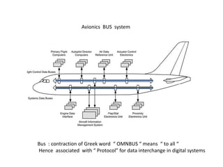
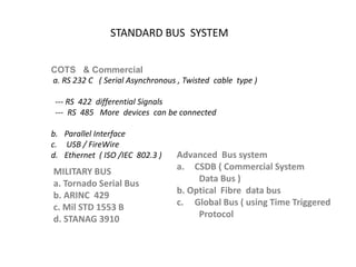
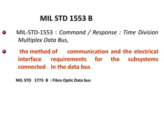
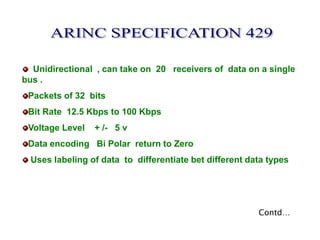
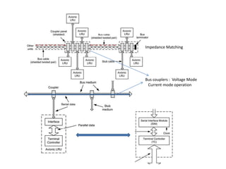
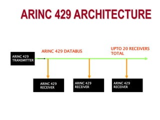
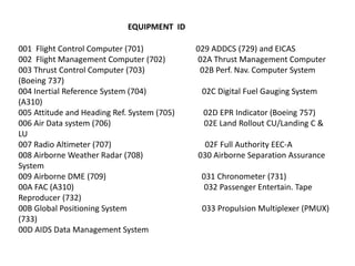
2. Avionics BUS system
Bus : contraction of Greek word “ OMNBUS “ means “ to all “
Hence associated with “ Protocol” for data interchange in digital systems
3. # It provides a medium for the exchange of
data and information between various
Avionics subsystems
# Integration of Avionics subsystems in
military or civil aircraft and spacecraft.
DATA BUS
4. set of formal rules and conventions governing
the flow of information among the systems
Low level protocols define the electrical and
physical standards
High level protocols deal with the data
formatting, including the syntax of messages
and its format
PROTOCOL
7. STANDARD BUS SYSTEM
COTS & Commercial
a. RS 232 C ( Serial Asynchronous , Twisted cable type )
--- RS 422 differential Signals
--- RS 485 More devices can be connected
b. Parallel Interface
c. USB / FireWire
d. Ethernet ( ISO /IEC 802.3 )
MILITARY BUS
a. Tornado Serial Bus
b. ARINC 429
c. Mil STD 1553 B
d. STANAG 3910
Advanced Bus system
a. CSDB ( Commercial System
Data Bus )
b. Optical Fibre data bus
c. Global Bus ( using Time Triggered
Protocol
9. Ethernet Protocol/Bus
Developed by XEROX PARC 1970. adopted as std in 1978.
Stds :
IEEE 802.3 : CSMA/CD Ethernet 2 Mbps
IEEE 802.3 U ; “ 100 Mbps
z : 1 Gbps
------------------------------------------------------------------------------
Topology
Shared access system : Bus , Ring ( token Ring ) , Star
Media Access control ( MAC ) Mechanism :
- CSMA / CD ( Broadcast Technology : when sensed collision stop sending )
{ each data frame separated by 9.6 μs – to switch from send to receive:}
-------------------------------------------------------------------------------------
Other IEEE Stds based on same concept :
IEEE 802 .11 WLAN
IEEE 802.15 Bluetooth
IEEE 802.16 Wi MAx
10. Ethernet Data Format
Preamble
64 bits
Source
add 48
Dest.Add
48
Type
Data
1500
CRC 32
Preamble : sequence of 7 bytes 10101010. : synchronization
Data : 1500 bytes
14. Developed at Wright Patterson Air Force
Base in 1970s
Published First Version 1553A in 1975
Introduced in service on F-15 Program
Published Second version 1553B in 1978
History : 1553 B
15. MIL-STD-1553 : Command / Response : Time Division
Multiplex Data Bus,
the method of communication and the electrical
interface requirements for the subsystems
connected in the data bus
MIL STD 1553 B
MIL STD 1773 B : Fibre Optic Data bus
16. Data Rate
Message Length
Data Bits per Word
Transmission Technique
Encoding
Protocol
1 Mbps
32 Word Strings(maximum)
16 Bits
Half - Duplex
Manchester II Bi-phase
Transmission Mode
Word Length 20 Bits
Voltage Mode
Command Response
21. ARINC : Aeronautical Radio Incorporated
Standards
ARINC 429 : Serial Data Bus standard
ARINC 615 : software Protocol ( high speed read / write )
ARINC 629 : 2 Mbps Bi directional standard
ARINC 708 : From Weather Radar to aircraft display data transfer std
ARINC 717 : Flight Data Recorder standard
ARINC : Aeronautical Radio Inc. funded by airlines, in charge of the
definition of Aeronautical standards that ensure interchange ability and
interoperability.
AEEC : Airlines Electronic Engineering Commitee
ADN : Aircraft Data Network working group
22. Unidirectional , can take on 20 receivers of data on a single
bus .
Packets of 32 bits
Bit Rate 12.5 Kbps to 100 Kbps
Voltage Level + /- 5 v
Data encoding Bi Polar return to Zero
Uses labeling of data to differentiate bet different data types
Contd…
23. ARINC 429 Data Packet
1-8
bits
Label
9-10
SDI
11-29
Data
30-31
SSM
32
Parity
Label : identifies what type of data e.g altitude . Airspeed etc
SDI : receivers are assigned ID code
SSM : specifies field such as North , south , + or –
P : Parity
26. 001 Flight Control Computer (701) 029 ADDCS (729) and EICAS
002 Flight Management Computer (702) 02A Thrust Management Computer
003 Thrust Control Computer (703) 02B Perf. Nav. Computer System
(Boeing 737)
004 Inertial Reference System (704) 02C Digital Fuel Gauging System
(A310)
005 Attitude and Heading Ref. System (705) 02D EPR Indicator (Boeing 757)
006 Air Data system (706) 02E Land Rollout CU/Landing C &
LU
007 Radio Altimeter (707) 02F Full Authority EEC-A
008 Airborne Weather Radar (708) 030 Airborne Separation Assurance
System
009 Airborne DME (709) 031 Chronometer (731)
00A FAC (A310) 032 Passenger Entertain. Tape
Reproducer (732)
00B Global Positioning System 033 Propulsion Multiplexer (PMUX)
(733)
00D AIDS Data Management System
EQUIPMENT ID
28. ARINC 429 is a differential line with bipolar non return to zero (BNRZ)
signaling. Differential voltage between two lines is +10V (between 7,25
and 11V), 10V (between -7.25 and -11V) or 0 V (between -0.5 and 0.5V)
for high, low and null respectively.
32 bit words are separated with 4 bit times of null gaps and each bit has a
transition from the zero volts according to BNRZ which together help in
synchronization without clock
Binary Data allocation : sign bit 1 ( Left , from , Below, South , West )
Sign bit 0 : ( North East , right, to , over)
31. 1977 => Boeing began to work on “DATAC”
project
1977 - 85 => DATAC Emerged as ARINC 629
1989 => ARINC 629 was adopted by AEEC
1990 => ARINC 629 was first implemented in BOEING-
777
32. ARINC 629 data :
Time Division Multiplex
Linear Bus
Multiple Transmitter Access
2 Mbps Data Rate
Current Mode Coupling
(Present implementation)
33. Data Rate
Message Length
Data Bits per Word
Transmission Technique
Encoding
Protocol
Transmission Mode
Word Length
2 Mbps
31 Word Strings(maximum)
16 Bits
Half - Duplex
Manchester II Bi-phase
Carrier Sense Multiple Access
Collision avoidance
Voltage Mode,Current Mode, Fiber Optic
Mode
20 Bits
Specifications