Downloaded 1,462 times

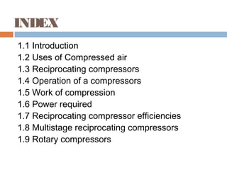
![Reciprocating compressor
efficiencies
(1) Mechanical efficiency
ῃ= I.P/B.P
(2) Isothermal efficiency
ῃiso = p1 V1 loge (p2/P1)
[ (n/n-1) p1V1 (p2/p1)n-1/n -1}]
(3) Volumetric efficiency
ῃ = 1- C [(p2/p1)1/n -1)]](https://image.slidesharecdn.com/eme-aircompressor-150514063233-lva1-app6892/85/Air-Compressor-12-320.jpg)
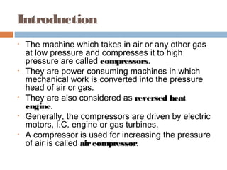
![Multistage reciprocating
compressor
There are several disadvantages to compress
the air at a high pressure in a single cylinder
the air is compressed by more than one
cylinder in series in a single stage compressor
if the pressure ratio is increased the volumetric
efficiency decrease .by the equation when the
pressure ratio is p2/p1=[1+1/c]n](https://image.slidesharecdn.com/eme-aircompressor-150514063233-lva1-app6892/85/Air-Compressor-13-320.jpg)
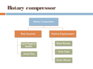
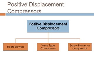
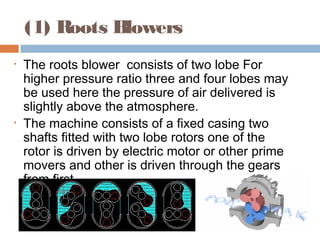
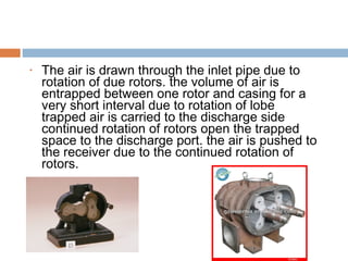
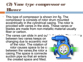

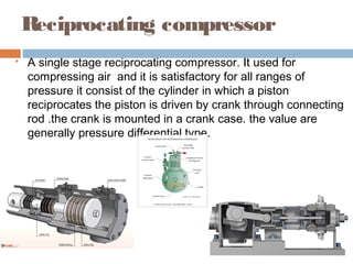
This document discusses different types of air compressors. It describes reciprocating compressors which use pistons driven by crankshafts to compress air in cylinders. It also describes rotary compressors like centrifugal compressors which use rapidly spinning impellers to accelerate and compress air, and axial compressors which use alternating rows of fixed and moving blades to compress air. The document also discusses positive displacement compressors like roots blowers which use interleaving lobes to trap and compress air, and vane compressors which use sliding vanes and an eccentric rotor to vary chamber volumes and compress air.


![SBP- Air compressor [Compatibility Mode].pdf](https://cdn.slidesharecdn.com/ss_thumbnails/sbp-aircompressorcompatibilitymode-241227102120-b6a67cde-thumbnail.jpg?width=640&height=640&fit=bounds)


