SlideShare a Scribd company logo
1 of 17
Download to read offline
1
Refrigeration effect (RE)
The amount of heat that is to be removed from the storage space in order to maintain lower temperatures is
called Refrigeration effect.
Significance of COP
COP represents running cost of the system, greater the COP lesser is the running cost. Therefore, systems with
higher COP are desired.
Note
COP can be greater than 1, equal to 1 or less than 1.
β†’ For Window air conditioning, COP ≃ 3.
β†’ For Domestic refrigeration, COP ≃ 1.
β†’ Vapour refrigeration system, COP <1.
Unit of Refrigeration (TR)
1 Ton of refrigeration (TR) means the amount of heat that is to be removed from 1 American ton (907 kg) of
water at 0⁰C in order to convert into ice at 0⁰C in 1 day.
Therefore, ton of refrigeration represents heat transfer rate not mass.
𝑇𝑅 =
π‘šΜ‡ Γ— 𝐿𝐻
1 π‘‘π‘Žπ‘¦
=
907 Γ— 334
24 Γ— 3600
= 3.5
π‘˜π½
𝑠𝑒𝑐⁄
1 𝑇𝑅 = 3.5
π‘˜π½
𝑠𝑒𝑐⁄
Refrigeration Capacity (RC)
𝑅𝐢 = π‘šΜ‡ Γ— 𝑅𝐸
RE is expressed in kJ/kg and RC is expressed in kJ/sec or kW.
Power input to compressor
𝑃𝑖𝑛 = π‘šΜ‡ Γ— 𝑀𝑖𝑛
π‘š β†’ π‘šπ‘Žπ‘ π‘  π‘“π‘™π‘œπ‘€ π‘Ÿπ‘Žπ‘‘π‘’ π‘œπ‘“ π‘Ÿπ‘’π‘“π‘Ÿπ‘–π‘”π‘’π‘Ÿπ‘Žπ‘›π‘‘ 𝑖𝑛 π‘ π‘¦π‘ π‘‘π‘’π‘š
𝐢𝑂𝑃 =
𝑅𝐢
π‘Šπ‘–π‘›
=
π‘šΜ‡ Γ— 𝑅𝐸
π‘šΜ‡ Γ— 𝑀𝑖𝑛
=
𝑅𝐸
𝑃𝑖𝑛
Energy Efficient ratio (EER)
While calculating COP, work input to compressor is taken into account.
𝐢𝑂𝑃 =
𝑅𝐸
𝑀𝑖𝑛
EER is the ratio if refrigeration effect to work input to motor.
𝐸𝐸𝑅 =
𝑅𝐸
𝑀𝑖𝑛(π‘šπ‘œπ‘‘π‘œπ‘Ÿ)
πΆπ‘œπ‘šπ‘π‘Ÿπ‘’π‘ π‘ π‘œπ‘Ÿ 𝑒𝑓𝑓𝑖𝑐𝑖𝑒𝑛𝑐𝑦 (πœ‚ π‘π‘œπ‘šπ‘) =
π‘ƒπ‘π‘œπ‘šπ‘
𝑃 π‘šπ‘œπ‘‘π‘œπ‘Ÿ
=
𝑀𝑖𝑛,π‘π‘œπ‘šπ‘π‘Ÿπ‘’π‘ π‘ π‘œπ‘Ÿ
𝑀𝑖𝑛,π‘šπ‘œπ‘‘π‘œπ‘Ÿ
2
Refrigeration cycles
Refrigeration is cooling of system below surroundings.
Melting of ice is the earliest method of refrigeration, here ice absorbs latent heat of fusion from surroundings.
Solid carbon dioxide (CO2) can also be used for refrigeration. Solid CO2 when exposed to atmosphere, it sublimates
(solid to vapor) by absorbing the latent heat of fusion.
Refrigeration by both ice and CO2 are non-cyclic processes.
Reversed Heat engine cycle
Heat is received from lower temperature and discharged to high temperature by receiving
inflow of work. The objective of a refrigerator is to maintain the refrigerated space at a low
temperature by removing heat from it. The objective of a heat pump, however, is to maintain a
heated space at a high temperature.
𝐢𝑂𝑃 =
π·π‘’π‘ π‘–π‘Ÿπ‘’π‘‘ 𝑒𝑓𝑓𝑒𝑐𝑑
π‘…π‘’π‘žπ‘’π‘–π‘Ÿπ‘’π‘‘ 𝑖𝑛𝑝𝑒𝑑
𝐢𝑂𝑃 π»π‘’π‘Žπ‘‘ π‘π‘’π‘šπ‘ =
𝑄1
π‘Š
=
𝑄1
𝑄1 βˆ’ 𝑄2
πΆπ‘‚π‘ƒπ‘…π‘’π‘“π‘Ÿπ‘–π‘”π‘’π‘Ÿπ‘Žπ‘‘π‘œπ‘Ÿ =
𝑄2
π‘Š
=
𝑄2
𝑄1 βˆ’ 𝑄2
𝐢𝑂𝑃 π»π‘’π‘Žπ‘‘ π‘π‘’π‘šπ‘ = πΆπ‘‚π‘ƒπ‘Ÿπ‘’π‘“π‘Ÿπ‘–π‘”π‘’π‘Ÿπ‘Žπ‘‘π‘œπ‘Ÿ + 1
Reversed Carnot cycle
Carnot cycle is a totally reversible cycle that consists of two reversible isothermal and two isentropic processes.
Reversing the cycle does also reverse the directions of any heat and work interactions. The result is a cycle that
operates in the counterclockwise direction on a T-s diagram, which is called the reversed Carnot cycle. A
refrigerator or heat pump that operates on the reversed Carnot cycle is called a Carnot refrigerator or a Carnot
heat pump.
𝐢𝑂𝑃 π»π‘’π‘Žπ‘‘ π‘π‘’π‘šπ‘ =
𝑄 𝐻
π‘Šπ‘π‘’π‘‘
=
𝑄 𝐻
𝑄 𝐻 βˆ’ 𝑄 𝐿
=
𝑇 𝐻
𝑇 𝐻 βˆ’ 𝑇𝐿
=
1
1 βˆ’
𝑇𝐿
𝑇 𝐻
⁄
πΆπ‘‚π‘ƒπ‘…π‘’π‘“π‘Ÿπ‘–π‘”π‘’π‘Ÿπ‘Žπ‘‘π‘œπ‘Ÿ =
𝑄 𝐿
π‘Šπ‘π‘’π‘‘
=
𝑄 𝐿
𝑄 𝐻 βˆ’ 𝑄 𝐿
=
𝑇𝐿
𝑇 𝐻 βˆ’ 𝑇𝐿
=
1
𝑇 𝐻
𝑇𝐿
⁄ βˆ’ 1
3
Vapour Compression refrigeration cycle
In an actual refrigeration cycle, turbine or expansion engine is not used as power output is very less and not cost
efficient. So, throttling valve is used for expansion. In Carnot cycle, the expansion and compression of liquid
vapour mixture in turbine and compressor are very difficult. So, these difficulties are eliminated by completely
evaporating the refrigerant in evaporator and by replacing the turbine with a throttling device.
1 β†’ 2 ⟹ π‘…π‘’π‘£π‘’π‘Ÿπ‘ π‘–π‘π‘™π‘’ π΄π‘‘π‘–π‘Žπ‘π‘Žπ‘‘π‘–π‘ π‘π‘œπ‘šπ‘π‘Ÿπ‘’π‘ π‘ π‘–π‘œπ‘›
2 β†’ 3 ⟹ πΆπ‘œπ‘›π‘ π‘‘π‘Žπ‘›π‘‘ π‘π‘Ÿπ‘’π‘ π‘ π‘’π‘Ÿπ‘’ β„Žπ‘’π‘Žπ‘‘ π‘Ÿπ‘’π‘—π‘’π‘π‘‘π‘–π‘œπ‘›
3 β†’ 4 ⟹ π‘‡β„Žπ‘Ÿπ‘œπ‘‘π‘‘π‘™π‘–π‘›π‘” (πΌπ‘ π‘’π‘›π‘‘β„Žπ‘Žπ‘™π‘β„Žπ‘–π‘ π‘π‘Ÿπ‘œπ‘π‘’π‘ π‘ )
4 β†’ 1 ⟹ πΆπ‘œπ‘›π‘ π‘‘π‘Žπ‘›π‘‘ π‘π‘Ÿπ‘’π‘ π‘ π‘’π‘Ÿπ‘’ β„Žπ‘’π‘Žπ‘‘ π‘Žπ‘‘π‘‘π‘–π‘‘π‘–π‘œπ‘›
β†’ Dry compression is preferred to wet compression
because the liquid refrigerant may damage the compressor.
β†’ In expansion valve, i.e., throttling, enthalpy remains
constant. Even though the process is adiabatic entropy is not
constant as process is irreversible and entropy increases in
irreversible process.
β†’ By throttling, the pressure of refrigerant drops at which
saturation temperature of refrigerant is below the
temperature of surroundings.
β†’ In evaporator, cooling effect is produced by absorbing
the heat at constant pressure from refrigerator space.
Analysis of cycle
1. π‘Šπ‘ = π‘Šπ‘π‘œπ‘šπ‘π‘Ÿπ‘’π‘ π‘ π‘œπ‘Ÿ = β„Ž2 βˆ’ β„Ž1
2. 𝑄 𝐻 = 𝑄 π‘Ÿπ‘’π‘—π‘’π‘π‘‘π‘’π‘‘ = β„Ž2 βˆ’ β„Ž3
3. β„Ž3 = β„Ž4
4. 𝑄 𝐿 = 𝑄 π‘Žπ‘‘π‘‘π‘’π‘‘ = β„Ž1 βˆ’ β„Ž4 = β„Ž1 βˆ’ β„Ž3
Refrigeration effect is the amount of heat absorbed in evaporator.
𝐢𝑂𝑃 =
𝑄 𝐿
π‘Šπ‘
=
β„Ž1 βˆ’ β„Ž3
β„Ž2 βˆ’ β„Ž1
4
Compressors are of 3 types. They are reciprocating, rotating and centrifugal.
When the volume flow rate is high, Centrifugal compressors are used. For small capacity rotary compressors are
used. Reciprocating compressors are used in plants up to 100 tonnes capacity, more than that centrifugal
compressors are used.
Volumetric efficiency of reciprocating compressor
πΆπ‘™π‘’π‘Žπ‘Ÿπ‘’π‘›π‘π‘’ π‘Ÿπ‘Žπ‘‘π‘–π‘œ (𝐢) =
𝑉𝑐
𝑉𝑠
=
𝑉3
𝑉1 βˆ’ 𝑉3
πœ‚ π‘£π‘œπ‘™ =
π‘‰π‘Žπ‘π‘‘π‘’π‘Žπ‘™
𝑉𝑠𝑀𝑒𝑝𝑑
=
𝑉1 βˆ’ 𝑉4
𝑉1 βˆ’ 𝑉3
πœ‚ π‘£π‘œπ‘™ =
𝑉1 βˆ’ 𝑉3 + 𝑉3 βˆ’ 𝑉4
𝑉1 βˆ’ 𝑉3
= 1 βˆ’
𝑉4 βˆ’ 𝑉3
𝑉1 βˆ’ 𝑉3
πœ‚ π‘£π‘œπ‘™ = 1 +
𝑉3
𝑉1 βˆ’ 𝑉3
(
𝑉4
𝑉3
βˆ’ 1) = 1 + 𝐢 (
𝑉4
𝑉3
βˆ’ 1) = 1 + 𝐢
𝑉4
𝑉3
βˆ’ 𝐢
(
𝑉4
𝑉3
= (
𝑃2
𝑃1
)
1
𝑛 𝑒
) 𝑛 𝑒 β†’ 𝑖𝑛𝑑𝑒π‘₯ π‘œπ‘“ 𝑒π‘₯π‘π‘Žπ‘›π‘ π‘–π‘œπ‘›
πœ‚ π‘£π‘œπ‘™ = 1 βˆ’ 𝐢 + 𝐢 (
𝑃2
𝑃1
)
1
𝑛 𝑒
πœ‚ =
π‘‰π‘Žπ‘π‘‘π‘’π‘Žπ‘™
𝑉𝑠𝑀𝑒𝑝𝑑
=
π‘šΜ‡ Β· 𝑣1
πœ‹
4
𝐷2 Β· 𝐿 Β· 𝑁 Β· 𝐾 Β·
1
60
π‘Šβ„Žπ‘’π‘Ÿπ‘’, π’ŽΜ‡ = π‘šπ‘Žπ‘ π‘  π‘“π‘™π‘œπ‘€ π‘Ÿπ‘Žπ‘‘π‘’ π‘œπ‘“ π‘Ÿπ‘’π‘“π‘Ÿπ‘–π‘”π‘’π‘Ÿπ‘Žπ‘›π‘‘, 𝒗 𝟏 = 𝑠𝑝𝑒𝑐𝑖𝑓𝑖𝑐 π‘£π‘œπ‘™π‘’π‘šπ‘’ π‘Žπ‘‘ π‘π‘œπ‘šπ‘π‘Ÿπ‘’π‘ π‘ π‘œπ‘Ÿ 𝑖𝑛𝑙𝑒𝑑
𝑫 & 𝑳 β†’ π·π‘–π‘Žπ‘šπ‘’π‘‘π‘’π‘Ÿ & πΏπ‘’π‘›π‘”π‘‘β„Ž π‘œπ‘“ π‘π‘œπ‘Ÿπ‘’, 𝑡 β†’ 𝑅𝑃𝑀, 𝑲 β†’ π‘›π‘œ. π‘œπ‘“ π‘π‘¦π‘™π‘–π‘›π‘‘π‘’π‘Ÿπ‘ 
Use of Flash chamber in Vapour compression cycle
The state of refrigerant when entering evaporator is in wet region. It is the liquid refrigerant that absorbs heat
from storage space. Therefore, flash chamber is used before evaporator, it separates liquid from vapour
refrigerant and allows only liquid refrigerant to pass through evaporator decreasing the size of evaporator.
There is no change in COP, RE and Winput when flash chamber is used.
5
Actual Vapour compression cycle
An actual vapor-compression refrigeration cycle differs from the ideal one mostly to the irreversibilities that
occur in various components. Two common sources of irreversibilities are fluid friction (causes pressure drops)
and heat transfer to or from the surroundings.
β†’ The refrigerant is slightly superheated at the
compressor inlet. This ensures that the refrigerant is
completely vaporized when it enters the compressor.
β†’ In compressor the pressure drop caused by fluid friction
and heat transfer from the surroundings to the
refrigerant can be very significant. Superheating the
refrigerant in turn increases the specific volume of
refrigerant increasing the power input.
β†’ Entropy of refrigerant can increase or decrease in
compression process depending upon if frictional loss or
heat loss dominates.
β†’ Entropy loss is desirable as less work input is enough
which can be done by cooling.
β†’ It is undesirable to route the refrigerant to the throttling
valve before the refrigerant is completely condensed.
Therefore, the refrigerant is subcooled before it enters
the throttling valve.
β†’ Throttling valve and the evaporator are usually located
very close to each other, so the pressure drops in the
connecting line is small.
Cascade Refrigeration System
For large industrial applications efficiency, not simplicity, is the major concern. Some industrial applications
require moderately low temperatures, and the temperature range they involve may be too large for a single vapor
compression refrigeration cycle to be practical. Solution is performing refrigeration in stages. Such refrigeration
cycles are called Cascade refrigeration cycles.
The two cycles are connected through the heat exchanger in the middle. The heat transfer from the fluid in the
bottom cycle should be equal to the heat transfer to the fluid in the top cycle.
6
Use of Heat exchangers in VC cycle
The primary purpose of using heat exchanger is to sub-cool the refrigerant which results in the increase of
refrigerant and refrigerant gets superheated results in dry compression.
𝐢𝑂𝑃 =
β„Ž6 βˆ’ β„Ž5
β„Ž2 βˆ’ β„Ž1
Applying steady flow equation, heat lost is equal to heat gain.
β„Ž1 βˆ’ β„Ž6 = β„Ž3 βˆ’ β„Ž4
𝑐 π‘£π‘Žπ‘π‘œπ‘’π‘Ÿ(𝑇1 βˆ’ 𝑇6) = π‘π‘™π‘–π‘žπ‘’π‘–π‘‘(𝑇3 βˆ’ 𝑇4)
Vapour Absorption Refrigeration system
7
Vapour absorption refrigeration system is used where there is a
source of inexpensive thermal energy at a temperature.
The most widely used absorption refrigeration system is the
ammonia–water system, where ammonia (NH3) serves as the
refrigerant and water (H2O) as the transport medium.
System looks very much like the vapor-compression system, except
that the compressor has been replaced by a complex absorption
mechanism consisting of an absorber, a pump, a generator, a
regenerator, a valve, and a rectifier.
Compared with vapor-compression systems, a liquid is compressed
instead of a vapor and thus the work input is very small.
The absorption refrigeration systems are much more expensive than
the vapor-compression refrigeration systems. They are more
complex and occupy more space, they are much less efficient.
πΆπ‘‚π‘ƒπ‘šπ‘Žπ‘₯ = (
𝑇𝐺 βˆ’ π‘‡π‘œ
𝑇𝐺
) Β· (
𝑇𝑅
π‘‡π‘œ βˆ’ 𝑇𝑅
)
πΆπ‘‚π‘ƒπ‘šπ‘Žπ‘₯ = πœ‚ π‘π‘Žπ‘Ÿπ‘›π‘œπ‘‘ Γ— πΆπ‘‚π‘ƒπ‘π‘Žπ‘Ÿπ‘›π‘œπ‘‘
Gas Refrigeration system
Gas refrigeration cycle operates on reverse Brayton cycles or reverse Joule cycle or Bell-Coleman cycle.
In gas refrigeration cycles, air is used as a refrigerant and the system is used in air-craft refrigeration system.
Though the COP of gas refrigeration system is low, it is still used in air-craft refrigeration systems because of its
low weight per ton of refrigeration.
The COP of gas refrigeration is lower because the refrigerant doesn’t undergo phase change, unlike vapour
compression refrigeration system it absorbs sensible heat whereas vapour refrigeration system absorbs latent
heat.
1 β†’ 2 ⟾ π‘…π‘’π‘£π‘’π‘Ÿπ‘ π‘–π‘π‘™π‘’ π‘Žπ‘‘π‘–π‘Žπ‘π‘‘π‘–π‘ π‘π‘œπ‘šπ‘π‘Ÿπ‘’π‘ π‘ π‘–π‘œπ‘›
2 β†’ 3 ⟾ πΆπ‘œπ‘›π‘ π‘‘π‘Žπ‘›π‘‘ π‘π‘Ÿπ‘’π‘ π‘ π‘’π‘Ÿπ‘’ β„Žπ‘’π‘Žπ‘‘ π‘Ÿπ‘’π‘—π‘’π‘π‘‘π‘–π‘œπ‘›
3 β†’ 4 ⟾ π‘…π‘’π‘£π‘’π‘Ÿπ‘ π‘–π‘π‘™π‘’ π‘Žπ‘‘π‘–π‘Žπ‘π‘‘π‘–π‘ 𝑒π‘₯π‘π‘Žπ‘›π‘ π‘–π‘œπ‘›
4 β†’ 1 ⟾ πΆπ‘œπ‘›π‘ π‘‘π‘Žπ‘›π‘‘ π‘π‘Ÿπ‘’π‘ π‘ π‘’π‘Ÿπ‘’ β„Žπ‘’π‘Žπ‘‘ π‘Žπ‘‘π‘‘π‘–π‘‘π‘–π‘œπ‘›
Analysis of the cycle
Assumptions
1. Each device can be treated as steady flow device.
2. Kinetic and potential changes are neglected.
3. The working fluid is treated as ideal gas.
4. Compression and expansion are assumed to be reversible
adiabatic.
5. Specific heats (cp and cv) are constant.
8
β†’ π‘Šπ‘π‘œπ‘šπ‘π‘Ÿπ‘’π‘ π‘ π‘œπ‘Ÿ = β„Ž2 βˆ’ β„Ž1 = 𝑐 𝑝(𝑇2 βˆ’ 𝑇1)
β†’ 𝑄 π‘Ÿπ‘’π‘—π‘’π‘π‘‘π‘’π‘‘ = β„Ž2 βˆ’ β„Ž3 = 𝑐 𝑝(𝑇2 βˆ’ 𝑇3)
β†’ π‘Šπ‘‘π‘’π‘Ÿπ‘π‘–π‘›π‘’ = β„Ž3 βˆ’ β„Ž4 = 𝑐 𝑝(𝑇3 βˆ’ 𝑇4)
β†’ 𝑄 π‘Žπ‘π‘ π‘œπ‘Ÿπ‘π‘’π‘‘ = 𝑅. 𝐸 = β„Ž1 βˆ’ β„Ž4 = 𝑐 𝑝(𝑇1 βˆ’ 𝑇4)
β†’ 𝐢𝑂𝑃 =
𝑅. 𝐸
π‘Šπ‘π‘œπ‘šπ‘π‘Ÿπ‘’π‘ π‘ π‘œπ‘Ÿ βˆ’ π‘Šπ‘‘π‘’π‘Ÿπ‘π‘–π‘›π‘’
β†’ 𝐢𝑂𝑃 =
𝑐 𝑝(𝑇1 βˆ’ 𝑇4)
𝑐 𝑝(𝑇1 βˆ’ 𝑇2) βˆ’ 𝑐 𝑝(𝑇3 βˆ’ 𝑇4)
=
(𝑇1 βˆ’ 𝑇4)
(𝑇1 βˆ’ 𝑇2) βˆ’ (𝑇3 βˆ’ 𝑇4)
β†’ 𝐢𝑂𝑃 =
1
(
𝑇2 βˆ’ 𝑇3
𝑇1 βˆ’ 𝑇4
) βˆ’ 1
=
1
𝑇3
𝑇4
βˆ’ 1
=
1
π‘Ÿπ‘
π›Ύβˆ’1
𝛾
βˆ’ 1
{
𝑇3
𝑇4
= (
𝑃3
𝑃4
)
π›Ύβˆ’1
𝛾
= (
𝑃2
𝑃1
)
π›Ύβˆ’1
𝛾
= π‘Ÿπ‘
π›Ύβˆ’1
𝛾
}
COP of gas refrigeration cycle depends on compression ratio or pressure ratio (rp).
With increase in pressure ratio, the work input increases and COP decreases.
If throttling is used in gas refrigeration cycle instead of isentropic expansion as the working fluid is an ideal gas
and during throttling enthalpy remains constant, temperature after throttling remains same and can’t absorb
heat from storage space.
Actual cycle
1 βˆ’ 2𝑠 βˆ’ 3 βˆ’ 4𝑠 ⟹ πΌπ‘‘π‘’π‘Žπ‘™ 𝑐𝑦𝑐𝑙𝑒
1 βˆ’ 2 βˆ’ 3 βˆ’ 4 ⟹ π΄π‘π‘‘π‘’π‘Žπ‘™ 𝑐𝑦𝑐𝑙𝑒
β†’ πœ‚ π‘π‘œπ‘šπ‘π‘Ÿπ‘’π‘ π‘ π‘œπ‘Ÿ =
β„Ž2𝑠 βˆ’ β„Ž1
β„Ž2 βˆ’ β„Ž1
=
𝑇2𝑠 βˆ’ 𝑇1
𝑇2 βˆ’ 𝑇1
β†’ πœ‚ π‘‘π‘’π‘Ÿπ‘π‘–π‘›π‘’ =
β„Ž3 βˆ’ β„Ž4
β„Ž3 βˆ’ β„Ž4𝑠
=
𝑇3 βˆ’ 𝑇4
𝑇3 βˆ’ 𝑇4𝑠
9
Refrigerants
Desirable properties of a refrigerants or selection of a refrigerant
The properties of refrigerant are broadly classified into
1. Thermodynamic
2. Chemical
3. Physical
Thermodynamic properties
Critical temperature
The critical temperature of a refrigerant must be high as possible. The critical temperature of CO2 and ethylene are
undesirable because their critical temperature is less than ambient summer temperature.
Refrigerant H2O NH3 R-12 R-22 R-134a CO2 Ethylene
Critical
temperature (⁰C)
374.1 132 111.5 96.5 101.2 31 10.6
Desirable Undesirable
Specific Heat
We know that 𝑐 = 𝑇 (
𝑑𝑆
𝑑𝑇
), as the liquid refrigerant undergoes throttling and for lesser irreversibilities dS must be small.
Therefore, specific heat of liquid refrigerant must be small.
As the vapour refrigerant is undergoing compression, the compression work must be small. For smaller compression work,
the degree of superheat (dT) must be small. Therefore, the specific heat of vapour refrigerant must be high.
Enthalpy of vaporization
Refrigerant with large enthalpy of vaporization (RE) is preferred because the larger the enthalpy of vaporization, lesser is
the mass flow rate for a given refrigeration capacity.
Refrigerant H2O NH3 R-22 R-12 R-134 a
Enthalpy of vaporization
(kJ/kg)
2261 1369 234.7 16.7 197.3
Larger the enthalpy of vaporization, lesser the mass flow rate.
Conductivity
Thermal conductivity of refrigerant must be high for better heat transfer.
Condenser & Evaporator pressure
Evaporator pressure must be close to atmospheric pressure as possible because if evaporator pressure is very low
atmosphere air can leak into system.
The condenser pressure must be moderate i.e., if the condenser pressure is high the compressor must do more work.
Pressure ratio
Low pressure ratios are desirable because higher the pressure ratio larger is the compressor work and less volumetric
efficiency.
Freezing point
The freezing point of refrigerant must be as low as possible, so that very low temperature can be achieved.
Freezing point of water is 0⁰C, which is very high. Hence, it can’t be used as refrigerant for producing low temperatures.
Specific volume of refrigerant at the inlet of compressor
The specific volume at the inlet of compressor should be small, because if the specific volume is large, the compressor size
will be large and hence reciprocating compressors are not used if specific volumes of refrigerant are large and, in that case,
centrifugal compressors are used. Ex- R-113.
COP
High COP’s are desired because larger is the COP smaller is the running cost. Though the latent heat of vaporization of NH3
is very large. It doesn’t help in anyway in the improvement of COP because the work input to the compressor is large
(because of high Ξ³) and hence COP of NH3 refrigeration system is almost same as other common refrigerants.
10
Compressor Discharge temperature
The compressor discharge temperature (T2) should not be very high. If the compressor discharge temperature is very high it
will damage the compressor. The compressor discharge of NH3 refrigeration system is very high (120⁰C) compared to other
common refrigerants. Therefore, NH3 compressors are generally water cooled/water jacketed.
For common refrigerants, the compressor discharge temperature is less than 75⁰C.
Boiling point
The boiling point if refrigerant must be low, if the Boiling point is low for a given evaporator pressure, low temperatures can
be achieved.
Chemical Properties
Flammability
Refrigerants must be inflammable.
Toxicity
Refrigerants must be non-toxic.
Ammonia is toxic and hence not used as refrigerant in domestic refrigerators, though it is cheap.
Action with oil
In compressors some oil is carried by high temperature refrigerant to condenser and finally to evaporator. In evaporator
refrigerant vaporizes and oil separates from refrigerant. This accumulation of oil in evaporator results in reduction of heat
transfer.
Refrigerants are immiscible with oil (ex- CO2, NH3) don’t present any problems because the oil is brought back to compressor
from evaporator.
Refrigerant that are partially miscible with oil (ex- R-22) create problems. So, synthetic oils are used instead of mineral oil.
Action with material of construction
Ammonia attacks copper and hence when ammonia is used as refrigerant, wrought iron or steel is used as material of
construction. Similarly CFC’s attack aluminium and hence CFC’s, copper is used as material of construction.
Physical Properties
Viscosity
For easy flow of refrigerant, viscosity should be low.
Leak detection
Refrigerant must not leak from the system and if at all it leaks it must be detectable.
Ammonia leaks are detectable by sulphur stick method. In presence of NH3, white fumes of ammonium sulphide are formed.
Freon leaks are detected by allied torch method. In presence of Freon’s colour of light changes from blue to bluish green.
Refrigerant Application
R-134a Domestic refrigerator
R-22 A/C
R-717 (NH3) Industrial application
Dry ice (Solid CO2) Transportation
Psychrometry
At temperatures below the critical temperature, the gas phase of a substance is frequently referred to as a
vapor. The term vapor implies a gaseous state that is close to the saturation region of the substance, raising the
possibility of condensation during a process.
Air in the atmosphere normally contains some water vapor (or moisture) and is referred to as atmospheric
air. By contrast, air that contains no water vapor is called dry air. Composition of dry air remains relatively
constant, but the amount of water vapor changes as a result of condensation and evaporation. Although the
amount of water vapor in the air is small, it plays a major role in human comfort. Therefore, it is an important
consideration in air-conditioning applications.
Dry air can be treated as an ideal gas with a constant cp value of 1.005 kJ/kgΒ·K.
11
β„Ž π‘‘π‘Ÿπ‘¦ π‘Žπ‘–π‘Ÿ = 𝑐 𝑝 Β· 𝑇 β„Ž π‘Ž = 𝑐 𝑝 Β· 𝑇 = 1.005
π‘˜π½
π‘˜π‘” Β· 𝐾
Β· 𝑻 𝐾 = 1.005 Β· 𝑻
π‘˜π½
π‘˜π‘”β„
π›₯β„Ž π‘‘π‘Ÿπ‘¦ π‘Žπ‘–π‘Ÿ = 𝑐 𝑝 Β· π›₯𝑇
Water vapor in air behaves as ideal gas and obeys the ideal-gas relation Pv = RT.
Then the atmospheric air can be treated as an ideal-gas mixture whose pressure is the sum of the partial
pressure of dry air Pa and that of water vapor Pv
𝑃 = π‘ƒπ‘Ž + 𝑃𝑣
The partial pressure of water vapor is usually referred to as the vapor pressure. It is the pressure water
vapor would exert if it existed alone at the temperature and volume of atmospheric air.
Since pv is very small, the saturation temperature of water vapor at that pressure is less than atmospheric
temperature. So, it exists in a superheated state.
The enthalpy of water vapor in air can be taken to be equal to the enthalpy of saturated vapor at the same
temperature.
Taking 0⁰C as the reference temperature, the enthalpy and enthalpy change of dry air can be determined.
The enthalpy of water vapor at 0⁰C is 2500.9 kJ/kg. The average cp value of water vapor in the temperature
range -10⁰C to 50⁰C can be taken to be 1.88 kJ/kg·⁰C.
β„Ž 𝑣 = β„Ž00 𝐢 + 𝑐 𝑝 Β· 𝑇 = 2500.9 + 1.88 Β· 𝑇
Specific Humidity (Ο‰)
It is the mass of water vapor present in a unit mass of dry air.
πœ” =
π‘š 𝑣
π‘š π‘Ž
=
π‘šπ‘Žπ‘ π‘  π‘œπ‘“ π‘€π‘Žπ‘‘π‘’π‘Ÿ π‘£π‘Žπ‘π‘œπ‘Ÿ π‘π‘Ÿπ‘’π‘ π‘’π‘›π‘‘ 𝑖𝑛 π‘Žπ‘–π‘Ÿ
π‘šπ‘Žπ‘ π‘  π‘œπ‘“ π‘‘π‘Ÿπ‘¦ π‘Žπ‘–π‘Ÿ
πœ” =
𝑃𝑣 Β· 𝑉
𝑅 𝑣 Β· 𝑇⁄
π‘ƒπ‘Ž Β· 𝑉
𝑅 π‘Ž Β· 𝑇⁄
=
𝑃𝑣
π‘ƒπ‘Ž
Γ—
𝑅 π‘Ž
𝑅 𝑣
=
𝑃𝑣
π‘ƒπ‘Ž
Γ—
𝑀 𝐻2 𝑂
𝑀 π‘Žπ‘–π‘Ÿ
=
𝑃𝑣
π‘ƒπ‘Ž
Γ—
18
29
= 0.622 Γ—
𝑃𝑣
π‘ƒπ‘Ž
πœ” = 0.622 Γ—
𝑃𝑣
π‘ƒπ‘Ž
= 0.622 Γ—
𝑃𝑣
𝑃 βˆ’ 𝑃𝑣
Dry air contains no water vapor, and thus its specific humidity is zero.
Relative Humidity (Ο•)
Amount of moisture the air holds (mv) relative to the maximum amount of moisture (mvs) the air can
hold at the same temperature is relative humidity.
πœ™ =
π‘š 𝑣
π‘š 𝑣𝑠
=
𝑃𝑣
𝑃𝑣𝑠
πœ™ =
π‘š 𝑣
π‘š 𝑣𝑠
=
𝑃𝑣 Β· 𝑉
𝑅 𝑣 Β· 𝑇⁄
𝑃𝑣𝑠 Β· 𝑉
𝑅 𝑣 Β· 𝑇⁄
=
𝑃𝑣
𝑃𝑣𝑠
⟹ πœ” = 0.622 Γ—
𝑃𝑣𝑠 Β· πœ™
𝑃 βˆ’ 𝑃𝑣𝑠 Β· πœ™
⟹ πœ™ =
πœ” Β· 𝑃
(0.622 + πœ”) Β· 𝑃𝑣𝑠
The relative humidity ranges from 0 for dry air to 1 for saturated air.
Relative humidity is generally expressed in percentage.
The amount of moisture air can hold depends on its temperature. Therefore, the relative humidity of air
changes with temperature even when its specific humidity remains constant.
12
The total enthalpy (an extensive property) of atmospheric air is the sum of the enthalpies of dry air and the water
vapor,
𝐻 = 𝐻 π‘Ž + 𝐻𝑣
𝐻 = π‘š π‘Ž Β· β„Ž π‘Ž + π‘š 𝑣 Β· β„Ž 𝑣
Dividing it by ma gives,
𝐻
π‘š π‘Ž
= β„Ž π‘Ž +
π‘š 𝑣
π‘š π‘Ž
Β· β„Ž 𝑣 ⟹ 𝒉 = 𝒉 𝒂 + 𝝎 Β· 𝒉 𝒗 β†’ β„Ž = β„Ž π‘Ž + πœ” Β· β„Ž 𝑣𝑠 (β„Ž 𝑣 = β„Ž 𝑣𝑠)
𝒉 β†’
π’†π’π’•π’‰π’‚π’π’‘π’‰π’š 𝒐𝒇 π’‚π’Šπ’“
π’Œπ’ˆ 𝒐𝒇 π’…π’“π’š π’‚π’Šπ’“
Ordinary temperature of atmospheric air is frequently referred to as the dry-bulb temperature.
Dew point temperature (Tdp)
The dew-point temperature Tdp is defined as the temperature at which condensation begins when
the air is cooled at constant pressure.
Tdp is the saturation temperature of water corresponding to the vapor
pressure.
As the air cools at constant pressure, the vapor pressure Pv remains
constant, the vapor in the air (state 1) undergoes a constant-pressure cooling
process until it strikes the saturated vapor line (state 2). The temperature at this
point is Tdp, if the temperature drops any further, some vapor condenses out. As a
result, the amount of vapor in the air decreases, which results in a decrease in Pv.
The air remains saturated during the condensation process and thus follows
a path of 100 % Relative humidity (the saturated vapor line). The ordinary
temperature and the dew-point temperature of saturated air are identical.
Adiabatic Saturation and wet-bulb temperature
One way of determining the relative humidity is to determine the dew-point
temperature of air. Knowing the dew-point temperature, we can determine the
vapor pressure Pv and thus the relative humidity. This approach is simple, but not
quite practical.
Another way of determining the absolute or relative humidity is related to
an adiabatic saturation process, shown schematically and on a T-s diagram.
Unsaturated air which has specific humidity Ο‰1 and T1 passes over liquid
water, as the air flows over the water, some water evaporates and mixes with the
airstream. Water vapor content increases and temperature decreases during the
process. If air flows long enough air becomes fully saturated at T2 and that
temperature is called Adiabatic saturation temperature.
If makeup water is supplied to the channel at the rate of evaporation at
temperature T2. The adiabatic saturation process described above can be
analyzed as a steady-flow process.
β†’ π‘šΜ‡ π‘Ž1
= π‘šΜ‡ π‘Ž2
= π‘šΜ‡ π‘Ž (π‘šπ‘Žπ‘ π‘  π‘“π‘™π‘œπ‘€ π‘Ÿπ‘Žπ‘‘π‘’ π‘œπ‘“ π‘‘π‘Ÿπ‘¦ π‘Žπ‘–π‘Ÿ π‘Ÿπ‘’π‘šπ‘Žπ‘–π‘›π‘  π‘π‘œπ‘›π‘ π‘‘π‘Žπ‘›π‘‘)
β†’ π‘šΜ‡ 𝑣1
+ π‘šΜ‡ 𝑓 = π‘šΜ‡ 𝑣2
(π‘šΜ‡ 𝑓 β†’ π‘Ÿπ‘Žπ‘‘π‘’ π‘œπ‘“ π‘’π‘£π‘Žπ‘π‘œπ‘Ÿπ‘Žπ‘‘π‘–π‘œπ‘›)
β†’ πœ”1 Β· π‘šΜ‡ π‘Ž + π‘šΜ‡ 𝑓 = πœ”2 Β· π‘šΜ‡ π‘Ž ⟹ π‘šΜ‡ 𝑓 = π‘šΜ‡ π‘Ž Γ— (πœ”2 βˆ’ πœ”1)
13
Energy balance,
𝐸𝑖𝑛 = 𝐸 π‘œπ‘’π‘‘
β†’ 𝐻1 + 𝐻𝑓 = 𝐻2
β†’ π‘šΜ‡ π‘Ž Β· β„Ž1 + π‘šΜ‡ 𝑓 Β· β„Žπ‘“2
= π‘šΜ‡ π‘Ž Β· β„Ž2 ⟹ π‘šΜ‡ π‘Ž Β· β„Ž1 + π‘šΜ‡ π‘Ž Γ— (πœ”2 βˆ’ πœ”1) Β· β„Ž 𝑓2
= π‘šΜ‡ π‘Ž Β· β„Ž2
𝐷𝑖𝑣𝑖𝑑𝑖𝑛𝑔 𝑏𝑦 π‘šΜ‡ ,
β†’ β„Ž1 + (πœ”2 βˆ’ πœ”1) Β· β„Ž 𝑓2
= β„Ž2
β†’ (𝑐 𝑝 Β· 𝑇1 + πœ”1 Β· β„Ž 𝑣1
) + (πœ”2 βˆ’ πœ”1) Β· β„Ž 𝑓2
= (𝑐 𝑝 Β· 𝑇2 + πœ”1 Β· β„Ž 𝑣2
)
πœ”1 =
𝑐 𝑝 Β· (𝑇2 βˆ’ 𝑇1) + πœ”2 Β· β„Ž 𝑣𝑓2
β„Ž 𝑣1
βˆ’ β„Žπ‘“2
β†’ πœ”2 =
πœ”1 Β· (β„Ž 𝑣1
βˆ’ β„Žπ‘“2
) βˆ’ 𝑐 𝑝 Β· (𝑇2 βˆ’ 𝑇1)
β„Ž 𝑣𝑓2
πœ”2 =
0.622 Β· 𝑃𝑣2
𝑃2 βˆ’ 𝑃𝑣2
(πœ™2 = 100%)
The adiabatic saturation process discussed above provides a means of determining the absolute or relative
humidity of air.
A more practical approach is to use a thermometer whose bulb is covered with a cotton wick saturated with
water and to blow air over the wick, as shown in. Temperature measured in this manner is called the wet-bulb
temperature Twb.
Degree of saturation (ΞΌ)
It’s the ratio of actual specific humidity to specific humidity under saturation conditions.
πœ‡ =
πœ”
πœ”π‘ 
πœ‡ =
πœ”
πœ”π‘ 
=
0.622 β‹… (
𝑃𝑣
𝑃𝑑 βˆ’ 𝑃𝑣
)
0.622 β‹… (
𝑃𝑣𝑠
𝑃𝑑 βˆ’ 𝑃𝑣𝑠
)
β†’ πœ‡ =
𝑃𝑣
𝑃𝑣𝑠
Γ—
𝑃𝑑 βˆ’ 𝑃𝑣𝑠
𝑃𝑑 βˆ’ 𝑃𝑣
πœ‡ = πœ™ β‹… (
𝑃𝑑 βˆ’ 𝑃𝑣𝑠
𝑃𝑑 βˆ’ 𝑃𝑣
)
14
Developing of Psychometric chart
𝑇 π‘–π‘›π‘π‘Ÿπ‘’π‘Žπ‘ π‘’π‘  β†’ 𝑃𝑣 π‘–π‘›π‘π‘Ÿπ‘’π‘Žπ‘ π‘’π‘  πœ” = 𝑓(𝑃𝑣)
We know that from T-S diagram, as Pv increases corresponding saturation temperature also increases, if these values are
plotted on Pv vs T diagram, we get the diagram.
We know that water vapour in air exists in super-heated state. Therefore, the region towards the right of saturation curve
shows superheated shows superheated region and hence this is the region of interest in psychrometry, we also now that Ο‰ is
a function of Pv, therefore, in psychrometry chart is replaced with Ο‰.
Psychrometric chart
Various lines on Psychrometric chart
15
Sensitive Heating or Cooling
Only the dry bulb temperature of air changes.
β†’ π‘šΜ‡ π‘Ž1
= π‘šΜ‡ π‘Ž2
= π‘šΜ‡ π‘Ž (π‘šπ‘Žπ‘ π‘  π‘“π‘™π‘œπ‘€ π‘Ÿπ‘Žπ‘‘π‘’ π‘œπ‘“ π‘‘π‘Ÿπ‘¦ π‘Žπ‘–π‘Ÿ π‘Ÿπ‘’π‘šπ‘Žπ‘–π‘›π‘  π‘π‘œπ‘›π‘ π‘‘π‘Žπ‘›π‘‘)
β†’ π‘š 𝑣1
= π‘š 𝑣2
= π‘šΜ‡ 𝑣 (π‘šπ‘Žπ‘ π‘  π‘“π‘™π‘œπ‘€ π‘Ÿπ‘Žπ‘‘π‘’ π‘œπ‘“ π‘šπ‘œπ‘–π‘ π‘‘π‘’π‘Ÿπ‘’ π‘Ÿπ‘’π‘šπ‘Žπ‘–π‘›π‘  π‘π‘œπ‘›π‘ π‘‘π‘Žπ‘›π‘‘)
β†’ πœ”1 Β· π‘š π‘Ž = πœ”2 Β· π‘š π‘Ž ⟹ πœ”1 = πœ”2 = πœ”
β†’ π‘šΜ‡ π‘Ž1
Β· β„Ž1 + 𝑄1βˆ’2 = π‘šΜ‡ π‘Ž2
Β· β„Ž2 (πΈπ‘›π‘’π‘Ÿπ‘”π‘¦ πΆπ‘œπ‘›π‘ π‘’π‘Ÿπ‘£π‘Žπ‘‘π‘–π‘œπ‘›)
β†’ 𝑄1βˆ’2 = π‘š π‘Ž Β· (β„Ž2 βˆ’ β„Ž1)
β†’ 𝑄1βˆ’2 = π‘š π‘Ž Β· [(𝑐 𝑝 Β· 𝑇2 + πœ” Β· (2500 + 𝑐 𝑝 𝑣
Β· 𝑇2)) βˆ’ (𝑐 𝑝 Β· 𝑇1 + πœ” Β· (2500 + 𝑐 𝑝 𝑣
Β· 𝑇1))]
β†’ 𝑄1βˆ’2 = π‘š π‘Ž Β· [(𝑐 𝑝 Β· (𝑇2 βˆ’ 𝑇1)) + πœ” (𝑐 𝑝 𝑣
Β· (𝑇2 βˆ’ 𝑇1))]
β†’ 𝑄1βˆ’2 = π‘š π‘Ž Β· [(1.005 Β· (𝑇2 βˆ’ 𝑇1)) + πœ”(1.88 Β· (𝑇2 βˆ’ 𝑇1))]
β†’ 𝑄1βˆ’2 = π‘š π‘Ž Β· (𝑇2 βˆ’ 𝑇1) Β· (1.005 + 1.88 Β· πœ”)
Cooling and Dehumidification
When the humidity ratio of air decreases, air is said to be dehumidified, when humidity increases, then air is
said to be humidified.
Cooling and dehumidification process is obtained when the air at
the given dry bulb temperature (DBT) and dew point (DPT)
temperature is cooled below the dew point temperature.
When the air comes in contact with the cooling coil that is
maintained at the temperature below its dew point temperature, its
DBT starts reducing and relative humidity (Ο•) starts increasing. The
process of cooling continues and at some point, it reaches the value of
dew point temperature of the air. At this point the water vapor within
the air starts getting converted into the dew particles due to which the
dew is formed on the surface of the cooling and the moisture content
of the air reduces thereby reducing its humidity level. Thus, when the
air is cooled below its dew point temperature, there is cooling as well
as dehumidification of air.
Air may be cooled and dehumidified by
a) Placing the evaporator coil across the air flow
b) Circulating chilled water in a tube placed across the air flow
c) By spraying chilled water to air in the form of fine mist to expose a large surface
16
β†’ π‘šΜ‡ π‘Ž1
= π‘šΜ‡ π‘Ž2
= π‘šΜ‡ π‘Ž
β†’ π‘šΜ‡ 𝑣1
= π‘šΜ‡ 𝑣2
+ π‘šΜ‡ 𝑓 ⟹ πœ”1 Β· π‘šΜ‡ π‘Ž = πœ”2 Β· π‘šΜ‡ π‘Ž + π‘šΜ‡ 𝑓
β†’ π‘šΜ‡ 𝑓 = π‘šΜ‡ π‘Ž Β· (πœ”1 βˆ’ πœ”2)
β†’ π‘šΜ‡ π‘Ž Β· β„Ž1 = π‘šΜ‡ π‘Ž Β· β„Ž2 + π‘šΜ‡ 𝑓 Β· β„Žπ‘“ + 𝑄1βˆ’2
β†’ 𝑄1βˆ’2 = π‘šΜ‡ π‘Ž Β· β„Ž1 βˆ’ π‘šΜ‡ π‘Ž Β· β„Ž2 βˆ’ π‘šΜ‡ 𝑓 Β· β„Žπ‘“
β†’ 𝑄1βˆ’2 = π‘šΜ‡ π‘Ž Β· [(β„Ž1 βˆ’ β„Ž2) βˆ’ (πœ”1 βˆ’ πœ”2) Β· β„Žπ‘“]
Here there is both sensible cooling and latent heat of vaporization.
β†’ β„Ž1 βˆ’ β„Ž2 = (β„Ž1 βˆ’ β„Ž π‘₯) + (β„Ž π‘₯ βˆ’ β„Ž2) = 𝑆𝑒𝑛𝑠𝑖𝑏𝑙𝑒 β„Žπ‘’π‘Žπ‘‘(𝑆𝐻) + πΏπ‘Žπ‘‘π‘’π‘›π‘‘ β„Žπ‘’π‘Žπ‘‘ (𝐿𝐻)
Heating and Humidification
Problems associated with the low relative humidity for winter air-
conditioning resulting from simple heating can be eliminated by
humidifying the heated air. This is accomplished by passing the air first
through a heating section (process 1-2) and then through a humidifying
section (process 2-3).
β†’ π‘šΜ‡ π‘Ž1
= π‘šΜ‡ π‘Ž2
= π‘šΜ‡ π‘Ž
β†’ π‘šΜ‡ 𝑣1
+ π‘šΜ‡ 𝑓 = π‘šΜ‡ 𝑣2
⟹ πœ”1 Β· π‘šΜ‡ π‘Ž + π‘šΜ‡ 𝑓 = πœ”2 Β· π‘šΜ‡ π‘Ž
β†’ π‘šΜ‡ 𝑓 = π‘šΜ‡ π‘Ž Β· (πœ”2 βˆ’ πœ”1)
β†’ π‘šΜ‡ π‘Ž Β· β„Ž1 + π‘šΜ‡ 𝑓 Β· β„Žπ‘“ + 𝑄1βˆ’2 = π‘šΜ‡ π‘Ž Β· β„Ž2
β†’ 𝑄1βˆ’2 = π‘šΜ‡ π‘Ž Β· [(β„Ž2 βˆ’ β„Ž1) βˆ’ (πœ”2 βˆ’ πœ”1) Β· β„Žπ‘“]
Chemical Dehumidification
Some substances like silica gel and activated alumina have great
affinity for water vapour. They are called adsorbents.
When air passes through a bed of silica gel, water vapour molecules
get adsorbed on its surface. Latent heat of condensation is released. So,
the temperature of air is increased.
17
Adiabatic evaporative cooling
When liquid water is circulated / sprayed through air (dry air +
water vapour), water is evaporated by absorbing heat from air thereby
increasing specific humidity and in process air is cooled as it gave
latent heat of evaporation to water. No heat transfer takes place
between the chamber and the surroundings. therefore, the energy
required for evaporation is suppled by the air and consequently DBT is
decreased. After the process has been in operation for a sufficient
length of time, circulating water approaches Wet bulb temperature
(WBT) of air.
β†’ π‘šΜ‡ π‘Ž1
= π‘šΜ‡ π‘Ž2
= π‘šΜ‡ π‘Ž
β†’ π‘šΜ‡ 𝑣1
+ π‘šΜ‡ 𝑓 = π‘šΜ‡ 𝑣2
β†’ π‘šΜ‡ 𝑓 = π‘šΜ‡ π‘Ž Γ— (πœ”2 βˆ’ πœ”1)
β†’ π‘šΜ‡ π‘Ž Β· β„Ž1 + π‘šΜ‡ 𝑓 Β· β„Ž 𝑓2
= π‘šΜ‡ π‘Ž Β· β„Ž2
β†’ β„Ž1 + (πœ”2 βˆ’ πœ”1) Β· β„Ž 𝑓2
= β„Ž2
Adiabatic mixing of 2 streams
β†’ π‘š π‘Ž1
+ π‘š π‘Ž2
= π‘š π‘Ž3
β†’ π‘š 𝑣1
+ π‘š 𝑣2
= π‘š 𝑣3
β†’ πœ”1 Β· π‘š π‘Ž1
+ πœ”2 Β· π‘š π‘Ž2
= πœ”3 Β· π‘š π‘Ž3
⟹ πœ”1 Β· π‘š π‘Ž1
+ πœ”2 Β· π‘š π‘Ž2
= (π‘š π‘Ž1
+ π‘š π‘Ž2
) Β· π‘š π‘Ž3
β†’ β„Ž1 Β· π‘š π‘Ž1
+ β„Ž2 Β· π‘š π‘Ž2
= π‘š π‘Ž3
Β· β„Ž3 ⟹ β„Ž1 Β· π‘š π‘Ž1
+ β„Ž2 Β· π‘š π‘Ž2
= (π‘š π‘Ž1
+ π‘š π‘Ž2
) Β· β„Ž3
π‘š π‘Ž1
π‘š π‘Ž2
=
β„Ž3 βˆ’ β„Ž2
β„Ž1 βˆ’ β„Ž3
=
πœ”3 βˆ’ πœ”2
πœ”1 βˆ’ πœ”3

More Related Content

What's hot

Formation and properties of steam
Formation and properties of steamFormation and properties of steam
Formation and properties of steamAnuharsh Gaur
Β 
PROPERTIES OF PURE SUBSTANCES
PROPERTIES OF PURE SUBSTANCESPROPERTIES OF PURE SUBSTANCES
PROPERTIES OF PURE SUBSTANCESnaphis ahamad
Β 
Vapour power cycles
Vapour power cyclesVapour power cycles
Vapour power cycleskrishna khot
Β 
Steam Formation
Steam FormationSteam Formation
Steam FormationMuveen Khan
Β 
Vapour power cycle a
Vapour power cycle aVapour power cycle a
Vapour power cycle anaphis ahamad
Β 
Chapter 3 Properties of Pure Substances
Chapter 3 Properties of Pure SubstancesChapter 3 Properties of Pure Substances
Chapter 3 Properties of Pure SubstancesANIKET SURYAWANSHI
Β 
Vapour compression refrigeration system
Vapour compression refrigeration systemVapour compression refrigeration system
Vapour compression refrigeration systemnaphis ahamad
Β 
reciprocating compressor
reciprocating compressorreciprocating compressor
reciprocating compressorRajesh Sharma
Β 
Vapour absorption system
Vapour absorption systemVapour absorption system
Vapour absorption systemnaphis ahamad
Β 
Air refrigeration systems
Air refrigeration systemsAir refrigeration systems
Air refrigeration systemsSuhail Bhatia
Β 
Refrigeration and Air Conditioning
Refrigeration and Air Conditioning Refrigeration and Air Conditioning
Refrigeration and Air Conditioning CHANDRA SEKHAR
Β 
Types of Rotary Compressors FPE
Types of Rotary Compressors FPETypes of Rotary Compressors FPE
Types of Rotary Compressors FPEAmit Mak
Β 
Critical thickness of insulation
Critical thickness of insulationCritical thickness of insulation
Critical thickness of insulationMdNoorruddin
Β 
Centrifugal Compressor
Centrifugal CompressorCentrifugal Compressor
Centrifugal CompressorAnkit Singh
Β 

What's hot (20)

Formation and properties of steam
Formation and properties of steamFormation and properties of steam
Formation and properties of steam
Β 
Refrigiration and air conditioning by abhishek singh
Refrigiration and air conditioning by abhishek singhRefrigiration and air conditioning by abhishek singh
Refrigiration and air conditioning by abhishek singh
Β 
vapour compression cycle
vapour compression cyclevapour compression cycle
vapour compression cycle
Β 
PROPERTIES OF PURE SUBSTANCES
PROPERTIES OF PURE SUBSTANCESPROPERTIES OF PURE SUBSTANCES
PROPERTIES OF PURE SUBSTANCES
Β 
Vapour power cycles
Vapour power cyclesVapour power cycles
Vapour power cycles
Β 
Steam Formation
Steam FormationSteam Formation
Steam Formation
Β 
Vapour power cycle a
Vapour power cycle aVapour power cycle a
Vapour power cycle a
Β 
Chapter 3 Properties of Pure Substances
Chapter 3 Properties of Pure SubstancesChapter 3 Properties of Pure Substances
Chapter 3 Properties of Pure Substances
Β 
Vapour compression refrigeration system
Vapour compression refrigeration systemVapour compression refrigeration system
Vapour compression refrigeration system
Β 
reciprocating compressor
reciprocating compressorreciprocating compressor
reciprocating compressor
Β 
DIESEL CYCLE
DIESEL CYCLEDIESEL CYCLE
DIESEL CYCLE
Β 
Vapour absorption system
Vapour absorption systemVapour absorption system
Vapour absorption system
Β 
Air refrigeration systems
Air refrigeration systemsAir refrigeration systems
Air refrigeration systems
Β 
Thermodynamic cycles
Thermodynamic cycles Thermodynamic cycles
Thermodynamic cycles
Β 
Refrigeration and Air Conditioning
Refrigeration and Air Conditioning Refrigeration and Air Conditioning
Refrigeration and Air Conditioning
Β 
nucleate boiling
nucleate boilingnucleate boiling
nucleate boiling
Β 
Types of Rotary Compressors FPE
Types of Rotary Compressors FPETypes of Rotary Compressors FPE
Types of Rotary Compressors FPE
Β 
Critical thickness of insulation
Critical thickness of insulationCritical thickness of insulation
Critical thickness of insulation
Β 
Centrifugal Compressor
Centrifugal CompressorCentrifugal Compressor
Centrifugal Compressor
Β 
Refrigeration
RefrigerationRefrigeration
Refrigeration
Β 

Similar to Refrigeration and air conditioning notes for gate

EME Refrigeration ppt.pptx
EME Refrigeration ppt.pptxEME Refrigeration ppt.pptx
EME Refrigeration ppt.pptxsameena232004
Β 
Chapter_11.ppt RAC REFRIGERATOR.ppt
Chapter_11.ppt RAC REFRIGERATOR.pptChapter_11.ppt RAC REFRIGERATOR.ppt
Chapter_11.ppt RAC REFRIGERATOR.pptGeoffreyMichael1
Β 
Refrigeration & Heat PUmps.pptx
Refrigeration & Heat PUmps.pptxRefrigeration & Heat PUmps.pptx
Refrigeration & Heat PUmps.pptxtraceyroberts30
Β 
Refrigeration and Air Conditioning
Refrigeration and Air ConditioningRefrigeration and Air Conditioning
Refrigeration and Air Conditioningdineshucer
Β 
Ch3- Refrigeration Systems-2.ppt
Ch3- Refrigeration Systems-2.pptCh3- Refrigeration Systems-2.ppt
Ch3- Refrigeration Systems-2.pptReemTaha14
Β 
Ch3- Refrigeration Systems-2.ppt
Ch3- Refrigeration Systems-2.pptCh3- Refrigeration Systems-2.ppt
Ch3- Refrigeration Systems-2.pptWasifRazzaq2
Β 
Ch3- Refrigeration Systems-2.ppt
Ch3- Refrigeration Systems-2.pptCh3- Refrigeration Systems-2.ppt
Ch3- Refrigeration Systems-2.pptRTOMPC
Β 
LU5 - Refrigeration.pptx
LU5 - Refrigeration.pptxLU5 - Refrigeration.pptx
LU5 - Refrigeration.pptxGeeDeville
Β 
Refrigeration and Heat Pump Systems
Refrigeration and Heat Pump SystemsRefrigeration and Heat Pump Systems
Refrigeration and Heat Pump SystemsSalman Jailani
Β 
Methods of Refrigeration.pdf
Methods of Refrigeration.pdfMethods of Refrigeration.pdf
Methods of Refrigeration.pdfzainulabideen762825
Β 
refrigeration in hvac
refrigeration in hvacrefrigeration in hvac
refrigeration in hvacsonam singh
Β 
Vapourcompressionrefrigeration 140614054320-phpapp02 (1)
Vapourcompressionrefrigeration 140614054320-phpapp02 (1)Vapourcompressionrefrigeration 140614054320-phpapp02 (1)
Vapourcompressionrefrigeration 140614054320-phpapp02 (1)Jagadeesan Jaga
Β 
Vapourcompressionrefrigeration 140614054320-phpapp02 (1)
Vapourcompressionrefrigeration 140614054320-phpapp02 (1)Vapourcompressionrefrigeration 140614054320-phpapp02 (1)
Vapourcompressionrefrigeration 140614054320-phpapp02 (1)Jagadeesan Jaga
Β 
Vapourcompressionrefrigeration 140614054320-phpapp02 (1)
Vapourcompressionrefrigeration 140614054320-phpapp02 (1)Vapourcompressionrefrigeration 140614054320-phpapp02 (1)
Vapourcompressionrefrigeration 140614054320-phpapp02 (1)Jagadeesan Jaga
Β 
WORKING OF HEAT PUMPS WITH (CO2) REFRIGERANT
WORKING OF HEAT PUMPS WITH (CO2) REFRIGERANT WORKING OF HEAT PUMPS WITH (CO2) REFRIGERANT
WORKING OF HEAT PUMPS WITH (CO2) REFRIGERANT Swathi Rampur
Β 
Refrigeration_PPT KM.ppt '
Refrigeration_PPT KM.ppt                            'Refrigeration_PPT KM.ppt                            '
Refrigeration_PPT KM.ppt 'Athar739197
Β 

Similar to Refrigeration and air conditioning notes for gate (20)

EME Refrigeration ppt.pptx
EME Refrigeration ppt.pptxEME Refrigeration ppt.pptx
EME Refrigeration ppt.pptx
Β 
Chapter_11.ppt RAC REFRIGERATOR.ppt
Chapter_11.ppt RAC REFRIGERATOR.pptChapter_11.ppt RAC REFRIGERATOR.ppt
Chapter_11.ppt RAC REFRIGERATOR.ppt
Β 
Refrigeration Senator Libya
Refrigeration  Senator LibyaRefrigeration  Senator Libya
Refrigeration Senator Libya
Β 
refrigeration.pptx
refrigeration.pptxrefrigeration.pptx
refrigeration.pptx
Β 
Refrigeration & Heat PUmps.pptx
Refrigeration & Heat PUmps.pptxRefrigeration & Heat PUmps.pptx
Refrigeration & Heat PUmps.pptx
Β 
Refrigeration and Air Conditioning
Refrigeration and Air ConditioningRefrigeration and Air Conditioning
Refrigeration and Air Conditioning
Β 
Ch3- Refrigeration Systems-2.ppt
Ch3- Refrigeration Systems-2.pptCh3- Refrigeration Systems-2.ppt
Ch3- Refrigeration Systems-2.ppt
Β 
Ch3- Refrigeration Systems-2.ppt
Ch3- Refrigeration Systems-2.pptCh3- Refrigeration Systems-2.ppt
Ch3- Refrigeration Systems-2.ppt
Β 
Ch3- Refrigeration Systems-2.ppt
Ch3- Refrigeration Systems-2.pptCh3- Refrigeration Systems-2.ppt
Ch3- Refrigeration Systems-2.ppt
Β 
LU5 - Refrigeration.pptx
LU5 - Refrigeration.pptxLU5 - Refrigeration.pptx
LU5 - Refrigeration.pptx
Β 
Refrigeration and Heat Pump Systems
Refrigeration and Heat Pump SystemsRefrigeration and Heat Pump Systems
Refrigeration and Heat Pump Systems
Β 
Methods of Refrigeration.pdf
Methods of Refrigeration.pdfMethods of Refrigeration.pdf
Methods of Refrigeration.pdf
Β 
CHAPTER 11.pdf
CHAPTER 11.pdfCHAPTER 11.pdf
CHAPTER 11.pdf
Β 
refrigeration in hvac
refrigeration in hvacrefrigeration in hvac
refrigeration in hvac
Β 
Refrigeration
RefrigerationRefrigeration
Refrigeration
Β 
Vapourcompressionrefrigeration 140614054320-phpapp02 (1)
Vapourcompressionrefrigeration 140614054320-phpapp02 (1)Vapourcompressionrefrigeration 140614054320-phpapp02 (1)
Vapourcompressionrefrigeration 140614054320-phpapp02 (1)
Β 
Vapourcompressionrefrigeration 140614054320-phpapp02 (1)
Vapourcompressionrefrigeration 140614054320-phpapp02 (1)Vapourcompressionrefrigeration 140614054320-phpapp02 (1)
Vapourcompressionrefrigeration 140614054320-phpapp02 (1)
Β 
Vapourcompressionrefrigeration 140614054320-phpapp02 (1)
Vapourcompressionrefrigeration 140614054320-phpapp02 (1)Vapourcompressionrefrigeration 140614054320-phpapp02 (1)
Vapourcompressionrefrigeration 140614054320-phpapp02 (1)
Β 
WORKING OF HEAT PUMPS WITH (CO2) REFRIGERANT
WORKING OF HEAT PUMPS WITH (CO2) REFRIGERANT WORKING OF HEAT PUMPS WITH (CO2) REFRIGERANT
WORKING OF HEAT PUMPS WITH (CO2) REFRIGERANT
Β 
Refrigeration_PPT KM.ppt '
Refrigeration_PPT KM.ppt                            'Refrigeration_PPT KM.ppt                            '
Refrigeration_PPT KM.ppt '
Β 

More from Soumith V

Theory of machines notes
Theory of machines notesTheory of machines notes
Theory of machines notesSoumith V
Β 
Heat transfer GATE notes
Heat transfer GATE notesHeat transfer GATE notes
Heat transfer GATE notesSoumith V
Β 
Research methodology
Research methodologyResearch methodology
Research methodologySoumith V
Β 
Stoicism and How to build Self Discipline
Stoicism and How to build Self DisciplineStoicism and How to build Self Discipline
Stoicism and How to build Self DisciplineSoumith V
Β 
Stoicism I
Stoicism   IStoicism   I
Stoicism ISoumith V
Β 
Actual cycles of IC engines
Actual cycles of IC enginesActual cycles of IC engines
Actual cycles of IC enginesSoumith V
Β 
Fuel air cycle
Fuel air cycleFuel air cycle
Fuel air cycleSoumith V
Β 
Air standard cycles
Air standard cyclesAir standard cycles
Air standard cyclesSoumith V
Β 
Guidelines for slide preparation
Guidelines for slide preparationGuidelines for slide preparation
Guidelines for slide preparationSoumith V
Β 
Applications of thermodynamics
Applications of thermodynamicsApplications of thermodynamics
Applications of thermodynamicsSoumith V
Β 
Study of heat transfer analysis in helical grooved pipe
Study of heat transfer analysis in helical grooved pipe Study of heat transfer analysis in helical grooved pipe
Study of heat transfer analysis in helical grooved pipe Soumith V
Β 
Power plant
Power plantPower plant
Power plantSoumith V
Β 
Alternative enery sources
Alternative enery sourcesAlternative enery sources
Alternative enery sourcesSoumith V
Β 
Radiation
RadiationRadiation
RadiationSoumith V
Β 
Fluid mechanics notes for gate
Fluid mechanics notes for gateFluid mechanics notes for gate
Fluid mechanics notes for gateSoumith V
Β 
thermodynamics notes for gate
thermodynamics notes for gatethermodynamics notes for gate
thermodynamics notes for gateSoumith V
Β 
Metrology
MetrologyMetrology
MetrologySoumith V
Β 
Industrial engineering notes for gate
Industrial engineering notes for gateIndustrial engineering notes for gate
Industrial engineering notes for gateSoumith V
Β 
kitting method
kitting methodkitting method
kitting methodSoumith V
Β 

More from Soumith V (19)

Theory of machines notes
Theory of machines notesTheory of machines notes
Theory of machines notes
Β 
Heat transfer GATE notes
Heat transfer GATE notesHeat transfer GATE notes
Heat transfer GATE notes
Β 
Research methodology
Research methodologyResearch methodology
Research methodology
Β 
Stoicism and How to build Self Discipline
Stoicism and How to build Self DisciplineStoicism and How to build Self Discipline
Stoicism and How to build Self Discipline
Β 
Stoicism I
Stoicism   IStoicism   I
Stoicism I
Β 
Actual cycles of IC engines
Actual cycles of IC enginesActual cycles of IC engines
Actual cycles of IC engines
Β 
Fuel air cycle
Fuel air cycleFuel air cycle
Fuel air cycle
Β 
Air standard cycles
Air standard cyclesAir standard cycles
Air standard cycles
Β 
Guidelines for slide preparation
Guidelines for slide preparationGuidelines for slide preparation
Guidelines for slide preparation
Β 
Applications of thermodynamics
Applications of thermodynamicsApplications of thermodynamics
Applications of thermodynamics
Β 
Study of heat transfer analysis in helical grooved pipe
Study of heat transfer analysis in helical grooved pipe Study of heat transfer analysis in helical grooved pipe
Study of heat transfer analysis in helical grooved pipe
Β 
Power plant
Power plantPower plant
Power plant
Β 
Alternative enery sources
Alternative enery sourcesAlternative enery sources
Alternative enery sources
Β 
Radiation
RadiationRadiation
Radiation
Β 
Fluid mechanics notes for gate
Fluid mechanics notes for gateFluid mechanics notes for gate
Fluid mechanics notes for gate
Β 
thermodynamics notes for gate
thermodynamics notes for gatethermodynamics notes for gate
thermodynamics notes for gate
Β 
Metrology
MetrologyMetrology
Metrology
Β 
Industrial engineering notes for gate
Industrial engineering notes for gateIndustrial engineering notes for gate
Industrial engineering notes for gate
Β 
kitting method
kitting methodkitting method
kitting method
Β 

Recently uploaded

What are the advantages and disadvantages of membrane structures.pptx
What are the advantages and disadvantages of membrane structures.pptxWhat are the advantages and disadvantages of membrane structures.pptx
What are the advantages and disadvantages of membrane structures.pptxwendy cai
Β 
HARMONY IN THE NATURE AND EXISTENCE - Unit-IV
HARMONY IN THE NATURE AND EXISTENCE - Unit-IVHARMONY IN THE NATURE AND EXISTENCE - Unit-IV
HARMONY IN THE NATURE AND EXISTENCE - Unit-IVRajaP95
Β 
CCS355 Neural Networks & Deep Learning Unit 1 PDF notes with Question bank .pdf
CCS355 Neural Networks & Deep Learning Unit 1 PDF notes with Question bank .pdfCCS355 Neural Networks & Deep Learning Unit 1 PDF notes with Question bank .pdf
CCS355 Neural Networks & Deep Learning Unit 1 PDF notes with Question bank .pdfAsst.prof M.Gokilavani
Β 
Architect Hassan Khalil Portfolio for 2024
Architect Hassan Khalil Portfolio for 2024Architect Hassan Khalil Portfolio for 2024
Architect Hassan Khalil Portfolio for 2024hassan khalil
Β 
Call Us ≽ 8377877756 β‰Ό Call Girls In Shastri Nagar (Delhi)
Call Us ≽ 8377877756 β‰Ό Call Girls In Shastri Nagar (Delhi)Call Us ≽ 8377877756 β‰Ό Call Girls In Shastri Nagar (Delhi)
Call Us ≽ 8377877756 β‰Ό Call Girls In Shastri Nagar (Delhi)dollysharma2066
Β 
Software and Systems Engineering Standards: Verification and Validation of Sy...
Software and Systems Engineering Standards: Verification and Validation of Sy...Software and Systems Engineering Standards: Verification and Validation of Sy...
Software and Systems Engineering Standards: Verification and Validation of Sy...VICTOR MAESTRE RAMIREZ
Β 
Concrete Mix Design - IS 10262-2019 - .pptx
Concrete Mix Design - IS 10262-2019 - .pptxConcrete Mix Design - IS 10262-2019 - .pptx
Concrete Mix Design - IS 10262-2019 - .pptxKartikeyaDwivedi3
Β 
IVE Industry Focused Event - Defence Sector 2024
IVE Industry Focused Event - Defence Sector 2024IVE Industry Focused Event - Defence Sector 2024
IVE Industry Focused Event - Defence Sector 2024Mark Billinghurst
Β 
Introduction-To-Agricultural-Surveillance-Rover.pptx
Introduction-To-Agricultural-Surveillance-Rover.pptxIntroduction-To-Agricultural-Surveillance-Rover.pptx
Introduction-To-Agricultural-Surveillance-Rover.pptxk795866
Β 
VICTOR MAESTRE RAMIREZ - Planetary Defender on NASA's Double Asteroid Redirec...
VICTOR MAESTRE RAMIREZ - Planetary Defender on NASA's Double Asteroid Redirec...VICTOR MAESTRE RAMIREZ - Planetary Defender on NASA's Double Asteroid Redirec...
VICTOR MAESTRE RAMIREZ - Planetary Defender on NASA's Double Asteroid Redirec...VICTOR MAESTRE RAMIREZ
Β 
Study on Air-Water & Water-Water Heat Exchange in a Finned ο»ΏTube Exchanger
Study on Air-Water & Water-Water Heat Exchange in a Finned ο»ΏTube ExchangerStudy on Air-Water & Water-Water Heat Exchange in a Finned ο»ΏTube Exchanger
Study on Air-Water & Water-Water Heat Exchange in a Finned ο»ΏTube ExchangerAnamika Sarkar
Β 
UNIT III ANALOG ELECTRONICS (BASIC ELECTRONICS)
UNIT III ANALOG ELECTRONICS (BASIC ELECTRONICS)UNIT III ANALOG ELECTRONICS (BASIC ELECTRONICS)
UNIT III ANALOG ELECTRONICS (BASIC ELECTRONICS)Dr SOUNDIRARAJ N
Β 
Churning of Butter, Factors affecting .
Churning of Butter, Factors affecting  .Churning of Butter, Factors affecting  .
Churning of Butter, Factors affecting .Satyam Kumar
Β 
DATA ANALYTICS PPT definition usage example
DATA ANALYTICS PPT definition usage exampleDATA ANALYTICS PPT definition usage example
DATA ANALYTICS PPT definition usage examplePragyanshuParadkar1
Β 
Arduino_CSE ece ppt for working and principal of arduino.ppt
Arduino_CSE ece ppt for working and principal of arduino.pptArduino_CSE ece ppt for working and principal of arduino.ppt
Arduino_CSE ece ppt for working and principal of arduino.pptSAURABHKUMAR892774
Β 
Call Girls Narol 7397865700 Independent Call Girls
Call Girls Narol 7397865700 Independent Call GirlsCall Girls Narol 7397865700 Independent Call Girls
Call Girls Narol 7397865700 Independent Call Girlsssuser7cb4ff
Β 
Call Girls Delhi {Jodhpur} 9711199012 high profile service
Call Girls Delhi {Jodhpur} 9711199012 high profile serviceCall Girls Delhi {Jodhpur} 9711199012 high profile service
Call Girls Delhi {Jodhpur} 9711199012 high profile servicerehmti665
Β 

Recently uploaded (20)

What are the advantages and disadvantages of membrane structures.pptx
What are the advantages and disadvantages of membrane structures.pptxWhat are the advantages and disadvantages of membrane structures.pptx
What are the advantages and disadvantages of membrane structures.pptx
Β 
Exploring_Network_Security_with_JA3_by_Rakesh Seal.pptx
Exploring_Network_Security_with_JA3_by_Rakesh Seal.pptxExploring_Network_Security_with_JA3_by_Rakesh Seal.pptx
Exploring_Network_Security_with_JA3_by_Rakesh Seal.pptx
Β 
HARMONY IN THE NATURE AND EXISTENCE - Unit-IV
HARMONY IN THE NATURE AND EXISTENCE - Unit-IVHARMONY IN THE NATURE AND EXISTENCE - Unit-IV
HARMONY IN THE NATURE AND EXISTENCE - Unit-IV
Β 
CCS355 Neural Networks & Deep Learning Unit 1 PDF notes with Question bank .pdf
CCS355 Neural Networks & Deep Learning Unit 1 PDF notes with Question bank .pdfCCS355 Neural Networks & Deep Learning Unit 1 PDF notes with Question bank .pdf
CCS355 Neural Networks & Deep Learning Unit 1 PDF notes with Question bank .pdf
Β 
Architect Hassan Khalil Portfolio for 2024
Architect Hassan Khalil Portfolio for 2024Architect Hassan Khalil Portfolio for 2024
Architect Hassan Khalil Portfolio for 2024
Β 
Call Us ≽ 8377877756 β‰Ό Call Girls In Shastri Nagar (Delhi)
Call Us ≽ 8377877756 β‰Ό Call Girls In Shastri Nagar (Delhi)Call Us ≽ 8377877756 β‰Ό Call Girls In Shastri Nagar (Delhi)
Call Us ≽ 8377877756 β‰Ό Call Girls In Shastri Nagar (Delhi)
Β 
young call girls in Rajiv ChowkπŸ” 9953056974 πŸ” Delhi escort Service
young call girls in Rajiv ChowkπŸ” 9953056974 πŸ” Delhi escort Serviceyoung call girls in Rajiv ChowkπŸ” 9953056974 πŸ” Delhi escort Service
young call girls in Rajiv ChowkπŸ” 9953056974 πŸ” Delhi escort Service
Β 
Software and Systems Engineering Standards: Verification and Validation of Sy...
Software and Systems Engineering Standards: Verification and Validation of Sy...Software and Systems Engineering Standards: Verification and Validation of Sy...
Software and Systems Engineering Standards: Verification and Validation of Sy...
Β 
Concrete Mix Design - IS 10262-2019 - .pptx
Concrete Mix Design - IS 10262-2019 - .pptxConcrete Mix Design - IS 10262-2019 - .pptx
Concrete Mix Design - IS 10262-2019 - .pptx
Β 
IVE Industry Focused Event - Defence Sector 2024
IVE Industry Focused Event - Defence Sector 2024IVE Industry Focused Event - Defence Sector 2024
IVE Industry Focused Event - Defence Sector 2024
Β 
Introduction-To-Agricultural-Surveillance-Rover.pptx
Introduction-To-Agricultural-Surveillance-Rover.pptxIntroduction-To-Agricultural-Surveillance-Rover.pptx
Introduction-To-Agricultural-Surveillance-Rover.pptx
Β 
VICTOR MAESTRE RAMIREZ - Planetary Defender on NASA's Double Asteroid Redirec...
VICTOR MAESTRE RAMIREZ - Planetary Defender on NASA's Double Asteroid Redirec...VICTOR MAESTRE RAMIREZ - Planetary Defender on NASA's Double Asteroid Redirec...
VICTOR MAESTRE RAMIREZ - Planetary Defender on NASA's Double Asteroid Redirec...
Β 
Study on Air-Water & Water-Water Heat Exchange in a Finned ο»ΏTube Exchanger
Study on Air-Water & Water-Water Heat Exchange in a Finned ο»ΏTube ExchangerStudy on Air-Water & Water-Water Heat Exchange in a Finned ο»ΏTube Exchanger
Study on Air-Water & Water-Water Heat Exchange in a Finned ο»ΏTube Exchanger
Β 
UNIT III ANALOG ELECTRONICS (BASIC ELECTRONICS)
UNIT III ANALOG ELECTRONICS (BASIC ELECTRONICS)UNIT III ANALOG ELECTRONICS (BASIC ELECTRONICS)
UNIT III ANALOG ELECTRONICS (BASIC ELECTRONICS)
Β 
Churning of Butter, Factors affecting .
Churning of Butter, Factors affecting  .Churning of Butter, Factors affecting  .
Churning of Butter, Factors affecting .
Β 
DATA ANALYTICS PPT definition usage example
DATA ANALYTICS PPT definition usage exampleDATA ANALYTICS PPT definition usage example
DATA ANALYTICS PPT definition usage example
Β 
Call Us -/9953056974- Call Girls In Vikaspuri-/- Delhi NCR
Call Us -/9953056974- Call Girls In Vikaspuri-/- Delhi NCRCall Us -/9953056974- Call Girls In Vikaspuri-/- Delhi NCR
Call Us -/9953056974- Call Girls In Vikaspuri-/- Delhi NCR
Β 
Arduino_CSE ece ppt for working and principal of arduino.ppt
Arduino_CSE ece ppt for working and principal of arduino.pptArduino_CSE ece ppt for working and principal of arduino.ppt
Arduino_CSE ece ppt for working and principal of arduino.ppt
Β 
Call Girls Narol 7397865700 Independent Call Girls
Call Girls Narol 7397865700 Independent Call GirlsCall Girls Narol 7397865700 Independent Call Girls
Call Girls Narol 7397865700 Independent Call Girls
Β 
Call Girls Delhi {Jodhpur} 9711199012 high profile service
Call Girls Delhi {Jodhpur} 9711199012 high profile serviceCall Girls Delhi {Jodhpur} 9711199012 high profile service
Call Girls Delhi {Jodhpur} 9711199012 high profile service
Β 

Refrigeration and air conditioning notes for gate

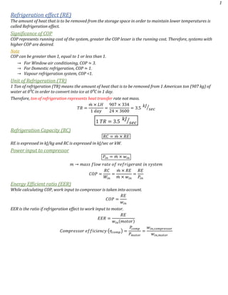
  • 1. 1 Refrigeration effect (RE) The amount of heat that is to be removed from the storage space in order to maintain lower temperatures is called Refrigeration effect. Significance of COP COP represents running cost of the system, greater the COP lesser is the running cost. Therefore, systems with higher COP are desired. Note COP can be greater than 1, equal to 1 or less than 1. β†’ For Window air conditioning, COP ≃ 3. β†’ For Domestic refrigeration, COP ≃ 1. β†’ Vapour refrigeration system, COP <1. Unit of Refrigeration (TR) 1 Ton of refrigeration (TR) means the amount of heat that is to be removed from 1 American ton (907 kg) of water at 0⁰C in order to convert into ice at 0⁰C in 1 day. Therefore, ton of refrigeration represents heat transfer rate not mass. 𝑇𝑅 = π‘šΜ‡ Γ— 𝐿𝐻 1 π‘‘π‘Žπ‘¦ = 907 Γ— 334 24 Γ— 3600 = 3.5 π‘˜π½ 𝑠𝑒𝑐⁄ 1 𝑇𝑅 = 3.5 π‘˜π½ 𝑠𝑒𝑐⁄ Refrigeration Capacity (RC) 𝑅𝐢 = π‘šΜ‡ Γ— 𝑅𝐸 RE is expressed in kJ/kg and RC is expressed in kJ/sec or kW. Power input to compressor 𝑃𝑖𝑛 = π‘šΜ‡ Γ— 𝑀𝑖𝑛 π‘š β†’ π‘šπ‘Žπ‘ π‘  π‘“π‘™π‘œπ‘€ π‘Ÿπ‘Žπ‘‘π‘’ π‘œπ‘“ π‘Ÿπ‘’π‘“π‘Ÿπ‘–π‘”π‘’π‘Ÿπ‘Žπ‘›π‘‘ 𝑖𝑛 π‘ π‘¦π‘ π‘‘π‘’π‘š 𝐢𝑂𝑃 = 𝑅𝐢 π‘Šπ‘–π‘› = π‘šΜ‡ Γ— 𝑅𝐸 π‘šΜ‡ Γ— 𝑀𝑖𝑛 = 𝑅𝐸 𝑃𝑖𝑛 Energy Efficient ratio (EER) While calculating COP, work input to compressor is taken into account. 𝐢𝑂𝑃 = 𝑅𝐸 𝑀𝑖𝑛 EER is the ratio if refrigeration effect to work input to motor. 𝐸𝐸𝑅 = 𝑅𝐸 𝑀𝑖𝑛(π‘šπ‘œπ‘‘π‘œπ‘Ÿ) πΆπ‘œπ‘šπ‘π‘Ÿπ‘’π‘ π‘ π‘œπ‘Ÿ 𝑒𝑓𝑓𝑖𝑐𝑖𝑒𝑛𝑐𝑦 (πœ‚ π‘π‘œπ‘šπ‘) = π‘ƒπ‘π‘œπ‘šπ‘ 𝑃 π‘šπ‘œπ‘‘π‘œπ‘Ÿ = 𝑀𝑖𝑛,π‘π‘œπ‘šπ‘π‘Ÿπ‘’π‘ π‘ π‘œπ‘Ÿ 𝑀𝑖𝑛,π‘šπ‘œπ‘‘π‘œπ‘Ÿ
  • 2. 2 Refrigeration cycles Refrigeration is cooling of system below surroundings. Melting of ice is the earliest method of refrigeration, here ice absorbs latent heat of fusion from surroundings. Solid carbon dioxide (CO2) can also be used for refrigeration. Solid CO2 when exposed to atmosphere, it sublimates (solid to vapor) by absorbing the latent heat of fusion. Refrigeration by both ice and CO2 are non-cyclic processes. Reversed Heat engine cycle Heat is received from lower temperature and discharged to high temperature by receiving inflow of work. The objective of a refrigerator is to maintain the refrigerated space at a low temperature by removing heat from it. The objective of a heat pump, however, is to maintain a heated space at a high temperature. 𝐢𝑂𝑃 = π·π‘’π‘ π‘–π‘Ÿπ‘’π‘‘ 𝑒𝑓𝑓𝑒𝑐𝑑 π‘…π‘’π‘žπ‘’π‘–π‘Ÿπ‘’π‘‘ 𝑖𝑛𝑝𝑒𝑑 𝐢𝑂𝑃 π»π‘’π‘Žπ‘‘ π‘π‘’π‘šπ‘ = 𝑄1 π‘Š = 𝑄1 𝑄1 βˆ’ 𝑄2 πΆπ‘‚π‘ƒπ‘…π‘’π‘“π‘Ÿπ‘–π‘”π‘’π‘Ÿπ‘Žπ‘‘π‘œπ‘Ÿ = 𝑄2 π‘Š = 𝑄2 𝑄1 βˆ’ 𝑄2 𝐢𝑂𝑃 π»π‘’π‘Žπ‘‘ π‘π‘’π‘šπ‘ = πΆπ‘‚π‘ƒπ‘Ÿπ‘’π‘“π‘Ÿπ‘–π‘”π‘’π‘Ÿπ‘Žπ‘‘π‘œπ‘Ÿ + 1 Reversed Carnot cycle Carnot cycle is a totally reversible cycle that consists of two reversible isothermal and two isentropic processes. Reversing the cycle does also reverse the directions of any heat and work interactions. The result is a cycle that operates in the counterclockwise direction on a T-s diagram, which is called the reversed Carnot cycle. A refrigerator or heat pump that operates on the reversed Carnot cycle is called a Carnot refrigerator or a Carnot heat pump. 𝐢𝑂𝑃 π»π‘’π‘Žπ‘‘ π‘π‘’π‘šπ‘ = 𝑄 𝐻 π‘Šπ‘π‘’π‘‘ = 𝑄 𝐻 𝑄 𝐻 βˆ’ 𝑄 𝐿 = 𝑇 𝐻 𝑇 𝐻 βˆ’ 𝑇𝐿 = 1 1 βˆ’ 𝑇𝐿 𝑇 𝐻 ⁄ πΆπ‘‚π‘ƒπ‘…π‘’π‘“π‘Ÿπ‘–π‘”π‘’π‘Ÿπ‘Žπ‘‘π‘œπ‘Ÿ = 𝑄 𝐿 π‘Šπ‘π‘’π‘‘ = 𝑄 𝐿 𝑄 𝐻 βˆ’ 𝑄 𝐿 = 𝑇𝐿 𝑇 𝐻 βˆ’ 𝑇𝐿 = 1 𝑇 𝐻 𝑇𝐿 ⁄ βˆ’ 1
  • 3. 3 Vapour Compression refrigeration cycle In an actual refrigeration cycle, turbine or expansion engine is not used as power output is very less and not cost efficient. So, throttling valve is used for expansion. In Carnot cycle, the expansion and compression of liquid vapour mixture in turbine and compressor are very difficult. So, these difficulties are eliminated by completely evaporating the refrigerant in evaporator and by replacing the turbine with a throttling device. 1 β†’ 2 ⟹ π‘…π‘’π‘£π‘’π‘Ÿπ‘ π‘–π‘π‘™π‘’ π΄π‘‘π‘–π‘Žπ‘π‘Žπ‘‘π‘–π‘ π‘π‘œπ‘šπ‘π‘Ÿπ‘’π‘ π‘ π‘–π‘œπ‘› 2 β†’ 3 ⟹ πΆπ‘œπ‘›π‘ π‘‘π‘Žπ‘›π‘‘ π‘π‘Ÿπ‘’π‘ π‘ π‘’π‘Ÿπ‘’ β„Žπ‘’π‘Žπ‘‘ π‘Ÿπ‘’π‘—π‘’π‘π‘‘π‘–π‘œπ‘› 3 β†’ 4 ⟹ π‘‡β„Žπ‘Ÿπ‘œπ‘‘π‘‘π‘™π‘–π‘›π‘” (πΌπ‘ π‘’π‘›π‘‘β„Žπ‘Žπ‘™π‘β„Žπ‘–π‘ π‘π‘Ÿπ‘œπ‘π‘’π‘ π‘ ) 4 β†’ 1 ⟹ πΆπ‘œπ‘›π‘ π‘‘π‘Žπ‘›π‘‘ π‘π‘Ÿπ‘’π‘ π‘ π‘’π‘Ÿπ‘’ β„Žπ‘’π‘Žπ‘‘ π‘Žπ‘‘π‘‘π‘–π‘‘π‘–π‘œπ‘› β†’ Dry compression is preferred to wet compression because the liquid refrigerant may damage the compressor. β†’ In expansion valve, i.e., throttling, enthalpy remains constant. Even though the process is adiabatic entropy is not constant as process is irreversible and entropy increases in irreversible process. β†’ By throttling, the pressure of refrigerant drops at which saturation temperature of refrigerant is below the temperature of surroundings. β†’ In evaporator, cooling effect is produced by absorbing the heat at constant pressure from refrigerator space. Analysis of cycle 1. π‘Šπ‘ = π‘Šπ‘π‘œπ‘šπ‘π‘Ÿπ‘’π‘ π‘ π‘œπ‘Ÿ = β„Ž2 βˆ’ β„Ž1 2. 𝑄 𝐻 = 𝑄 π‘Ÿπ‘’π‘—π‘’π‘π‘‘π‘’π‘‘ = β„Ž2 βˆ’ β„Ž3 3. β„Ž3 = β„Ž4 4. 𝑄 𝐿 = 𝑄 π‘Žπ‘‘π‘‘π‘’π‘‘ = β„Ž1 βˆ’ β„Ž4 = β„Ž1 βˆ’ β„Ž3 Refrigeration effect is the amount of heat absorbed in evaporator. 𝐢𝑂𝑃 = 𝑄 𝐿 π‘Šπ‘ = β„Ž1 βˆ’ β„Ž3 β„Ž2 βˆ’ β„Ž1
  • 4. 4 Compressors are of 3 types. They are reciprocating, rotating and centrifugal. When the volume flow rate is high, Centrifugal compressors are used. For small capacity rotary compressors are used. Reciprocating compressors are used in plants up to 100 tonnes capacity, more than that centrifugal compressors are used. Volumetric efficiency of reciprocating compressor πΆπ‘™π‘’π‘Žπ‘Ÿπ‘’π‘›π‘π‘’ π‘Ÿπ‘Žπ‘‘π‘–π‘œ (𝐢) = 𝑉𝑐 𝑉𝑠 = 𝑉3 𝑉1 βˆ’ 𝑉3 πœ‚ π‘£π‘œπ‘™ = π‘‰π‘Žπ‘π‘‘π‘’π‘Žπ‘™ 𝑉𝑠𝑀𝑒𝑝𝑑 = 𝑉1 βˆ’ 𝑉4 𝑉1 βˆ’ 𝑉3 πœ‚ π‘£π‘œπ‘™ = 𝑉1 βˆ’ 𝑉3 + 𝑉3 βˆ’ 𝑉4 𝑉1 βˆ’ 𝑉3 = 1 βˆ’ 𝑉4 βˆ’ 𝑉3 𝑉1 βˆ’ 𝑉3 πœ‚ π‘£π‘œπ‘™ = 1 + 𝑉3 𝑉1 βˆ’ 𝑉3 ( 𝑉4 𝑉3 βˆ’ 1) = 1 + 𝐢 ( 𝑉4 𝑉3 βˆ’ 1) = 1 + 𝐢 𝑉4 𝑉3 βˆ’ 𝐢 ( 𝑉4 𝑉3 = ( 𝑃2 𝑃1 ) 1 𝑛 𝑒 ) 𝑛 𝑒 β†’ 𝑖𝑛𝑑𝑒π‘₯ π‘œπ‘“ 𝑒π‘₯π‘π‘Žπ‘›π‘ π‘–π‘œπ‘› πœ‚ π‘£π‘œπ‘™ = 1 βˆ’ 𝐢 + 𝐢 ( 𝑃2 𝑃1 ) 1 𝑛 𝑒 πœ‚ = π‘‰π‘Žπ‘π‘‘π‘’π‘Žπ‘™ 𝑉𝑠𝑀𝑒𝑝𝑑 = π‘šΜ‡ Β· 𝑣1 πœ‹ 4 𝐷2 Β· 𝐿 Β· 𝑁 Β· 𝐾 Β· 1 60 π‘Šβ„Žπ‘’π‘Ÿπ‘’, π’ŽΜ‡ = π‘šπ‘Žπ‘ π‘  π‘“π‘™π‘œπ‘€ π‘Ÿπ‘Žπ‘‘π‘’ π‘œπ‘“ π‘Ÿπ‘’π‘“π‘Ÿπ‘–π‘”π‘’π‘Ÿπ‘Žπ‘›π‘‘, 𝒗 𝟏 = 𝑠𝑝𝑒𝑐𝑖𝑓𝑖𝑐 π‘£π‘œπ‘™π‘’π‘šπ‘’ π‘Žπ‘‘ π‘π‘œπ‘šπ‘π‘Ÿπ‘’π‘ π‘ π‘œπ‘Ÿ 𝑖𝑛𝑙𝑒𝑑 𝑫 & 𝑳 β†’ π·π‘–π‘Žπ‘šπ‘’π‘‘π‘’π‘Ÿ & πΏπ‘’π‘›π‘”π‘‘β„Ž π‘œπ‘“ π‘π‘œπ‘Ÿπ‘’, 𝑡 β†’ 𝑅𝑃𝑀, 𝑲 β†’ π‘›π‘œ. π‘œπ‘“ π‘π‘¦π‘™π‘–π‘›π‘‘π‘’π‘Ÿπ‘  Use of Flash chamber in Vapour compression cycle The state of refrigerant when entering evaporator is in wet region. It is the liquid refrigerant that absorbs heat from storage space. Therefore, flash chamber is used before evaporator, it separates liquid from vapour refrigerant and allows only liquid refrigerant to pass through evaporator decreasing the size of evaporator. There is no change in COP, RE and Winput when flash chamber is used.
  • 5. 5 Actual Vapour compression cycle An actual vapor-compression refrigeration cycle differs from the ideal one mostly to the irreversibilities that occur in various components. Two common sources of irreversibilities are fluid friction (causes pressure drops) and heat transfer to or from the surroundings. β†’ The refrigerant is slightly superheated at the compressor inlet. This ensures that the refrigerant is completely vaporized when it enters the compressor. β†’ In compressor the pressure drop caused by fluid friction and heat transfer from the surroundings to the refrigerant can be very significant. Superheating the refrigerant in turn increases the specific volume of refrigerant increasing the power input. β†’ Entropy of refrigerant can increase or decrease in compression process depending upon if frictional loss or heat loss dominates. β†’ Entropy loss is desirable as less work input is enough which can be done by cooling. β†’ It is undesirable to route the refrigerant to the throttling valve before the refrigerant is completely condensed. Therefore, the refrigerant is subcooled before it enters the throttling valve. β†’ Throttling valve and the evaporator are usually located very close to each other, so the pressure drops in the connecting line is small. Cascade Refrigeration System For large industrial applications efficiency, not simplicity, is the major concern. Some industrial applications require moderately low temperatures, and the temperature range they involve may be too large for a single vapor compression refrigeration cycle to be practical. Solution is performing refrigeration in stages. Such refrigeration cycles are called Cascade refrigeration cycles. The two cycles are connected through the heat exchanger in the middle. The heat transfer from the fluid in the bottom cycle should be equal to the heat transfer to the fluid in the top cycle.
  • 6. 6 Use of Heat exchangers in VC cycle The primary purpose of using heat exchanger is to sub-cool the refrigerant which results in the increase of refrigerant and refrigerant gets superheated results in dry compression. 𝐢𝑂𝑃 = β„Ž6 βˆ’ β„Ž5 β„Ž2 βˆ’ β„Ž1 Applying steady flow equation, heat lost is equal to heat gain. β„Ž1 βˆ’ β„Ž6 = β„Ž3 βˆ’ β„Ž4 𝑐 π‘£π‘Žπ‘π‘œπ‘’π‘Ÿ(𝑇1 βˆ’ 𝑇6) = π‘π‘™π‘–π‘žπ‘’π‘–π‘‘(𝑇3 βˆ’ 𝑇4) Vapour Absorption Refrigeration system
  • 7. 7 Vapour absorption refrigeration system is used where there is a source of inexpensive thermal energy at a temperature. The most widely used absorption refrigeration system is the ammonia–water system, where ammonia (NH3) serves as the refrigerant and water (H2O) as the transport medium. System looks very much like the vapor-compression system, except that the compressor has been replaced by a complex absorption mechanism consisting of an absorber, a pump, a generator, a regenerator, a valve, and a rectifier. Compared with vapor-compression systems, a liquid is compressed instead of a vapor and thus the work input is very small. The absorption refrigeration systems are much more expensive than the vapor-compression refrigeration systems. They are more complex and occupy more space, they are much less efficient. πΆπ‘‚π‘ƒπ‘šπ‘Žπ‘₯ = ( 𝑇𝐺 βˆ’ π‘‡π‘œ 𝑇𝐺 ) Β· ( 𝑇𝑅 π‘‡π‘œ βˆ’ 𝑇𝑅 ) πΆπ‘‚π‘ƒπ‘šπ‘Žπ‘₯ = πœ‚ π‘π‘Žπ‘Ÿπ‘›π‘œπ‘‘ Γ— πΆπ‘‚π‘ƒπ‘π‘Žπ‘Ÿπ‘›π‘œπ‘‘ Gas Refrigeration system Gas refrigeration cycle operates on reverse Brayton cycles or reverse Joule cycle or Bell-Coleman cycle. In gas refrigeration cycles, air is used as a refrigerant and the system is used in air-craft refrigeration system. Though the COP of gas refrigeration system is low, it is still used in air-craft refrigeration systems because of its low weight per ton of refrigeration. The COP of gas refrigeration is lower because the refrigerant doesn’t undergo phase change, unlike vapour compression refrigeration system it absorbs sensible heat whereas vapour refrigeration system absorbs latent heat. 1 β†’ 2 ⟾ π‘…π‘’π‘£π‘’π‘Ÿπ‘ π‘–π‘π‘™π‘’ π‘Žπ‘‘π‘–π‘Žπ‘π‘‘π‘–π‘ π‘π‘œπ‘šπ‘π‘Ÿπ‘’π‘ π‘ π‘–π‘œπ‘› 2 β†’ 3 ⟾ πΆπ‘œπ‘›π‘ π‘‘π‘Žπ‘›π‘‘ π‘π‘Ÿπ‘’π‘ π‘ π‘’π‘Ÿπ‘’ β„Žπ‘’π‘Žπ‘‘ π‘Ÿπ‘’π‘—π‘’π‘π‘‘π‘–π‘œπ‘› 3 β†’ 4 ⟾ π‘…π‘’π‘£π‘’π‘Ÿπ‘ π‘–π‘π‘™π‘’ π‘Žπ‘‘π‘–π‘Žπ‘π‘‘π‘–π‘ 𝑒π‘₯π‘π‘Žπ‘›π‘ π‘–π‘œπ‘› 4 β†’ 1 ⟾ πΆπ‘œπ‘›π‘ π‘‘π‘Žπ‘›π‘‘ π‘π‘Ÿπ‘’π‘ π‘ π‘’π‘Ÿπ‘’ β„Žπ‘’π‘Žπ‘‘ π‘Žπ‘‘π‘‘π‘–π‘‘π‘–π‘œπ‘› Analysis of the cycle Assumptions 1. Each device can be treated as steady flow device. 2. Kinetic and potential changes are neglected. 3. The working fluid is treated as ideal gas. 4. Compression and expansion are assumed to be reversible adiabatic. 5. Specific heats (cp and cv) are constant.
  • 8. 8 β†’ π‘Šπ‘π‘œπ‘šπ‘π‘Ÿπ‘’π‘ π‘ π‘œπ‘Ÿ = β„Ž2 βˆ’ β„Ž1 = 𝑐 𝑝(𝑇2 βˆ’ 𝑇1) β†’ 𝑄 π‘Ÿπ‘’π‘—π‘’π‘π‘‘π‘’π‘‘ = β„Ž2 βˆ’ β„Ž3 = 𝑐 𝑝(𝑇2 βˆ’ 𝑇3) β†’ π‘Šπ‘‘π‘’π‘Ÿπ‘π‘–π‘›π‘’ = β„Ž3 βˆ’ β„Ž4 = 𝑐 𝑝(𝑇3 βˆ’ 𝑇4) β†’ 𝑄 π‘Žπ‘π‘ π‘œπ‘Ÿπ‘π‘’π‘‘ = 𝑅. 𝐸 = β„Ž1 βˆ’ β„Ž4 = 𝑐 𝑝(𝑇1 βˆ’ 𝑇4) β†’ 𝐢𝑂𝑃 = 𝑅. 𝐸 π‘Šπ‘π‘œπ‘šπ‘π‘Ÿπ‘’π‘ π‘ π‘œπ‘Ÿ βˆ’ π‘Šπ‘‘π‘’π‘Ÿπ‘π‘–π‘›π‘’ β†’ 𝐢𝑂𝑃 = 𝑐 𝑝(𝑇1 βˆ’ 𝑇4) 𝑐 𝑝(𝑇1 βˆ’ 𝑇2) βˆ’ 𝑐 𝑝(𝑇3 βˆ’ 𝑇4) = (𝑇1 βˆ’ 𝑇4) (𝑇1 βˆ’ 𝑇2) βˆ’ (𝑇3 βˆ’ 𝑇4) β†’ 𝐢𝑂𝑃 = 1 ( 𝑇2 βˆ’ 𝑇3 𝑇1 βˆ’ 𝑇4 ) βˆ’ 1 = 1 𝑇3 𝑇4 βˆ’ 1 = 1 π‘Ÿπ‘ π›Ύβˆ’1 𝛾 βˆ’ 1 { 𝑇3 𝑇4 = ( 𝑃3 𝑃4 ) π›Ύβˆ’1 𝛾 = ( 𝑃2 𝑃1 ) π›Ύβˆ’1 𝛾 = π‘Ÿπ‘ π›Ύβˆ’1 𝛾 } COP of gas refrigeration cycle depends on compression ratio or pressure ratio (rp). With increase in pressure ratio, the work input increases and COP decreases. If throttling is used in gas refrigeration cycle instead of isentropic expansion as the working fluid is an ideal gas and during throttling enthalpy remains constant, temperature after throttling remains same and can’t absorb heat from storage space. Actual cycle 1 βˆ’ 2𝑠 βˆ’ 3 βˆ’ 4𝑠 ⟹ πΌπ‘‘π‘’π‘Žπ‘™ 𝑐𝑦𝑐𝑙𝑒 1 βˆ’ 2 βˆ’ 3 βˆ’ 4 ⟹ π΄π‘π‘‘π‘’π‘Žπ‘™ 𝑐𝑦𝑐𝑙𝑒 β†’ πœ‚ π‘π‘œπ‘šπ‘π‘Ÿπ‘’π‘ π‘ π‘œπ‘Ÿ = β„Ž2𝑠 βˆ’ β„Ž1 β„Ž2 βˆ’ β„Ž1 = 𝑇2𝑠 βˆ’ 𝑇1 𝑇2 βˆ’ 𝑇1 β†’ πœ‚ π‘‘π‘’π‘Ÿπ‘π‘–π‘›π‘’ = β„Ž3 βˆ’ β„Ž4 β„Ž3 βˆ’ β„Ž4𝑠 = 𝑇3 βˆ’ 𝑇4 𝑇3 βˆ’ 𝑇4𝑠
  • 9. 9 Refrigerants Desirable properties of a refrigerants or selection of a refrigerant The properties of refrigerant are broadly classified into 1. Thermodynamic 2. Chemical 3. Physical Thermodynamic properties Critical temperature The critical temperature of a refrigerant must be high as possible. The critical temperature of CO2 and ethylene are undesirable because their critical temperature is less than ambient summer temperature. Refrigerant H2O NH3 R-12 R-22 R-134a CO2 Ethylene Critical temperature (⁰C) 374.1 132 111.5 96.5 101.2 31 10.6 Desirable Undesirable Specific Heat We know that 𝑐 = 𝑇 ( 𝑑𝑆 𝑑𝑇 ), as the liquid refrigerant undergoes throttling and for lesser irreversibilities dS must be small. Therefore, specific heat of liquid refrigerant must be small. As the vapour refrigerant is undergoing compression, the compression work must be small. For smaller compression work, the degree of superheat (dT) must be small. Therefore, the specific heat of vapour refrigerant must be high. Enthalpy of vaporization Refrigerant with large enthalpy of vaporization (RE) is preferred because the larger the enthalpy of vaporization, lesser is the mass flow rate for a given refrigeration capacity. Refrigerant H2O NH3 R-22 R-12 R-134 a Enthalpy of vaporization (kJ/kg) 2261 1369 234.7 16.7 197.3 Larger the enthalpy of vaporization, lesser the mass flow rate. Conductivity Thermal conductivity of refrigerant must be high for better heat transfer. Condenser & Evaporator pressure Evaporator pressure must be close to atmospheric pressure as possible because if evaporator pressure is very low atmosphere air can leak into system. The condenser pressure must be moderate i.e., if the condenser pressure is high the compressor must do more work. Pressure ratio Low pressure ratios are desirable because higher the pressure ratio larger is the compressor work and less volumetric efficiency. Freezing point The freezing point of refrigerant must be as low as possible, so that very low temperature can be achieved. Freezing point of water is 0⁰C, which is very high. Hence, it can’t be used as refrigerant for producing low temperatures. Specific volume of refrigerant at the inlet of compressor The specific volume at the inlet of compressor should be small, because if the specific volume is large, the compressor size will be large and hence reciprocating compressors are not used if specific volumes of refrigerant are large and, in that case, centrifugal compressors are used. Ex- R-113. COP High COP’s are desired because larger is the COP smaller is the running cost. Though the latent heat of vaporization of NH3 is very large. It doesn’t help in anyway in the improvement of COP because the work input to the compressor is large (because of high Ξ³) and hence COP of NH3 refrigeration system is almost same as other common refrigerants.
  • 10. 10 Compressor Discharge temperature The compressor discharge temperature (T2) should not be very high. If the compressor discharge temperature is very high it will damage the compressor. The compressor discharge of NH3 refrigeration system is very high (120⁰C) compared to other common refrigerants. Therefore, NH3 compressors are generally water cooled/water jacketed. For common refrigerants, the compressor discharge temperature is less than 75⁰C. Boiling point The boiling point if refrigerant must be low, if the Boiling point is low for a given evaporator pressure, low temperatures can be achieved. Chemical Properties Flammability Refrigerants must be inflammable. Toxicity Refrigerants must be non-toxic. Ammonia is toxic and hence not used as refrigerant in domestic refrigerators, though it is cheap. Action with oil In compressors some oil is carried by high temperature refrigerant to condenser and finally to evaporator. In evaporator refrigerant vaporizes and oil separates from refrigerant. This accumulation of oil in evaporator results in reduction of heat transfer. Refrigerants are immiscible with oil (ex- CO2, NH3) don’t present any problems because the oil is brought back to compressor from evaporator. Refrigerant that are partially miscible with oil (ex- R-22) create problems. So, synthetic oils are used instead of mineral oil. Action with material of construction Ammonia attacks copper and hence when ammonia is used as refrigerant, wrought iron or steel is used as material of construction. Similarly CFC’s attack aluminium and hence CFC’s, copper is used as material of construction. Physical Properties Viscosity For easy flow of refrigerant, viscosity should be low. Leak detection Refrigerant must not leak from the system and if at all it leaks it must be detectable. Ammonia leaks are detectable by sulphur stick method. In presence of NH3, white fumes of ammonium sulphide are formed. Freon leaks are detected by allied torch method. In presence of Freon’s colour of light changes from blue to bluish green. Refrigerant Application R-134a Domestic refrigerator R-22 A/C R-717 (NH3) Industrial application Dry ice (Solid CO2) Transportation Psychrometry At temperatures below the critical temperature, the gas phase of a substance is frequently referred to as a vapor. The term vapor implies a gaseous state that is close to the saturation region of the substance, raising the possibility of condensation during a process. Air in the atmosphere normally contains some water vapor (or moisture) and is referred to as atmospheric air. By contrast, air that contains no water vapor is called dry air. Composition of dry air remains relatively constant, but the amount of water vapor changes as a result of condensation and evaporation. Although the amount of water vapor in the air is small, it plays a major role in human comfort. Therefore, it is an important consideration in air-conditioning applications. Dry air can be treated as an ideal gas with a constant cp value of 1.005 kJ/kgΒ·K.
  • 11. 11 β„Ž π‘‘π‘Ÿπ‘¦ π‘Žπ‘–π‘Ÿ = 𝑐 𝑝 Β· 𝑇 β„Ž π‘Ž = 𝑐 𝑝 Β· 𝑇 = 1.005 π‘˜π½ π‘˜π‘” Β· 𝐾 Β· 𝑻 𝐾 = 1.005 Β· 𝑻 π‘˜π½ π‘˜π‘”β„ π›₯β„Ž π‘‘π‘Ÿπ‘¦ π‘Žπ‘–π‘Ÿ = 𝑐 𝑝 Β· π›₯𝑇 Water vapor in air behaves as ideal gas and obeys the ideal-gas relation Pv = RT. Then the atmospheric air can be treated as an ideal-gas mixture whose pressure is the sum of the partial pressure of dry air Pa and that of water vapor Pv 𝑃 = π‘ƒπ‘Ž + 𝑃𝑣 The partial pressure of water vapor is usually referred to as the vapor pressure. It is the pressure water vapor would exert if it existed alone at the temperature and volume of atmospheric air. Since pv is very small, the saturation temperature of water vapor at that pressure is less than atmospheric temperature. So, it exists in a superheated state. The enthalpy of water vapor in air can be taken to be equal to the enthalpy of saturated vapor at the same temperature. Taking 0⁰C as the reference temperature, the enthalpy and enthalpy change of dry air can be determined. The enthalpy of water vapor at 0⁰C is 2500.9 kJ/kg. The average cp value of water vapor in the temperature range -10⁰C to 50⁰C can be taken to be 1.88 kJ/kg·⁰C. β„Ž 𝑣 = β„Ž00 𝐢 + 𝑐 𝑝 Β· 𝑇 = 2500.9 + 1.88 Β· 𝑇 Specific Humidity (Ο‰) It is the mass of water vapor present in a unit mass of dry air. πœ” = π‘š 𝑣 π‘š π‘Ž = π‘šπ‘Žπ‘ π‘  π‘œπ‘“ π‘€π‘Žπ‘‘π‘’π‘Ÿ π‘£π‘Žπ‘π‘œπ‘Ÿ π‘π‘Ÿπ‘’π‘ π‘’π‘›π‘‘ 𝑖𝑛 π‘Žπ‘–π‘Ÿ π‘šπ‘Žπ‘ π‘  π‘œπ‘“ π‘‘π‘Ÿπ‘¦ π‘Žπ‘–π‘Ÿ πœ” = 𝑃𝑣 Β· 𝑉 𝑅 𝑣 Β· 𝑇⁄ π‘ƒπ‘Ž Β· 𝑉 𝑅 π‘Ž Β· 𝑇⁄ = 𝑃𝑣 π‘ƒπ‘Ž Γ— 𝑅 π‘Ž 𝑅 𝑣 = 𝑃𝑣 π‘ƒπ‘Ž Γ— 𝑀 𝐻2 𝑂 𝑀 π‘Žπ‘–π‘Ÿ = 𝑃𝑣 π‘ƒπ‘Ž Γ— 18 29 = 0.622 Γ— 𝑃𝑣 π‘ƒπ‘Ž πœ” = 0.622 Γ— 𝑃𝑣 π‘ƒπ‘Ž = 0.622 Γ— 𝑃𝑣 𝑃 βˆ’ 𝑃𝑣 Dry air contains no water vapor, and thus its specific humidity is zero. Relative Humidity (Ο•) Amount of moisture the air holds (mv) relative to the maximum amount of moisture (mvs) the air can hold at the same temperature is relative humidity. πœ™ = π‘š 𝑣 π‘š 𝑣𝑠 = 𝑃𝑣 𝑃𝑣𝑠 πœ™ = π‘š 𝑣 π‘š 𝑣𝑠 = 𝑃𝑣 Β· 𝑉 𝑅 𝑣 Β· 𝑇⁄ 𝑃𝑣𝑠 Β· 𝑉 𝑅 𝑣 Β· 𝑇⁄ = 𝑃𝑣 𝑃𝑣𝑠 ⟹ πœ” = 0.622 Γ— 𝑃𝑣𝑠 Β· πœ™ 𝑃 βˆ’ 𝑃𝑣𝑠 Β· πœ™ ⟹ πœ™ = πœ” Β· 𝑃 (0.622 + πœ”) Β· 𝑃𝑣𝑠 The relative humidity ranges from 0 for dry air to 1 for saturated air. Relative humidity is generally expressed in percentage. The amount of moisture air can hold depends on its temperature. Therefore, the relative humidity of air changes with temperature even when its specific humidity remains constant.
  • 12. 12 The total enthalpy (an extensive property) of atmospheric air is the sum of the enthalpies of dry air and the water vapor, 𝐻 = 𝐻 π‘Ž + 𝐻𝑣 𝐻 = π‘š π‘Ž Β· β„Ž π‘Ž + π‘š 𝑣 Β· β„Ž 𝑣 Dividing it by ma gives, 𝐻 π‘š π‘Ž = β„Ž π‘Ž + π‘š 𝑣 π‘š π‘Ž Β· β„Ž 𝑣 ⟹ 𝒉 = 𝒉 𝒂 + 𝝎 Β· 𝒉 𝒗 β†’ β„Ž = β„Ž π‘Ž + πœ” Β· β„Ž 𝑣𝑠 (β„Ž 𝑣 = β„Ž 𝑣𝑠) 𝒉 β†’ π’†π’π’•π’‰π’‚π’π’‘π’‰π’š 𝒐𝒇 π’‚π’Šπ’“ π’Œπ’ˆ 𝒐𝒇 π’…π’“π’š π’‚π’Šπ’“ Ordinary temperature of atmospheric air is frequently referred to as the dry-bulb temperature. Dew point temperature (Tdp) The dew-point temperature Tdp is defined as the temperature at which condensation begins when the air is cooled at constant pressure. Tdp is the saturation temperature of water corresponding to the vapor pressure. As the air cools at constant pressure, the vapor pressure Pv remains constant, the vapor in the air (state 1) undergoes a constant-pressure cooling process until it strikes the saturated vapor line (state 2). The temperature at this point is Tdp, if the temperature drops any further, some vapor condenses out. As a result, the amount of vapor in the air decreases, which results in a decrease in Pv. The air remains saturated during the condensation process and thus follows a path of 100 % Relative humidity (the saturated vapor line). The ordinary temperature and the dew-point temperature of saturated air are identical. Adiabatic Saturation and wet-bulb temperature One way of determining the relative humidity is to determine the dew-point temperature of air. Knowing the dew-point temperature, we can determine the vapor pressure Pv and thus the relative humidity. This approach is simple, but not quite practical. Another way of determining the absolute or relative humidity is related to an adiabatic saturation process, shown schematically and on a T-s diagram. Unsaturated air which has specific humidity Ο‰1 and T1 passes over liquid water, as the air flows over the water, some water evaporates and mixes with the airstream. Water vapor content increases and temperature decreases during the process. If air flows long enough air becomes fully saturated at T2 and that temperature is called Adiabatic saturation temperature. If makeup water is supplied to the channel at the rate of evaporation at temperature T2. The adiabatic saturation process described above can be analyzed as a steady-flow process. β†’ π‘šΜ‡ π‘Ž1 = π‘šΜ‡ π‘Ž2 = π‘šΜ‡ π‘Ž (π‘šπ‘Žπ‘ π‘  π‘“π‘™π‘œπ‘€ π‘Ÿπ‘Žπ‘‘π‘’ π‘œπ‘“ π‘‘π‘Ÿπ‘¦ π‘Žπ‘–π‘Ÿ π‘Ÿπ‘’π‘šπ‘Žπ‘–π‘›π‘  π‘π‘œπ‘›π‘ π‘‘π‘Žπ‘›π‘‘) β†’ π‘šΜ‡ 𝑣1 + π‘šΜ‡ 𝑓 = π‘šΜ‡ 𝑣2 (π‘šΜ‡ 𝑓 β†’ π‘Ÿπ‘Žπ‘‘π‘’ π‘œπ‘“ π‘’π‘£π‘Žπ‘π‘œπ‘Ÿπ‘Žπ‘‘π‘–π‘œπ‘›) β†’ πœ”1 Β· π‘šΜ‡ π‘Ž + π‘šΜ‡ 𝑓 = πœ”2 Β· π‘šΜ‡ π‘Ž ⟹ π‘šΜ‡ 𝑓 = π‘šΜ‡ π‘Ž Γ— (πœ”2 βˆ’ πœ”1)
  • 13. 13 Energy balance, 𝐸𝑖𝑛 = 𝐸 π‘œπ‘’π‘‘ β†’ 𝐻1 + 𝐻𝑓 = 𝐻2 β†’ π‘šΜ‡ π‘Ž Β· β„Ž1 + π‘šΜ‡ 𝑓 Β· β„Žπ‘“2 = π‘šΜ‡ π‘Ž Β· β„Ž2 ⟹ π‘šΜ‡ π‘Ž Β· β„Ž1 + π‘šΜ‡ π‘Ž Γ— (πœ”2 βˆ’ πœ”1) Β· β„Ž 𝑓2 = π‘šΜ‡ π‘Ž Β· β„Ž2 𝐷𝑖𝑣𝑖𝑑𝑖𝑛𝑔 𝑏𝑦 π‘šΜ‡ , β†’ β„Ž1 + (πœ”2 βˆ’ πœ”1) Β· β„Ž 𝑓2 = β„Ž2 β†’ (𝑐 𝑝 Β· 𝑇1 + πœ”1 Β· β„Ž 𝑣1 ) + (πœ”2 βˆ’ πœ”1) Β· β„Ž 𝑓2 = (𝑐 𝑝 Β· 𝑇2 + πœ”1 Β· β„Ž 𝑣2 ) πœ”1 = 𝑐 𝑝 Β· (𝑇2 βˆ’ 𝑇1) + πœ”2 Β· β„Ž 𝑣𝑓2 β„Ž 𝑣1 βˆ’ β„Žπ‘“2 β†’ πœ”2 = πœ”1 Β· (β„Ž 𝑣1 βˆ’ β„Žπ‘“2 ) βˆ’ 𝑐 𝑝 Β· (𝑇2 βˆ’ 𝑇1) β„Ž 𝑣𝑓2 πœ”2 = 0.622 Β· 𝑃𝑣2 𝑃2 βˆ’ 𝑃𝑣2 (πœ™2 = 100%) The adiabatic saturation process discussed above provides a means of determining the absolute or relative humidity of air. A more practical approach is to use a thermometer whose bulb is covered with a cotton wick saturated with water and to blow air over the wick, as shown in. Temperature measured in this manner is called the wet-bulb temperature Twb. Degree of saturation (ΞΌ) It’s the ratio of actual specific humidity to specific humidity under saturation conditions. πœ‡ = πœ” πœ”π‘  πœ‡ = πœ” πœ”π‘  = 0.622 β‹… ( 𝑃𝑣 𝑃𝑑 βˆ’ 𝑃𝑣 ) 0.622 β‹… ( 𝑃𝑣𝑠 𝑃𝑑 βˆ’ 𝑃𝑣𝑠 ) β†’ πœ‡ = 𝑃𝑣 𝑃𝑣𝑠 Γ— 𝑃𝑑 βˆ’ 𝑃𝑣𝑠 𝑃𝑑 βˆ’ 𝑃𝑣 πœ‡ = πœ™ β‹… ( 𝑃𝑑 βˆ’ 𝑃𝑣𝑠 𝑃𝑑 βˆ’ 𝑃𝑣 )
  • 14. 14 Developing of Psychometric chart 𝑇 π‘–π‘›π‘π‘Ÿπ‘’π‘Žπ‘ π‘’π‘  β†’ 𝑃𝑣 π‘–π‘›π‘π‘Ÿπ‘’π‘Žπ‘ π‘’π‘  πœ” = 𝑓(𝑃𝑣) We know that from T-S diagram, as Pv increases corresponding saturation temperature also increases, if these values are plotted on Pv vs T diagram, we get the diagram. We know that water vapour in air exists in super-heated state. Therefore, the region towards the right of saturation curve shows superheated shows superheated region and hence this is the region of interest in psychrometry, we also now that Ο‰ is a function of Pv, therefore, in psychrometry chart is replaced with Ο‰. Psychrometric chart Various lines on Psychrometric chart
  • 15. 15 Sensitive Heating or Cooling Only the dry bulb temperature of air changes. β†’ π‘šΜ‡ π‘Ž1 = π‘šΜ‡ π‘Ž2 = π‘šΜ‡ π‘Ž (π‘šπ‘Žπ‘ π‘  π‘“π‘™π‘œπ‘€ π‘Ÿπ‘Žπ‘‘π‘’ π‘œπ‘“ π‘‘π‘Ÿπ‘¦ π‘Žπ‘–π‘Ÿ π‘Ÿπ‘’π‘šπ‘Žπ‘–π‘›π‘  π‘π‘œπ‘›π‘ π‘‘π‘Žπ‘›π‘‘) β†’ π‘š 𝑣1 = π‘š 𝑣2 = π‘šΜ‡ 𝑣 (π‘šπ‘Žπ‘ π‘  π‘“π‘™π‘œπ‘€ π‘Ÿπ‘Žπ‘‘π‘’ π‘œπ‘“ π‘šπ‘œπ‘–π‘ π‘‘π‘’π‘Ÿπ‘’ π‘Ÿπ‘’π‘šπ‘Žπ‘–π‘›π‘  π‘π‘œπ‘›π‘ π‘‘π‘Žπ‘›π‘‘) β†’ πœ”1 Β· π‘š π‘Ž = πœ”2 Β· π‘š π‘Ž ⟹ πœ”1 = πœ”2 = πœ” β†’ π‘šΜ‡ π‘Ž1 Β· β„Ž1 + 𝑄1βˆ’2 = π‘šΜ‡ π‘Ž2 Β· β„Ž2 (πΈπ‘›π‘’π‘Ÿπ‘”π‘¦ πΆπ‘œπ‘›π‘ π‘’π‘Ÿπ‘£π‘Žπ‘‘π‘–π‘œπ‘›) β†’ 𝑄1βˆ’2 = π‘š π‘Ž Β· (β„Ž2 βˆ’ β„Ž1) β†’ 𝑄1βˆ’2 = π‘š π‘Ž Β· [(𝑐 𝑝 Β· 𝑇2 + πœ” Β· (2500 + 𝑐 𝑝 𝑣 Β· 𝑇2)) βˆ’ (𝑐 𝑝 Β· 𝑇1 + πœ” Β· (2500 + 𝑐 𝑝 𝑣 Β· 𝑇1))] β†’ 𝑄1βˆ’2 = π‘š π‘Ž Β· [(𝑐 𝑝 Β· (𝑇2 βˆ’ 𝑇1)) + πœ” (𝑐 𝑝 𝑣 Β· (𝑇2 βˆ’ 𝑇1))] β†’ 𝑄1βˆ’2 = π‘š π‘Ž Β· [(1.005 Β· (𝑇2 βˆ’ 𝑇1)) + πœ”(1.88 Β· (𝑇2 βˆ’ 𝑇1))] β†’ 𝑄1βˆ’2 = π‘š π‘Ž Β· (𝑇2 βˆ’ 𝑇1) Β· (1.005 + 1.88 Β· πœ”) Cooling and Dehumidification When the humidity ratio of air decreases, air is said to be dehumidified, when humidity increases, then air is said to be humidified. Cooling and dehumidification process is obtained when the air at the given dry bulb temperature (DBT) and dew point (DPT) temperature is cooled below the dew point temperature. When the air comes in contact with the cooling coil that is maintained at the temperature below its dew point temperature, its DBT starts reducing and relative humidity (Ο•) starts increasing. The process of cooling continues and at some point, it reaches the value of dew point temperature of the air. At this point the water vapor within the air starts getting converted into the dew particles due to which the dew is formed on the surface of the cooling and the moisture content of the air reduces thereby reducing its humidity level. Thus, when the air is cooled below its dew point temperature, there is cooling as well as dehumidification of air. Air may be cooled and dehumidified by a) Placing the evaporator coil across the air flow b) Circulating chilled water in a tube placed across the air flow c) By spraying chilled water to air in the form of fine mist to expose a large surface
  • 16. 16 β†’ π‘šΜ‡ π‘Ž1 = π‘šΜ‡ π‘Ž2 = π‘šΜ‡ π‘Ž β†’ π‘šΜ‡ 𝑣1 = π‘šΜ‡ 𝑣2 + π‘šΜ‡ 𝑓 ⟹ πœ”1 Β· π‘šΜ‡ π‘Ž = πœ”2 Β· π‘šΜ‡ π‘Ž + π‘šΜ‡ 𝑓 β†’ π‘šΜ‡ 𝑓 = π‘šΜ‡ π‘Ž Β· (πœ”1 βˆ’ πœ”2) β†’ π‘šΜ‡ π‘Ž Β· β„Ž1 = π‘šΜ‡ π‘Ž Β· β„Ž2 + π‘šΜ‡ 𝑓 Β· β„Žπ‘“ + 𝑄1βˆ’2 β†’ 𝑄1βˆ’2 = π‘šΜ‡ π‘Ž Β· β„Ž1 βˆ’ π‘šΜ‡ π‘Ž Β· β„Ž2 βˆ’ π‘šΜ‡ 𝑓 Β· β„Žπ‘“ β†’ 𝑄1βˆ’2 = π‘šΜ‡ π‘Ž Β· [(β„Ž1 βˆ’ β„Ž2) βˆ’ (πœ”1 βˆ’ πœ”2) Β· β„Žπ‘“] Here there is both sensible cooling and latent heat of vaporization. β†’ β„Ž1 βˆ’ β„Ž2 = (β„Ž1 βˆ’ β„Ž π‘₯) + (β„Ž π‘₯ βˆ’ β„Ž2) = 𝑆𝑒𝑛𝑠𝑖𝑏𝑙𝑒 β„Žπ‘’π‘Žπ‘‘(𝑆𝐻) + πΏπ‘Žπ‘‘π‘’π‘›π‘‘ β„Žπ‘’π‘Žπ‘‘ (𝐿𝐻) Heating and Humidification Problems associated with the low relative humidity for winter air- conditioning resulting from simple heating can be eliminated by humidifying the heated air. This is accomplished by passing the air first through a heating section (process 1-2) and then through a humidifying section (process 2-3). β†’ π‘šΜ‡ π‘Ž1 = π‘šΜ‡ π‘Ž2 = π‘šΜ‡ π‘Ž β†’ π‘šΜ‡ 𝑣1 + π‘šΜ‡ 𝑓 = π‘šΜ‡ 𝑣2 ⟹ πœ”1 Β· π‘šΜ‡ π‘Ž + π‘šΜ‡ 𝑓 = πœ”2 Β· π‘šΜ‡ π‘Ž β†’ π‘šΜ‡ 𝑓 = π‘šΜ‡ π‘Ž Β· (πœ”2 βˆ’ πœ”1) β†’ π‘šΜ‡ π‘Ž Β· β„Ž1 + π‘šΜ‡ 𝑓 Β· β„Žπ‘“ + 𝑄1βˆ’2 = π‘šΜ‡ π‘Ž Β· β„Ž2 β†’ 𝑄1βˆ’2 = π‘šΜ‡ π‘Ž Β· [(β„Ž2 βˆ’ β„Ž1) βˆ’ (πœ”2 βˆ’ πœ”1) Β· β„Žπ‘“] Chemical Dehumidification Some substances like silica gel and activated alumina have great affinity for water vapour. They are called adsorbents. When air passes through a bed of silica gel, water vapour molecules get adsorbed on its surface. Latent heat of condensation is released. So, the temperature of air is increased.
  • 17. 17 Adiabatic evaporative cooling When liquid water is circulated / sprayed through air (dry air + water vapour), water is evaporated by absorbing heat from air thereby increasing specific humidity and in process air is cooled as it gave latent heat of evaporation to water. No heat transfer takes place between the chamber and the surroundings. therefore, the energy required for evaporation is suppled by the air and consequently DBT is decreased. After the process has been in operation for a sufficient length of time, circulating water approaches Wet bulb temperature (WBT) of air. β†’ π‘šΜ‡ π‘Ž1 = π‘šΜ‡ π‘Ž2 = π‘šΜ‡ π‘Ž β†’ π‘šΜ‡ 𝑣1 + π‘šΜ‡ 𝑓 = π‘šΜ‡ 𝑣2 β†’ π‘šΜ‡ 𝑓 = π‘šΜ‡ π‘Ž Γ— (πœ”2 βˆ’ πœ”1) β†’ π‘šΜ‡ π‘Ž Β· β„Ž1 + π‘šΜ‡ 𝑓 Β· β„Ž 𝑓2 = π‘šΜ‡ π‘Ž Β· β„Ž2 β†’ β„Ž1 + (πœ”2 βˆ’ πœ”1) Β· β„Ž 𝑓2 = β„Ž2 Adiabatic mixing of 2 streams β†’ π‘š π‘Ž1 + π‘š π‘Ž2 = π‘š π‘Ž3 β†’ π‘š 𝑣1 + π‘š 𝑣2 = π‘š 𝑣3 β†’ πœ”1 Β· π‘š π‘Ž1 + πœ”2 Β· π‘š π‘Ž2 = πœ”3 Β· π‘š π‘Ž3 ⟹ πœ”1 Β· π‘š π‘Ž1 + πœ”2 Β· π‘š π‘Ž2 = (π‘š π‘Ž1 + π‘š π‘Ž2 ) Β· π‘š π‘Ž3 β†’ β„Ž1 Β· π‘š π‘Ž1 + β„Ž2 Β· π‘š π‘Ž2 = π‘š π‘Ž3 Β· β„Ž3 ⟹ β„Ž1 Β· π‘š π‘Ž1 + β„Ž2 Β· π‘š π‘Ž2 = (π‘š π‘Ž1 + π‘š π‘Ž2 ) Β· β„Ž3 π‘š π‘Ž1 π‘š π‘Ž2 = β„Ž3 βˆ’ β„Ž2 β„Ž1 βˆ’ β„Ž3 = πœ”3 βˆ’ πœ”2 πœ”1 βˆ’ πœ”3