Download to read offline
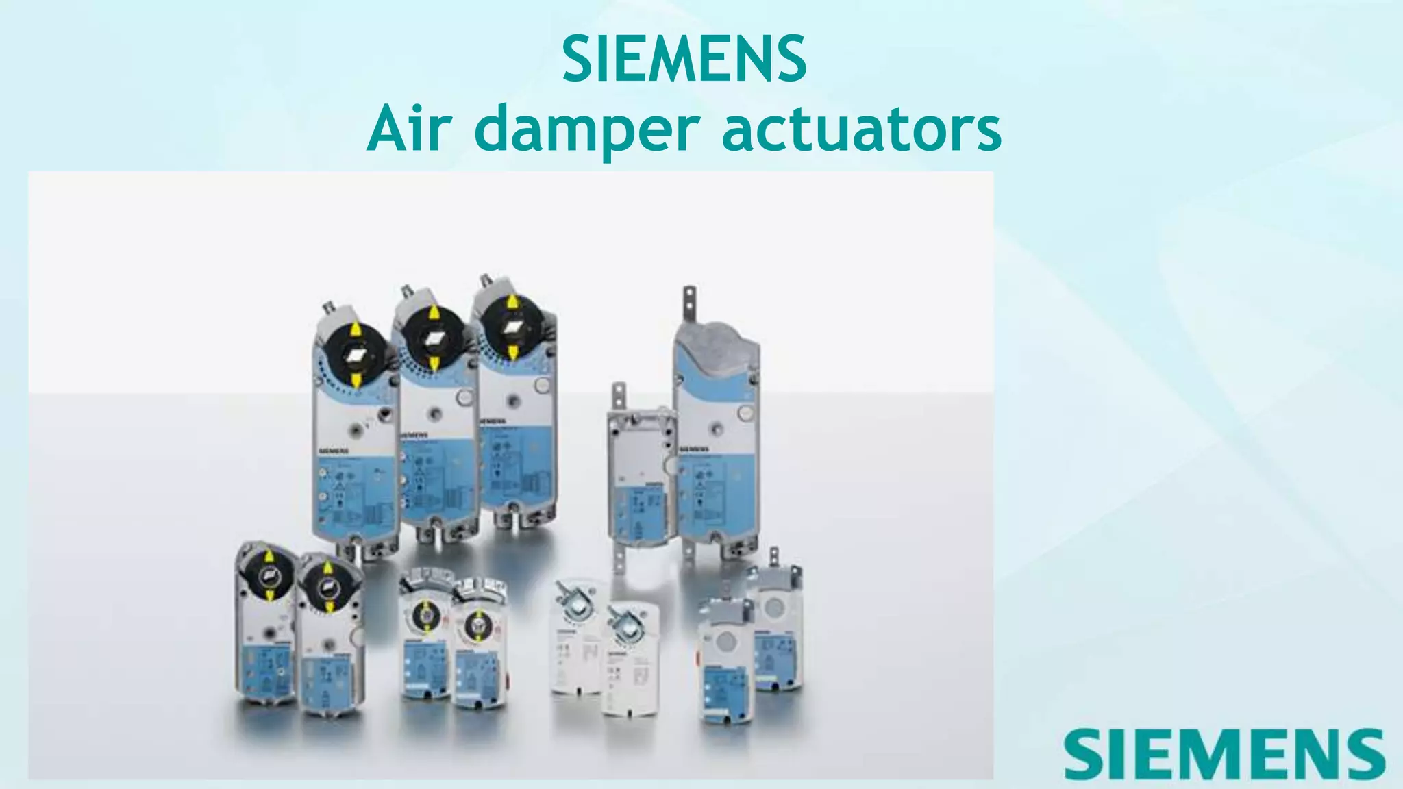
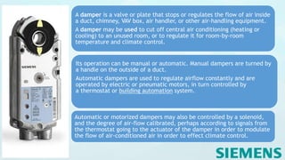
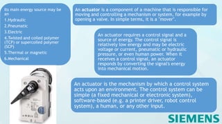
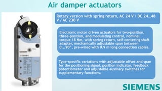
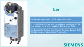
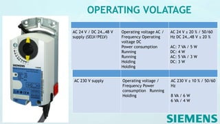
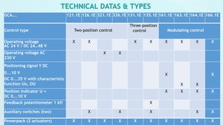
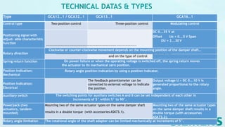
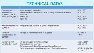
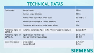
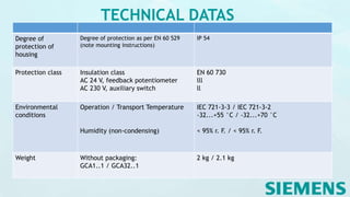
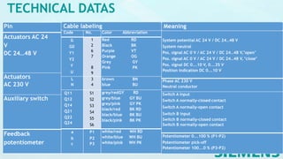
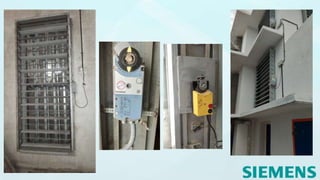

Siemens air damper actuators regulate airflow in HVAC systems using various control types, enabling both manual and automatic operation. They operate based on control signals and can be powered by electric, pneumatic, hydraulic, or thermal sources, providing precise climate control. The actuators include specific features such as torque specifications, operating voltages, position indicators, and auxiliary switches for enhanced functionality.


