Download to read offline

![Feature Specification
Setpoint Resolution 0.01 Hz Digital, 0.01 Hz Serial, 10 bit Analogue (motor
potentiometer 0.1 Hz [0.1% (in PID mode)])
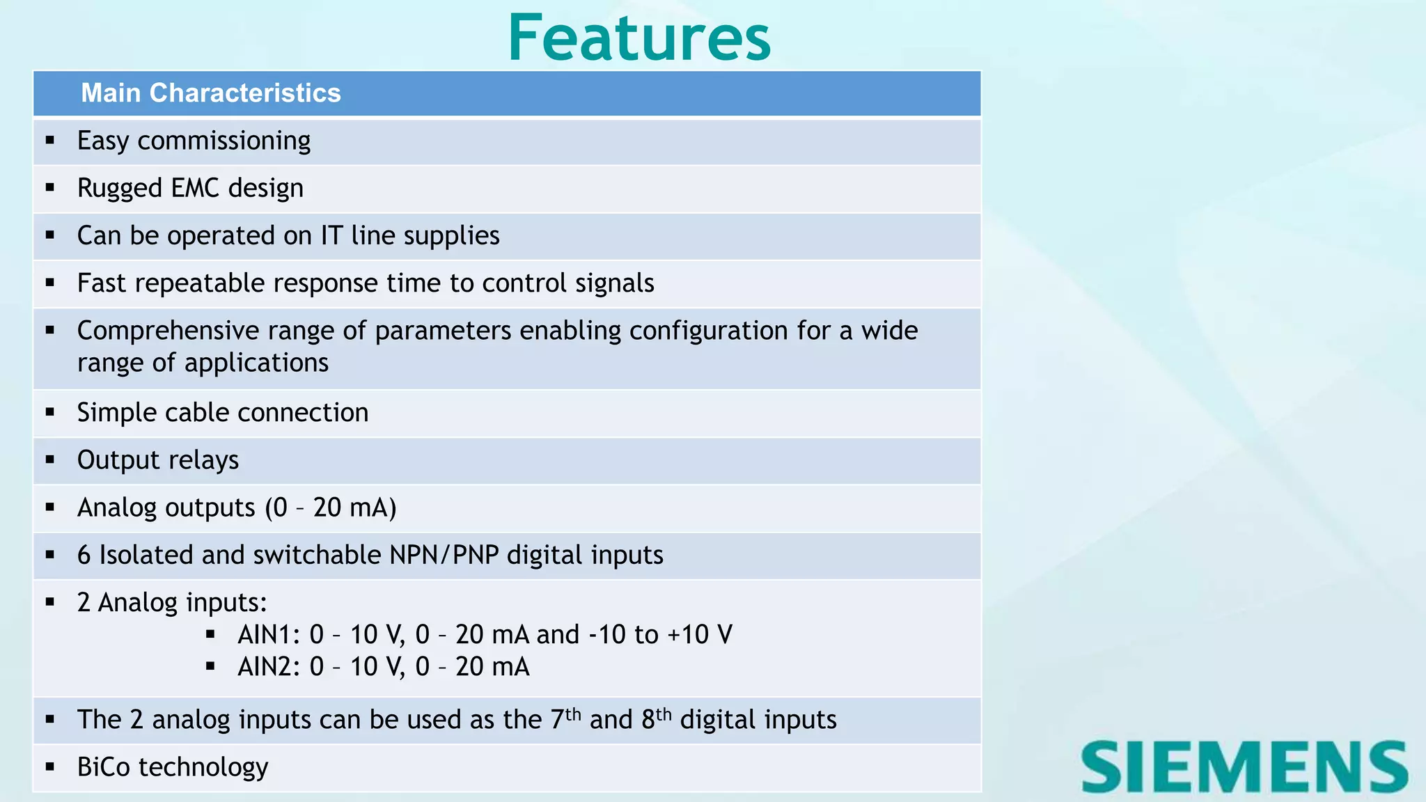
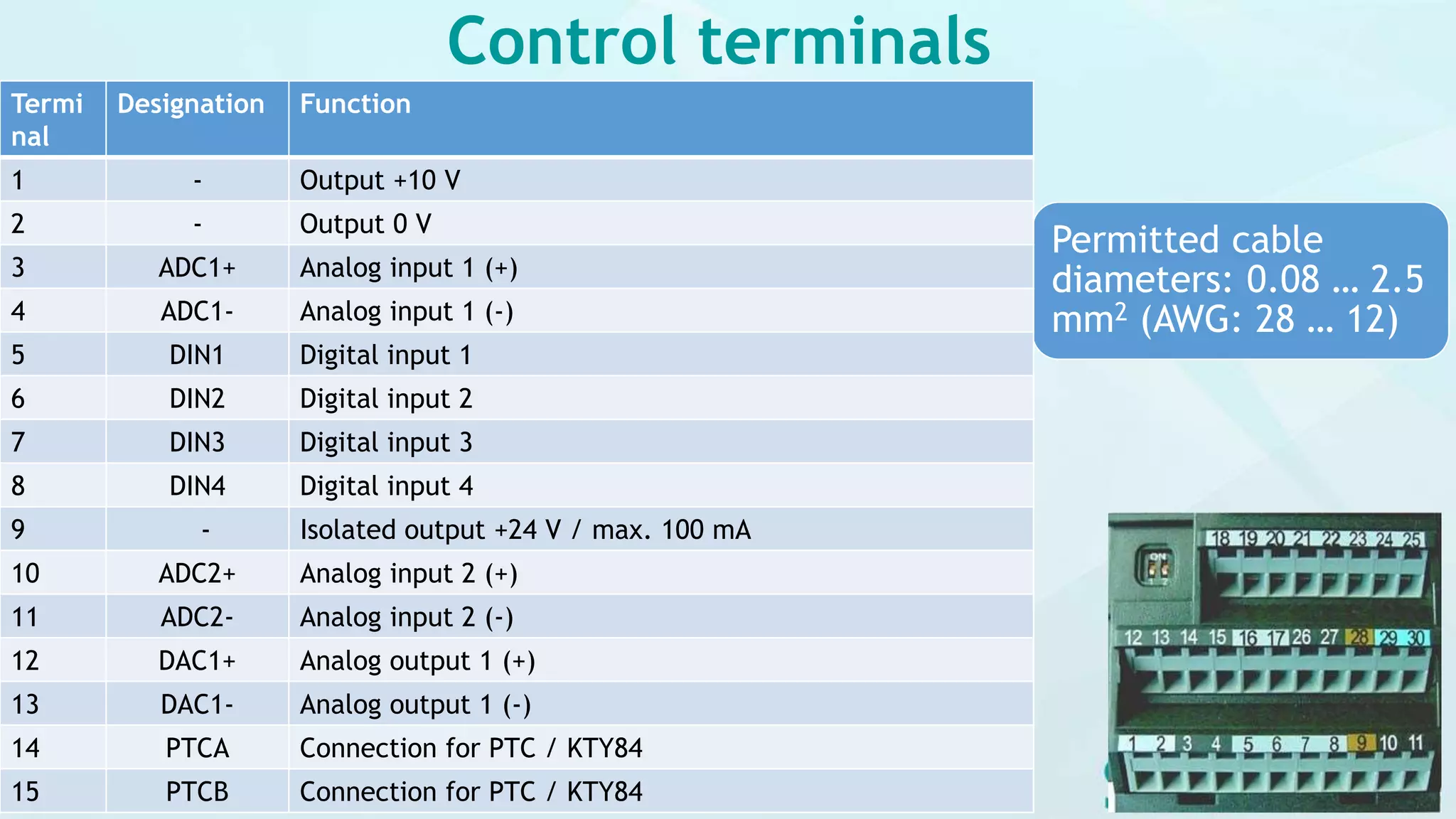
Digital Inputs 6, programmable (isolated), switchable active high / active low
(PNP/NPN)
Analog Input 1 0 - 10 V, 0 - 20 mA and –10 V to +10 V
Analog Input 2 0 - 10 V and 0 - 20 mA
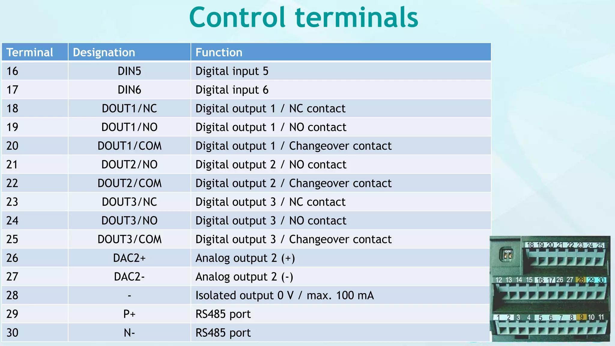
Relay Outputs 3, programmable 30 V DC / 5 A (resistive), 250 V AC 2 A (inductive)
Analogue Output 2, programmable (0 to 20 mA)
Serial Interface RS-485, optional RS-232
Braking DC braking, Compound braking
Technical data](https://image.slidesharecdn.com/siemensmicrovdfpart1-200615100148/75/Siemens-MICRO-VFD-part-1-16-2048.jpg)

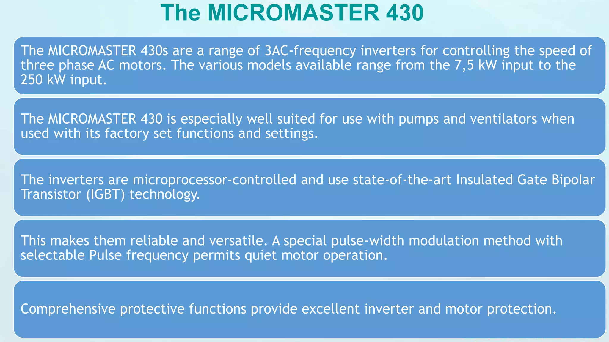
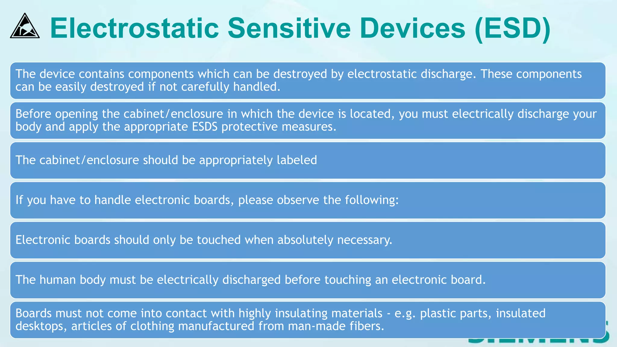
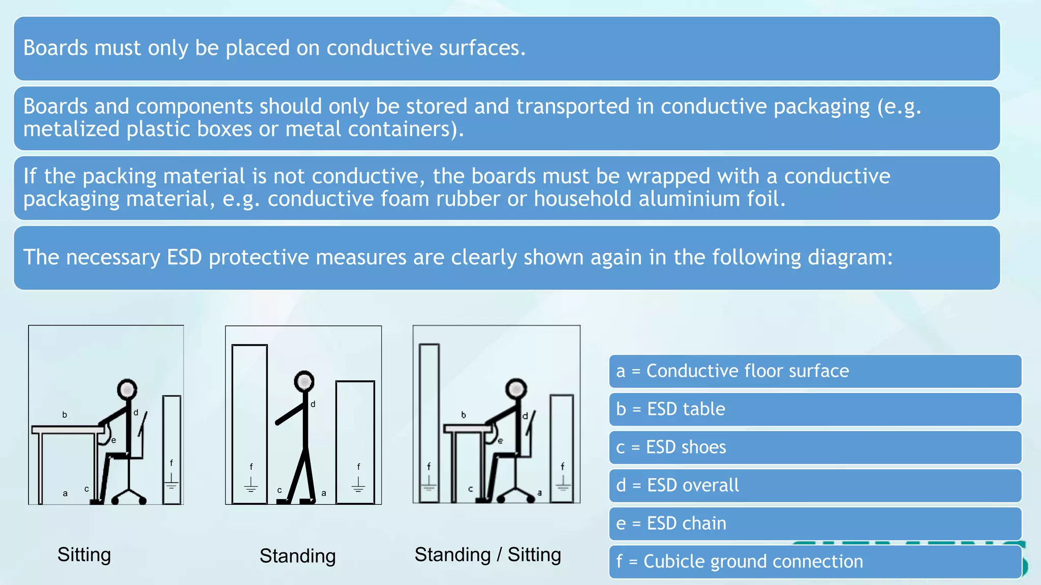
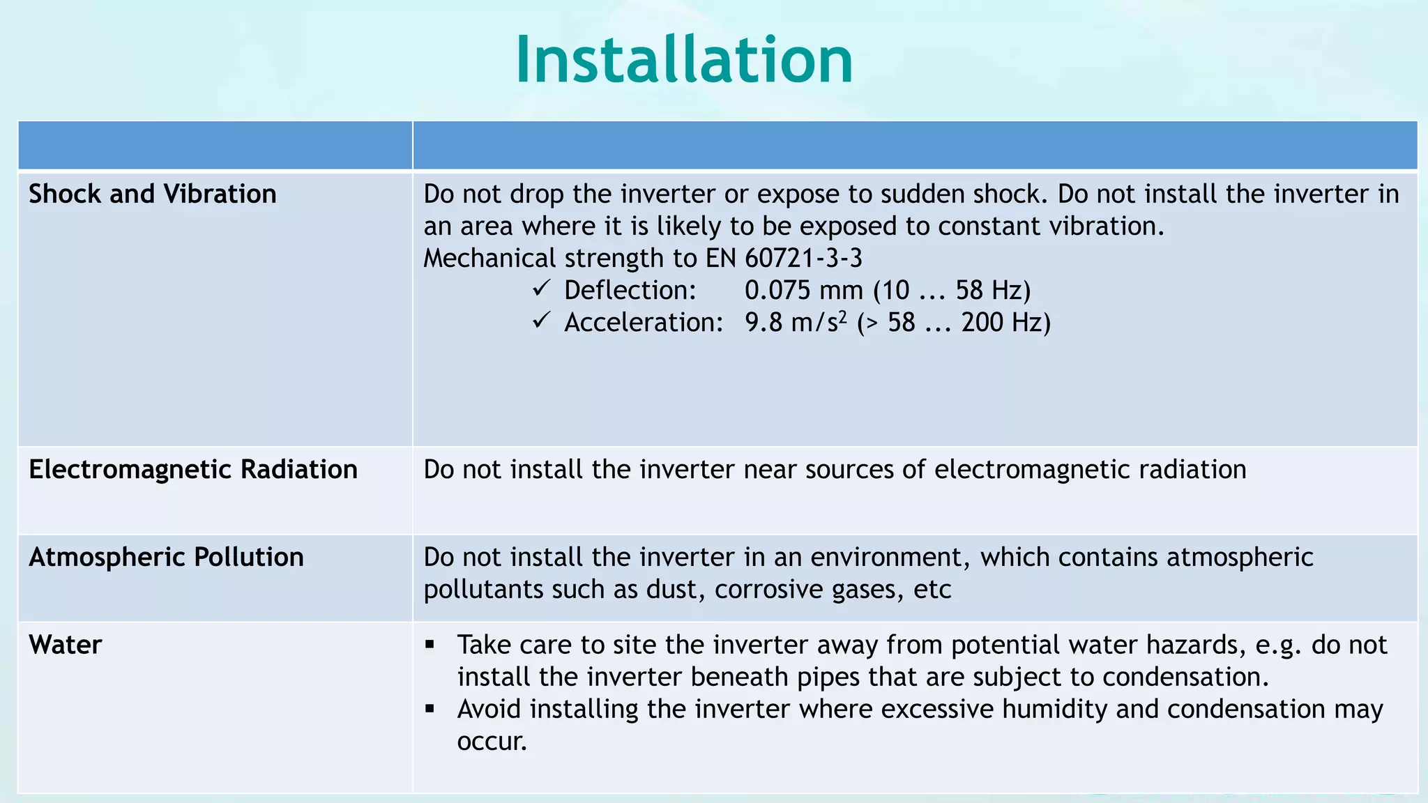
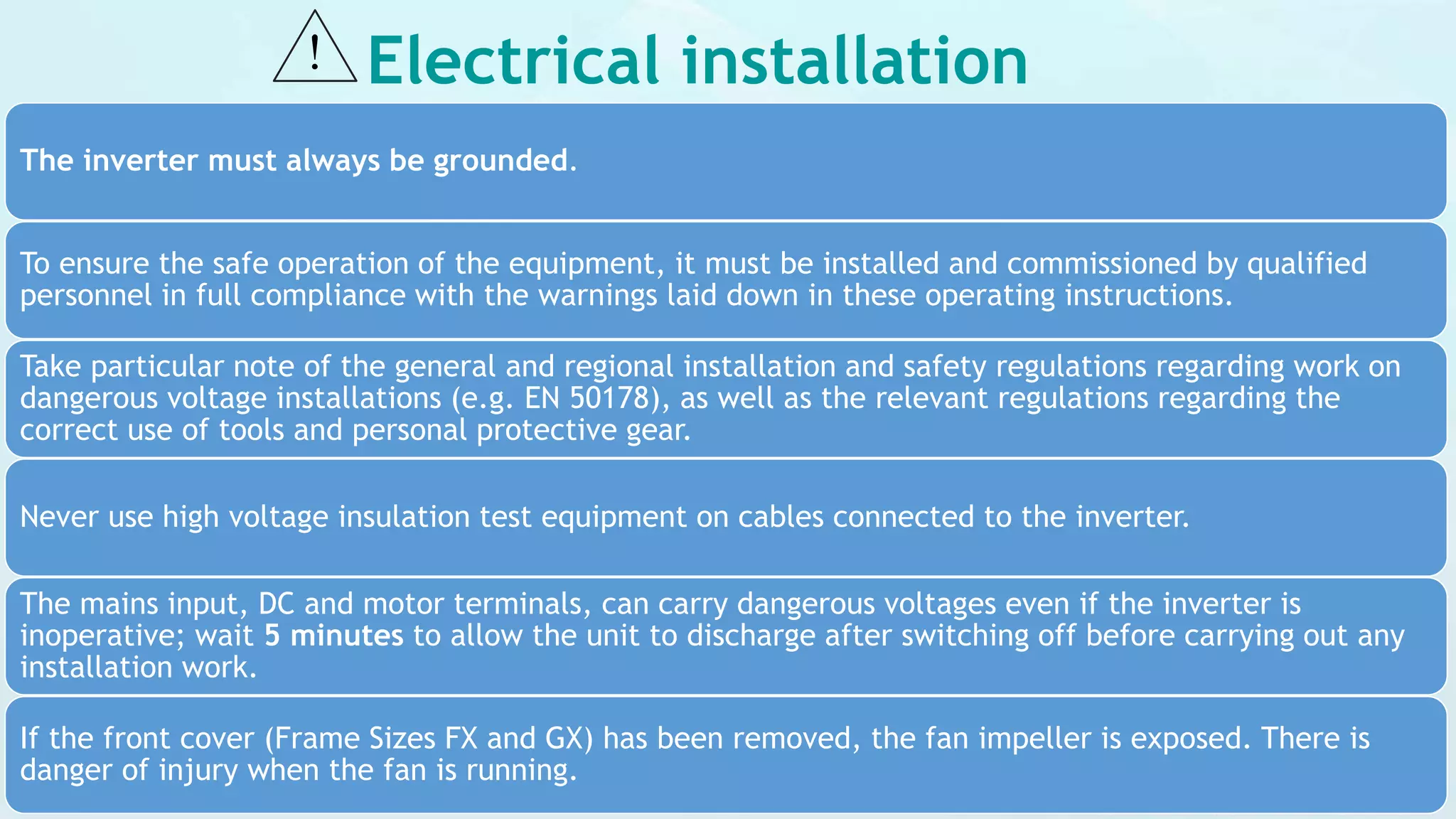
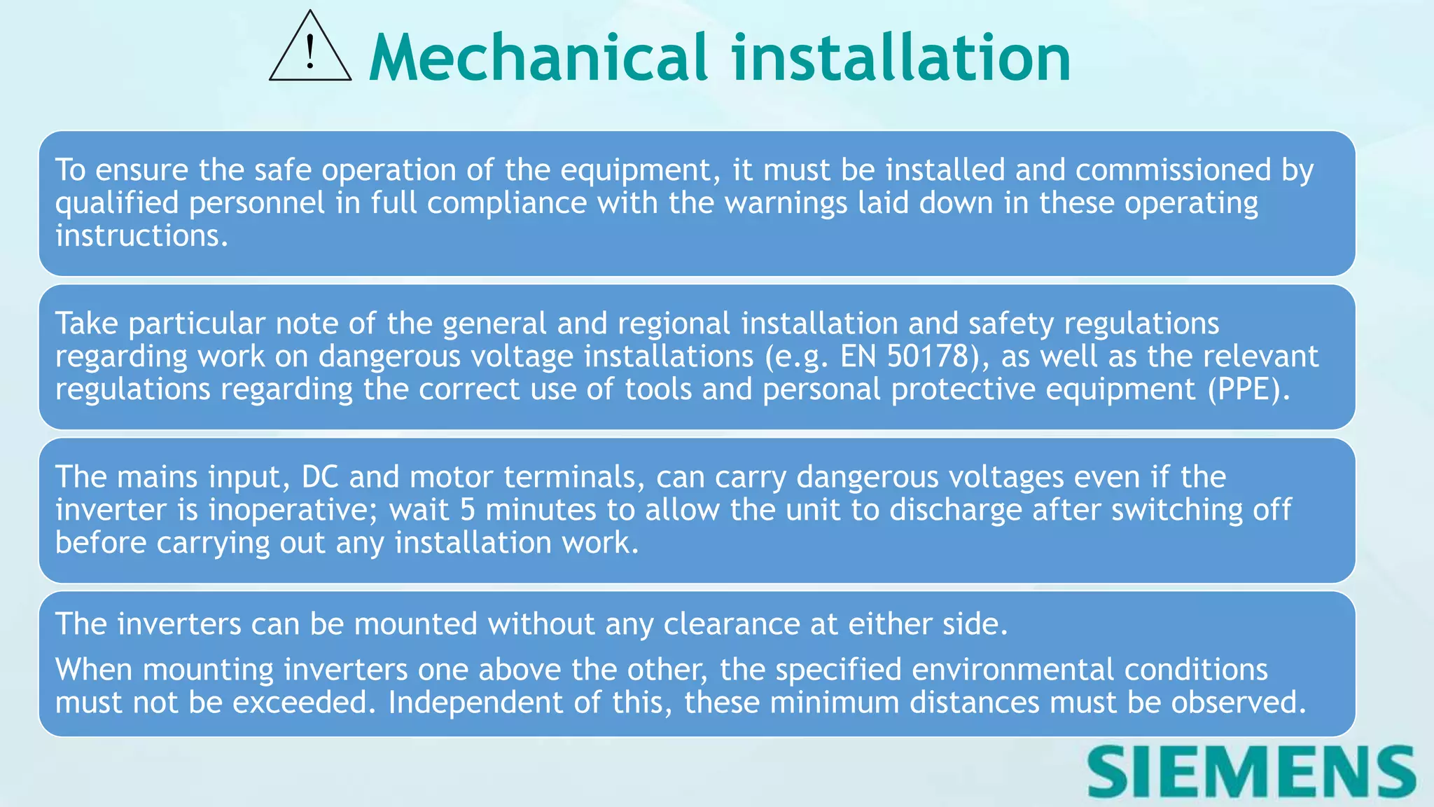
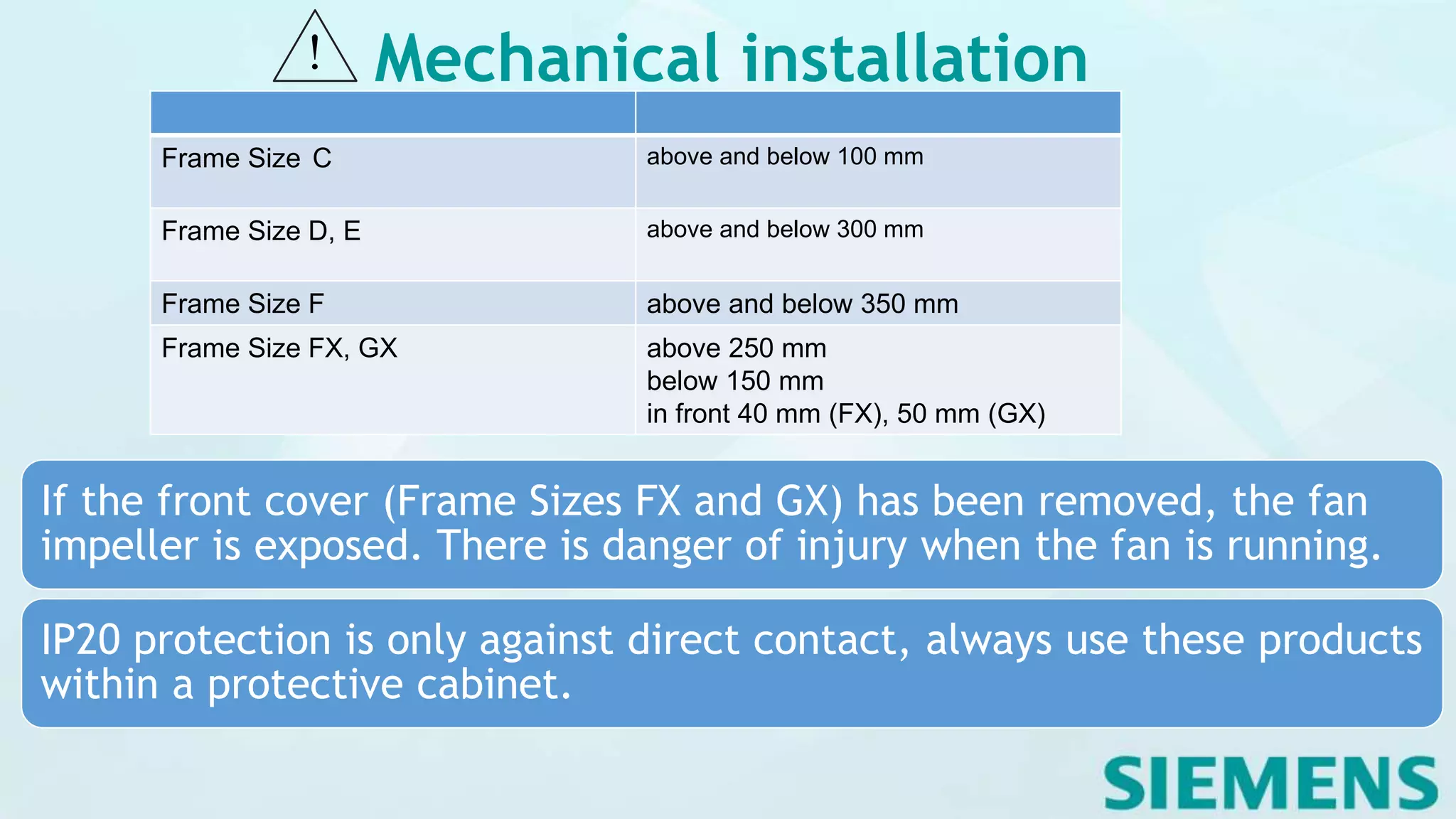
The Siemens Micromaster 430 is a range of 3AC-frequency inverters designed for controlling the speed of three-phase AC motors, suitable for applications like pumps and ventilators. It features microprocessor control, state-of-the-art IGBT technology, and a variety of protective functions while requiring careful handling to avoid electrostatic damage. Comprehensive installation guidelines are provided, emphasizing safety and compliance with regulations during setup.


