Download to read offline


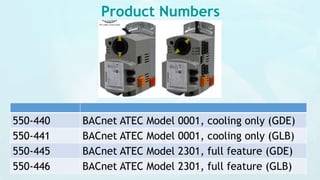
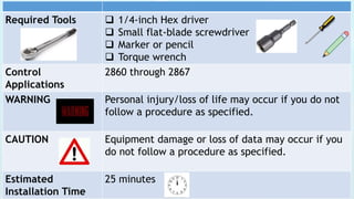
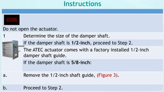
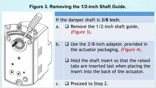


The document provides installation instructions for the Siemens BACnet Actuating Terminal Equipment Controller (ATEC), detailing the parts, required tools, and step-by-step procedures for mounting and configuring the actuator with various damper shaft sizes. It emphasizes safety precautions to prevent personal injury and equipment damage, along with wiring and configuration details for the actuator's digital outputs. Estimated installation time is 25 minutes, and the document includes figures to aid users in the installation process.


