Download to read offline
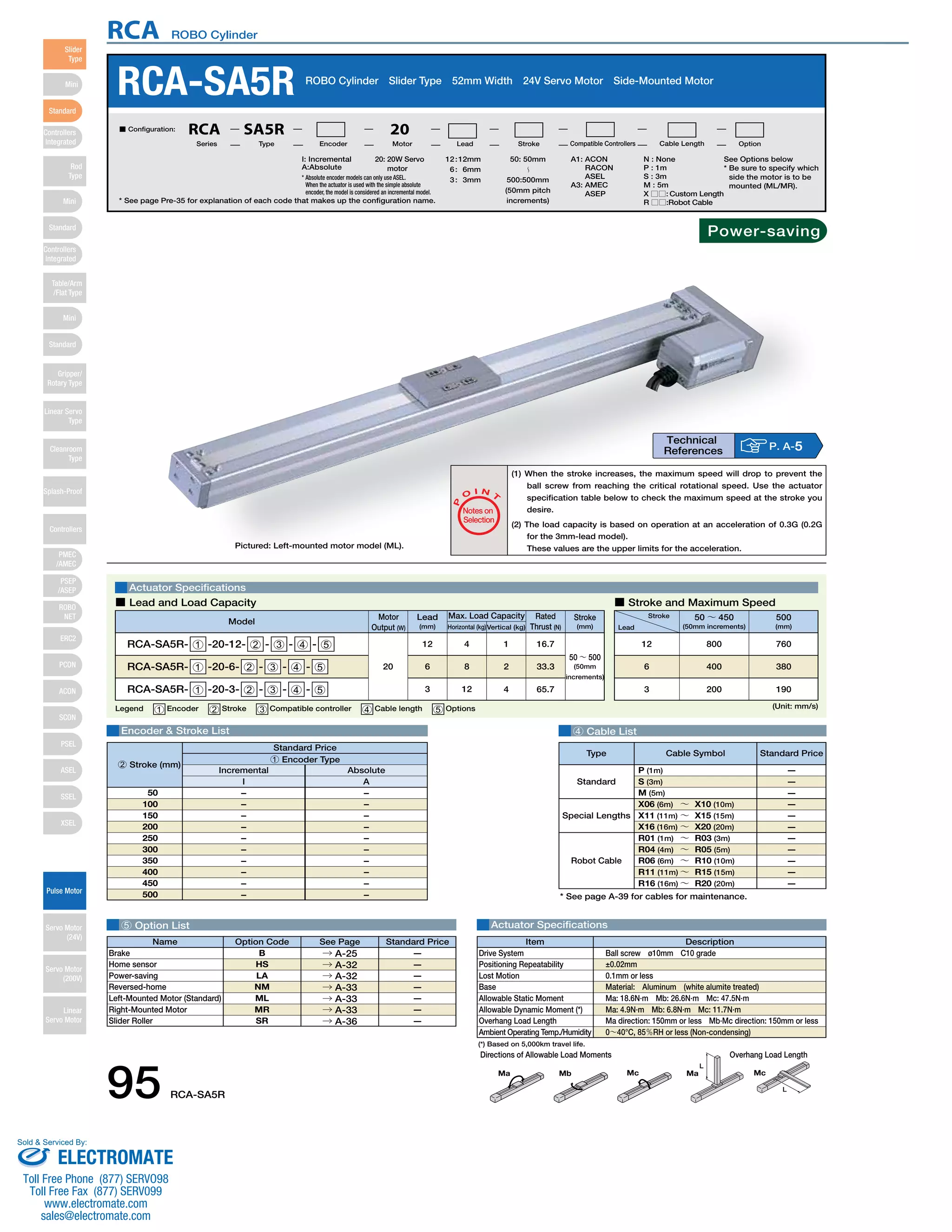
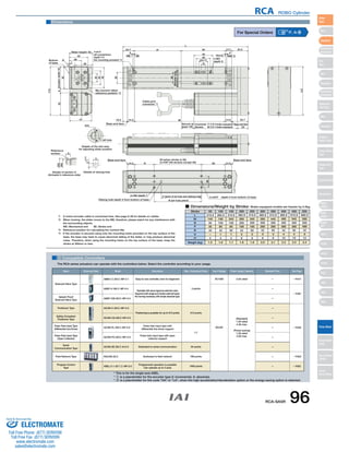

The document provides specifications for the RCA ROBO Cylinder actuator. It includes details on the actuator such as available strokes from 50mm to 500mm, motor options of 12V, 6V or 3V, and compatible controller options. Dimensional drawings and specifications are also provided to show the physical dimensions, load capacities, speeds and other technical details of the actuator. Compatible cable options and their prices are listed as well.