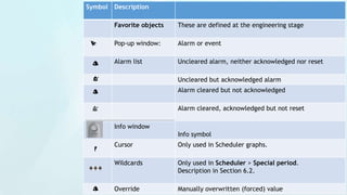
Download to read offline
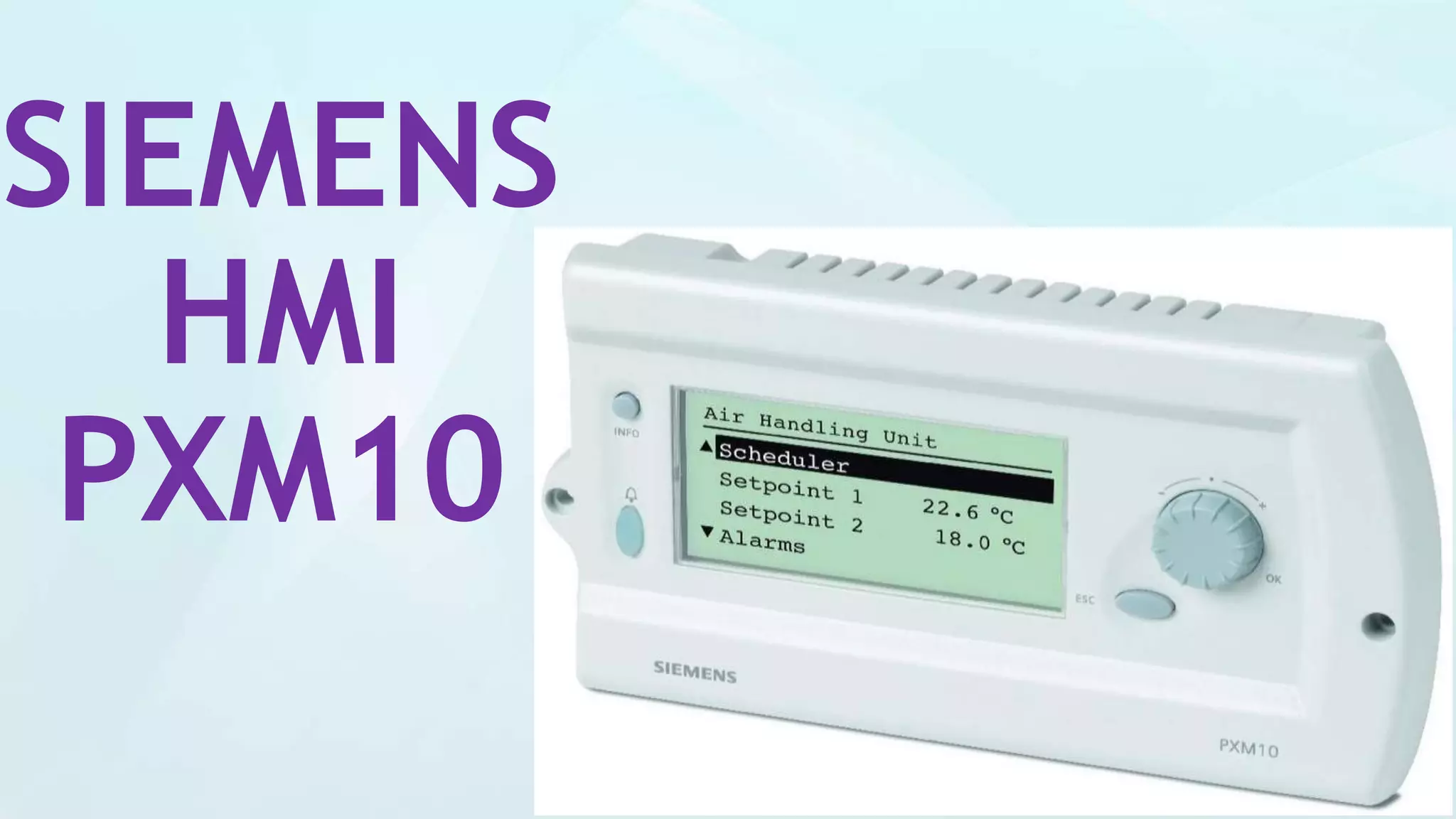
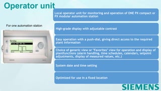
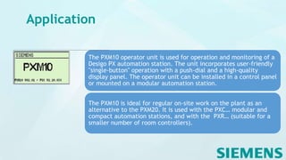
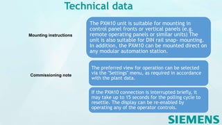
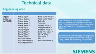
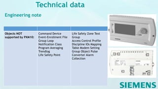
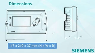
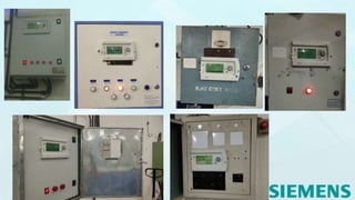

The Siemens PXM10 is a local operator unit designed for monitoring and operation of Desigo PX automation stations, featuring a high-grade display and user-friendly push-dial control. It allows for easy access to plant information, including alarms, schedules, and measured values, with options for a generic or favorites view. The unit is suitable for installation in control panels or mounted on automation stations and supports various input/output data types without storing user data itself.


