Download to read offline
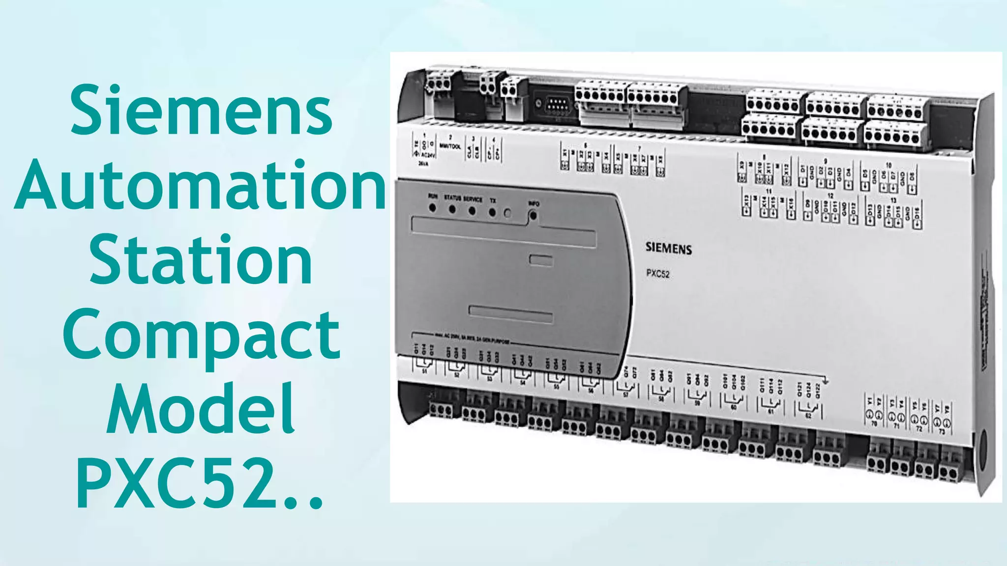


The Siemens PXC52 is a compact, programmable automation station designed for HVAC and building services systems, offering 52 physical data points per station, with functionalities including alarm management, time scheduling, and remote management. It features flexible communication capabilities via the BACnet protocol and can seamlessly interface with various field devices and operator units. The device is suitable for confined spaces and supports multiple inputs and outputs for effective system integration.


![Epi e epc [modo de compatibilidade]](https://cdn.slidesharecdn.com/ss_thumbnails/epieepcmododecompatibilidade-121116165554-phpapp02-thumbnail.jpg?width=640&height=640&fit=bounds)


