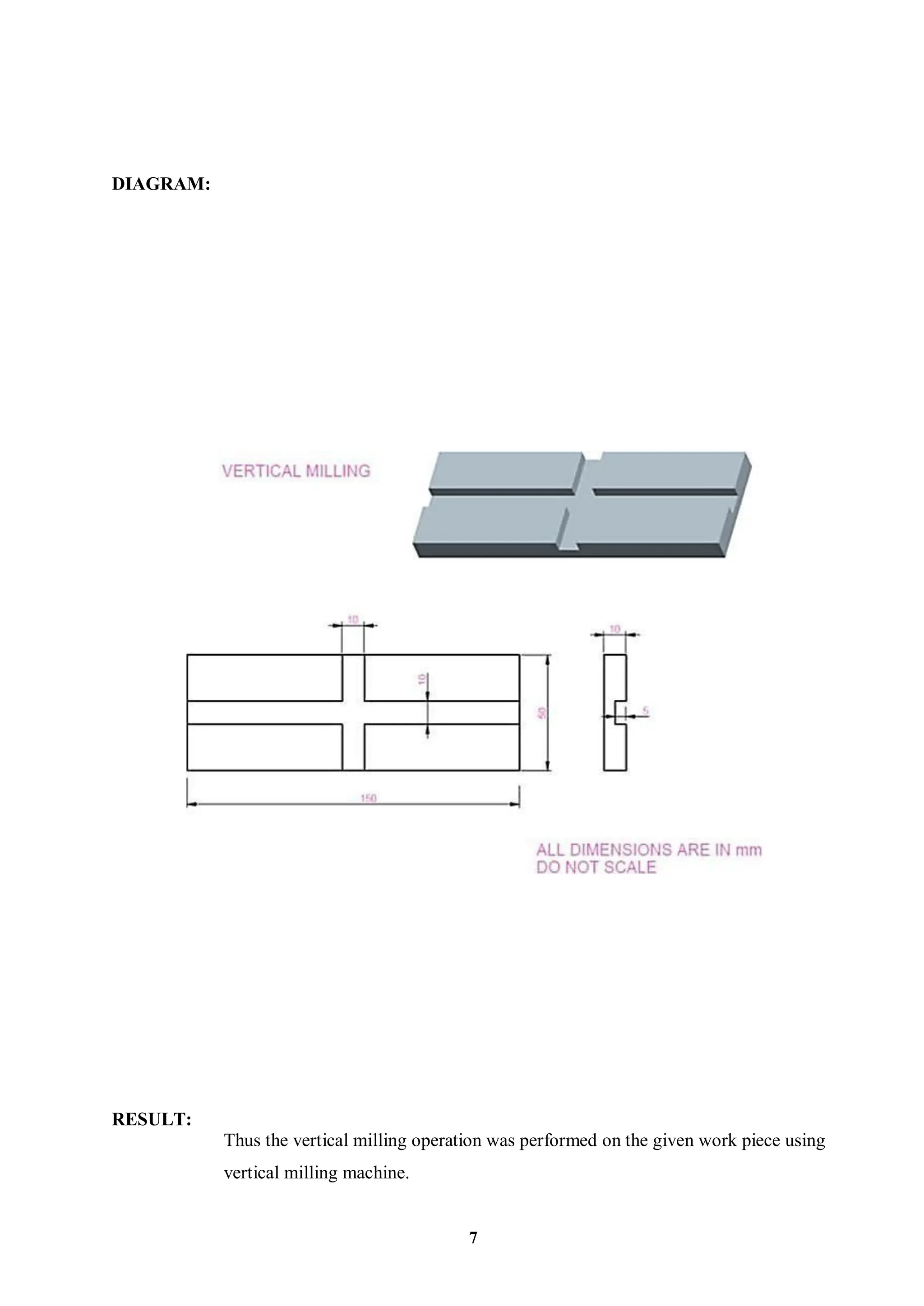
INTRODUCTION:
STUDY OF MILLINGMACHINE
Milling is the name given to the machining process in which the removal of metal
takes place due to cutting action of a revolving cutter when the work is fed past it. The
revolving cutter is held on a spindle and the work, clamped on the machine table, fed past the
same. Milling is the cutting operation that removes metal by feeding the work against a
rotating, cutter having single or multiple cutting edges. Flat or curved surfaces of many
shapes can be machined by milling with good finish and accuracy. A milling machine may
also be used for drilling, slotting, making a circular profile and gear cutting by having suitable
attachments.
WORKING PRINCIPLE IN MILLING:
The working principle, employed in the metal removing operation on a milling
machine, is revolving multi teeth cutter mounted either on a spindle. The cutter revolves at a
fairly high speed and the work fed slowly past the cutter. The work can be fed in a vertical,
longitudinal or cross direction. As the work advances, the cutter-teeth remove the metal from
the work surface to produce the desired shape. The work piece is holding on the worktable of
the machine. The table movement controls the feed of work piece against the rotating cutter.
The cutter is mounted on a spindle and revolves at high speed. Except for rotation the cutter
has no other motion. As the work piece advances, the cutter teeth remove the metal from the
surface of work piece and the desired shape is produced.
MILLING MACHINE
1
2
TYPES OF MILLING MACHINES:
A large variety of different types of milling machines is available. The classification of
these type machines can be done as follows:
1. Column and knee type milling machines
2. Fixed bed type or manufacturing type milling machines
3. Planer type milling machines
4. Production milling machines
5. Special purpose machines
COLUMN AND KNEE TYPE MILLING MACHINES:
These machines are all general purpose machines and have a single spindle only. They
are further classified as follows:
(a) Hand milling machine
(b) Plain or horizontal milling machine
(c) Vertical milling machine and
(d) Universal milling machine
3
FIXED BED TYPE OR MANUFACTURING TYPR MILLING MACHINE:
These machines, in comparison to the column and knee type, are more sturdy and rigid,
and heavier in weight and larger in size. Their further classification is as follows:
(a) Plain type (having single horizontal spindle).
(b) Duplex head (having double horizontal spindles).
(c) Triplex head (having two horizontal and one vertical spindle).
(d) Rise and fall type (for profile milling)
PLANER TYPE MILLING MACHINES:
They are used for heavy work. Up to a maximum of four tool heads can be mounted over
it, which can be adjusted vertically and transverse directions. It has a robust and massive
construction like a planar.
PRODUCTION MILLING MACHINES:
They are also manufacturing machines but differ from the above described machines in
that they do not have a fixed bed. They include following machines:
(a) Rotary table or continuous type.
(b) Drum type and
(c) Tracer controlled
SPECIAL PURPOSE MILLING MACHINES:
These machines are designed to perform a specific type of operation only. They include
following machines:
(a) Thread milling machine
(b) Profile milling machine
(c) Gear milling or gear hobbing machine
(d) Cam milling machine
(e) Planetary type milling machine
(f) Double end milling machine
(g) Skin milling machine and
(h) Spar milling machine.
4
PLAIN OR HORIZONTAL MILLING MACHINE
The vertical column serves as a housing for electrical, the main drive, spindle bearings,
etc. The knee acts as support for the saddle, worktable and other accessories like indexing
head, etc. Over arm provides support for the yoke which in turn, supports the free end of the
arbor. The arbor carrying the cutter rotates about a horizontal axis. The table can be given
straight motions in three directions; longitudinal, cross, vertical. For giving vertical
movement to the table the knee it, together with the whole unit above it, slides up and down
along the ways provide in front of the column. A brace is employed to provide additional
support and rigidity to the arbor when a long arbor is used. Both hand power and power feeds
can be employed for the work.
VERTICAL MILLING MACHINE:
It derives its name from the vertical position of the spindle. This is available in both
types; the fixed bed type as type as well as column and knee type. It carries a vertical column
on a heavy base. The over arm in this machine is made integral with the column and carries a
housing at its front. This housing called head can be of fixed type .In fixed type, the spindle
always remains vertical and can be adjusted up and down.
The knee carries an enclosed screw jack, by means of which it is moved up and down
along the parallel vertical guide ways provided on the front side of the column. The saddle is
mounted on the knee and can be moved, along the horizontal guide ways provided on the
knee, towards or away from the column. This enables the table to move in cross direction.
The work gets up and down movement by the knee, cross movement by saddle and
longitudinal movement by the table.
PARTS OF MILLING MACHINE:
Main parts of the milling machines are similar; all these machine essentials consist of the
following main parts:
1. BASE:
It is a heavy casting provided at the bottom of the machine. It is accurately
machined on both the top and bottom surfaces. It actually acts as a load bearing
member for all other parts of the machine. Also it carries the screw jack which
supports and moves the knee. In addition to this it also serves as reservoir for the
coolant.
2. COLUMN:
It is a very prominent part of the milling machine and is produced with enough
care. On the front face of the column are made the vertical parallel ways in which the
knee slides up and down. It carries the enclosed motor drive. Top of the column
carries dovetail horizontal ways for the over arm.
5
3. KNEE:
It is a rigid casting, which is capable of sliding up and down along the vertical
ways on the front face of the column. This enables the adjustment of the table height.
The adjustment is provided by operating the elevating jack, provided below the knee,
by means of hand wheel or application of power feed. For efficient operation of the
machine, rigidity of the knee and accuracy of its ways play an important role. On the
front face of the knee two bolts are usually provided for securing the braces to it to
ensure greater rigidity under heavy loads.
4. SADDLE:
It is the intermediate part between the knee and the table and acts as a support for
the latter. It can be adjusted crosswise, along the ways provided on the top of the
knee, to provide cross feed to the table. As its top, it carries horizontal ways, along
which moves the table during longitudinal traverse.
5. TABLE:
It acts as a support for the work. It is made of cast iron, with its top surface
accurately machined. Its top carries longitudinal cross T-slots to accommodate the
clamping bolts for fixing the work or securing the fixtures. Also, the cutting fluid,
after it is used, drains back to the reservoir through these slots and then the pipe fitted
for this purpose. Longitudinal feed is provided to it by means of hand wheel fitted on
one side of the feed screw. Cross feed is provided by moving the saddle and vertical
feed by raising or lowering the knee.
6. OVERARM:
It is the heavy support provided on the top of both plain and universal milling
machine. It can slide horizontally, along the ways provided on the top of the column,
and adjusted to a desired position in order to provide support to the projecting arbor
by accommodating its free end in the yoke.
6
AIM:
EX NO: 19 CONTOURMILLING USING VERTICAL MILLING MACHINE
To machine a groove in the given work piece using vertical milling machine.
TOOLS REQUIRED:
1. Milling machine
2. Vernier caliper
3. Steel rule
4. Machine vice
5. Centre punch
MATERIAL REQUIRED:
150 X 50 X 10 mm Cast Iron flat
PROCEDURE
1. Check whether the machine is in proper condition.
2. Check whether the work piece which gives in suitable size.
3. The job is marked to the desired shape and punched.
4. Hold the work piece in the vice and fix the tool in the arbor in correct position
and machine is started.
5. The minimum depth of cut is given and feed is given by reciprocating table.
6. Remove the job and check the dimensions.
7. Continue the steps to obtain required dimensions.
DIAGRAM:
RESULT:
Thus the vertical milling operation was performed on the given work piece using
vertical milling machine.
7
8
EX NO: 20 SPUR GEAR CUTTING IN MILLING MACHINE
AIM:
To machine gear to the given module and number of teeth in the given work piece.
TOOLS AND EQUIPMENTS REQUIRED:
1. Milling machine
2. Vernier caliper
3. Mandrel.
PROCEDURE:
1. Calculate the gear tooth proportions.
Where,
Blank diameter = (Z + 2) m
Tooth depth = 2.25 m
Tooth width = 1.5708 m
Z = Number of teeth required
m = module
Indexing calculation
Index crank movement = 40 / Z
2. The dividing head and the tail stock are bolted on the machine table. Their axis
must be set parallel to the machine table.
3. The gear blank is held between the dividing head and tailstock using a mandrel.
The mandrel is connected with the spindle of dividing head by a carrier and catch
plate.
4. The cutter is mounted on the arbor. The cutter is centered accurately with the
gear blank.
5. Set the speed and feed for machining.
6. For giving depth of cut, the table is raised till the periphery of the gear blank
just touches the cutter.
7. The micrometer dial of vertical feed screw is set to zero in this position.
8. Then the table is raised further to give the required depth of cut.
9. The machine is started and feed is given to the table to cut the first groove of the
blank.
10. After the cut, the table is brought back to the starting position.
11. Then the gear blank is indexed for the next tooth space.
12. This is continued till all the gear teeth are cut.
9
CALCULATION:
Z = No. of teeth = 23
m = module = 2 mm
Blank Diameter = (Z + 2) *m
= (23 + 2) *2
= 50 mm
Tooth Depth = 2.25m
= 2.25 *2
= 4.5 mm
Indexing Calculation
= 40 / Z
= 40 / 23
= 1.739
10
DIAGRAM:
RESULT:
Thus the required gear is machined using the milling machine to the required
number of teeth
11
EX NO: 21 HELICAL GEAR CUTTING IN MILLING MACHINE
AIM:
To make a helical gear from a CI blank using milling machine
MATERIAL REQUIRED:
Cast iron blank of Ф50mm
TOOLS REQUIRED:
1. Turning tool
2. Milling cutter (2mmmodule)
3. Vernier caliper(0-150mm)
4. Drilling tool Ф 10mm,Ф20mm
5. MandrelФ20mm
6. Spanner
7. Gear tooth Vernier
FORMULA:
Outer diameter = (N+2) M,
Module =OD/ (N+2),
No .of teeth = (OD/M) -2
N- Number of teeth M=module OD= outer diameter
PROCEDURE:
1. Turn the given CI bank to required diameter in Centre lathe.
2. Drill a hole in the blank of diameter equal to mandrel size.
3. Fix the blank between two centers of the dividing headusing mandrel.
4. Set the milling cutter on the machine spindle and select the suitable speed.
5. Raise the table (knee) vertically up until blank touches the cutter.
6. Calculate depth of cut and indexing calculation from module & number of teeth.
7. Give the depth of cut by raising the knee up.
8. According to index calculation set the dividing head.
9. Switch on the spindle and feed the blank against the rotating cutter by
reciprocating the table
10. Move the index arm on the index plate according to the calculated number of
holes.
11. Feed the blank against the rotating cutter to cut the next tooth.
12. Repeat the same for remaining teeth
12
DIAGRAM:
13
MODEL CALCULATION FOR HELICAL GEAR:
No of teeth (z) =30
Module (m) =2mm
External dia.of blank = (z+2)*m
= (30+2)*2=64
Depth of cut =2.25*m
=2.25*2
=4.5mm
The indexing crank rotation = one complete rotation and move arm holes in 33
concentric circle.
RESULT:
Thus the spur gear has made by using milling machine to the required size.
14
STUDY OF GEAR HOBBINGMACHINE
INTRODUCTION:
Gear Hobbing is a continuous generative process in which the tooth flanks of the
constantly moving work piece are formed by equally spaced cutting edges of the hob. The
profile produced on the gear is a curve comprising of a number of flats, varying with the
number of flutes in the hob which pass a given tooth during the generative movement. Every
hob tooth which contacts the gear along line of action produces one enveloping cut. Like the
straight flank of the hob tooth, the individual cut is straight and in tangent plane to the
involutes of the tooth flanking.
WORKING PRINCIPLE OF OPERATION:
The generative process requires an accurate relationship between various elements of the
machine in order to achieve the desired results. The work table rotates in a definite
relationship with the rotation of the hob. This relation is timed by index change gears. For
hobbing helical gears, the rotation of the work table is slightly advanced or retarded in
relation to the rotation of the axial feed screw by means of another set of change gears called
different change gears. The direction of feed of the hob relative to the work piece can be
achieved in any of the three ways, but these basic feeds can be combined to form other
permutations.
HOB Nomenclature
15
TYPES OF HOBBING:
The hobbing process is classified in to different types according to the directions of feeding
the hob for gear cutting.
1. HOBBING WITH AXIALFEED.
This type of feeding method is mainly used for cutting spur and helical gears, as
explained in the previous article. It involves moving the hob towards the gear blank or the
blank towards the hob to bring the two in such a relative position that the required tooth depth
is blank towards obtained .this is followed by feeding the rotating positions that the required
tooth depth is obtained. This is followed by feeding the rotating hob along the face of the
blank parallel to the axis of the latter. This feeding can be from below the blank upwards or
from above the blankupwards.
2. HOBBING WITH RADIALFEED.
This method of hob in-feed is mainly used for cutting worm wheels. In this method the
hob and gear blank are set with their axes normal tom each other. The gear blank continues to
rotate at a set speed about its vertical axis and the rotating hob is given in-feed in a radial,
direction towards the centre of blank rotation.
An important point to be noted here is that while the use of radial in feed results in higher
rate of production the accuracy of the tooth profile produced is of low order.
3. HOBBING WITH TANGENTIALFEED:
It is yet another common method used for cutting teeth on worm wheels. In this method,
the worm wheel blank is rotated in a vertical plane about horizontal axis. The hob is held with
its axis horizontal but at right angles to the axis of the blank. The hob in feed is tangential to
the blank face and hence, the name ‘tangentialfeeding’
ADVANTAGES:
1. It is a faster and continues process. Hence, quite economical as compared to other
generativeprocesses
2. It enables a high rate of production.
3. The gear teeth generated through this process are veryaccurate.
4. The process can be adopted with equal advantage for both medium and large batch
productions.
5. Hobbing machines, their setting and operation aresimpler.
16
EX NO: 22 GEAR GENERATION IN HOBBING MACHINE
AIM:
To generate a spur gear using Gear Hobbing machine to the given dimensions.
TOOLS REQUIRED:
1. Vernier caliper
2. Mandrel
3. Drill bitø25mm
PROCEDURE:
1. The given job is turned to required outer diameter
2. The given job is held firmly in the mandrel against the gear Hobber
3. The position of work table is adjusted, so that the job and cutter are onthe
same line
4. The machine is switched ON and the table is fed parallel to the cutter.
5. The feed is given longitudinally again and again, this procedure is repeated for
completion of 16teeth.
17
DIAGRAM:
RESULT:
Thus the spur gear is generated using Gear Hobbing machine
18
AIM:
STUDY OF GEARSHAPING MACHINE
To study the working of gear shaping machine
INTRODUCTION
A gear shaper is a machine tool for cutting the teeth of internal or external gears. The
name shaper relates to the fact that the cutter engages the part on the forward stroke and pulls
away from the part on the return stroke, just like the clapper box on a planer shaper.
The cutting tool is also gear shaped having the same pitch as the gear to be cut.
However number of cutting teeth must be less than that of the gear to be cut for internal gears.
For external gears the number of teeth on the cutter is limited only by the size of the shaping
machine. For larger gears the blank is sometimes gashed to the rough shape to make shaping
easier.
The principal motions involved in rotary gear shaper cutting are of the following
1. Cutting Motion: The downward linear motion of the cutter spindle together with the
cutter.
2. Return Stroke: The upward linear travel of the spindle and cutter to withdraw the
latter to its starting position.
3. Indexing Motion: Slow speed continuous rotation of the cutter spindle and work
spindle to provide circular feed, the two speeds being regulated through the change
gears such that against each rotation of the cutter the gear blank revolves through n/N
revolution, where "n" is the number of teeth of the cutter, and "N" is the number of
teeth to be cut on the blank.
4. Completion of Cutting Operation: The indexing and reciprocating motions continue
until the required number of teeth to the required depth are cut all along the periphery
of the gear blank
WORKING PRINCIPLE OF OPERATION
Gear shaping is similar to the rack type cutting process, excepting that, the linear type
rack cutter is replaced by a circular cutter as indicated in figure, where both the cutter and the
blank rotate as a pair of spur gears in addition to the reciprocation of the cutter Generation
method is characterized by automatic indexing and ability of a single cutter to cover the
entire range of number of teeth for a given combination of module and pressure angle and
hence provides high productivity and economy.
The gear type cutter is made of HSS and possesses proper rake and clearance angles. The
additional advantages of gear shaping over rack type cutting are:
• Separate indexing is not required at all
• Straight or helical teeth of both external and internal spur gears can be
produced with high accuracy and finish
• Productivity is also higher
Result:
Thus the working of gear shaping machine has been studied
19
AIM:
EX NO:23 GEAR GENERATION IN GEAR SHAPING MACHINE
To make a Spur Gear form a CI blank using Gear Shaping machine.
MATERIAL REQUIRED:
Cast iron blank of Ф50mm
TOOLS REQUIRED:
1. Vernier caliper
2. Mandrel
3. Drill bitø25mm
PROCEDURE:
1. The given job is turned to required outer diameter
2. The given job is held firmly in the mandrel against the Gear Shaping machine.
3. The position of work table is adjusted, so that the job and cutter are on the
same line
4. The machine is switched ON and the table is fed parallel to the cutter.
5. The feed is given longitudinally again and again, this procedure is repeated for
completion of 16teeth.
DIAGRAM:
RESULT:
Thus the Spur Gear is Generated using Gear Shaping machine
20
21
STUDY OF GRINDINGMACHINE
INTRODUCTION:
Grinding is metal cutting operation performed by means of a rotating abrasive wheel
that acts as a tool. This is used to finish work pieces which must show a high surface quality,
accuracy of shape and dimension. The art of grinding goes back many centuries. Columns
and statues were shaped and finished with a globular stone which abraded the surface.
Mostly grinding is a finishing operation because it removes comparatively little metal
0.25 to 0.50 mm in most operations and the accuracy is in the order of 0.000025 mm. many
different types of grinding machines have now been developed for handling various kinds of
work to which the grinding process is applicable. A grinding machine is a machine tool used
for grinding, which is a type of machining using an abrasive wheel as the cutting tool. Each
grain of abrasive on the wheel's surface cuts a small chip from the work piece via shear
deformation.
The grinding machine consists of a power driven grinding wheel spinning at the
required speed and a bed with a fixture to guide and hold the work-piece. The grinding head
can be controlled to travel across a fixed work piece or the work piece can be moved whilst
the grind head stays in a fixed position. Very fine control of the grinding head or table
position is possible using a Vernier calibrated hand wheel, or using the features of numerical
controls. Grinding machines remove material from the work piece by abrasion, which can
generate substantial amounts of heat; they therefore incorporate a coolant to cool the work
piece so that it does not overheat and go outside its tolerance. The coolant also benefits the
machinist as the heat generated may cause burns in some cases.
22
KINDS OF GRINDING:
1. Rough or non-precision grinding
2. Precision grinding
ROUGH OR NON PRECISION GRINDING
The common forms of rough grinding are snagging and offhand grinding, where the
work is held in the operator’s hand. The work is pressed hard against the wheel, or vice versa.
The accuracy and surface finish obtained of secondary importance.
PRECISION GRINDING
This is concerned with producing good surface finish and high degree of accuracy.
Yarn wheel or work both are guided in precise paths.
CENTRELESS GRINDERS
Centre less grinding is a method of grinding exterior cylindrical tapered and formed
surfaces on work pieces that are not held and rotated on centers. The principle elements of an
external center less grinder are the grinding wheel, regulating or back up wheel and the work
rest. Both wheels are rotated in the same direction. The work rest is located between the
wheels. The work is placed upon the work rest and the latter together with the regulating
wheel, is fed forward forcing the work against the grinding wheel. Centre less grinding may
be done in one of the three ways
a) Through feed
b) In feed
c) End feed
SURFACE GRINDERS:
Surface grinding machines are employed to finish planes on flat surfaces. They are
also capable of grinding irregular, curved, convex and concave surfaces. Conventional
surface grinders may be divided into two classes: one class has reciprocating tables for work
ground along straight lines, while the other covers the machines with rotating work tables
continuous rapid grinding. Surface grinders may also are classified according to whether they
have horizontal or vertical grinding wheel spindles.
Horizontal Spindle Reciprocating Table Surface Grinder:
 Base: The base has a column at the back for supporting the wheel head. The base also
contains the drive mechanism.
 Table: The table is fitted to the saddle on carefully machined ways. It reciprocates along
ways to provide the longitudinal feed. If slots are provided in the table surfaces for
clamping work pieces directly on the table or for clamping grinding fixtures or a magnetic
chuck;
 Wheel Head: The wheel heads are mounted on the column secured on the base. It has
ways for the vertical slide which can be raised or lowered with the grinding wheel only
manually by rotating a hand wheel to accommodate work pieces of different heights and to
set the wheel for depth of cut.
 Operation: The work piece reciprocates under the wheel, and the wheel on the table beds
axially between passes to produce a fine flat surface. Wheel down feed determines depth of
cut and final height of the piece from the table to the wheel. The amount of feed must only
be equal to a few hundredths of milling meters. For example steel is rough ground
withadepthofcutbetween0.02and0.05mmandfinishgroundwithadepthofcutof
0.005 to 0.01mm.
23
EX NO: 24 PLAIN SURFACE GRINDING
AIM:
To finish the surface of the given specimen using surface grinding machine
TOOLS REQUIRED:
1. Magnetic power machine table
2. Vernier caliper(0-150mm)
3. Micrometer(0-25mm)
4. Aluminum oxide grinding wheel.
MATERIAL REQUIRED:
100mmΧ50mmΧ6mm M.S. flat
PROCEDURE
1. Check the dimensions of the given flat.
2. Mark the dimensions as per the given drawing using steel rule and scriber.
3. Clamp the work piece by means of a magnetic chuck.
4. Then start the machine with slow speed
5. The table is started to Reciprocate.
6. Then feed is given with minimum depth of cut.
7. Remove the job and check the dimensions.
8. Continue the steps to achieve the required dimensions.
24
DIAGRAM:
RESULT:
Thus the surface grinding operation is performed on the work piece.
25
AIM:
EX NO: 25 CYLINDRICAL GRINDING
To grind a given cylindrical work piece by using cylindrical grinding machine as per
dimensions in the drawing
TOOLS REQUIRED:
1. Dog carrier
2. Vernier caliper
3. Vernier height gauge
4. Chuck key
5. Double ended spanner
6. V-block
7. Punch and Hammer
MATERIAL SUPPLIED:
1. Φ25mmХ100mm cylindrical work piece
2. Material mild steel
PROCEDURE:
1. Check the dimensions of the given workpiece.
2. Mark the dimensions as per the given drawing using steel rule and scriber.
3. Make drilling on both side of the marked center.
4. Hold the job in dog carrier and between the centers to remove the excess material
from the workpiece.
5. Grind the work piece of given dimension.
6. Check the dimension of the job.
DIAGRAM:
RESULT:
Thus the cylindrical grinding is operation performed on the work piece.
26
EX NO: 26 MEASUREMENT OF CUTTING FORCES IN MILLING/ TURNING PROCESS
AIM:
To measure the cutting forces for the given cutting conditions
TOOLS AND EQUIPMENTS REQUIRED:
1. Lathe
2. Lathe Tool Dynamometer
PROCEDURE:
1. The Lathe Tool Dynamometer is initially set to zero reading.
2. The known depth of cut is given and take the readings of Px and Pz force
components from the Lathe Tool Dynamometer.
3. Calculate the resultant cutting force
P= √𝑃𝑥2
+ 𝑃𝑧2
4. Repeat the same procedure to get few more readings and calculate the mean cutting
force.
5. Repeat the same procedure for different depth of cuts
NOTE:
1. Pz – the main or tangential component, determines the torque on main drive mechanism,
the deflection of the tool and the required power. This component acts in the direction of the
cuttingspeed.
2. Px – the axial component, acts in the direction of the tool traverse and it is at right angles
to Pz. It contributes very little to the power consumption.
3. Py – the radial component, acts along the tool shank and perpendicular to the other two
components. It has no share in the powerconsumption
DIAGRAM:
TABULATION :
S.No
Depth of
Cut
(mm)
Horizontal
Component
(Kg)
Vertical
Component
(Kg)
Resultant
P= √𝑷𝒙𝟐 +
𝑷𝒛𝟐
(Kg)
AVERAGE
(Kg)
1. 0.25
2. 0.50
3. 0.75
RESULT:
Thus the cutting forces are measured for different depth of cut
MT-II Lab Manual.pdf

MT-II Lab Manual.pdf

  • 1.
    INTRODUCTION: STUDY OF MILLINGMACHINE Millingis the name given to the machining process in which the removal of metal takes place due to cutting action of a revolving cutter when the work is fed past it. The revolving cutter is held on a spindle and the work, clamped on the machine table, fed past the same. Milling is the cutting operation that removes metal by feeding the work against a rotating, cutter having single or multiple cutting edges. Flat or curved surfaces of many shapes can be machined by milling with good finish and accuracy. A milling machine may also be used for drilling, slotting, making a circular profile and gear cutting by having suitable attachments. WORKING PRINCIPLE IN MILLING: The working principle, employed in the metal removing operation on a milling machine, is revolving multi teeth cutter mounted either on a spindle. The cutter revolves at a fairly high speed and the work fed slowly past the cutter. The work can be fed in a vertical, longitudinal or cross direction. As the work advances, the cutter-teeth remove the metal from the work surface to produce the desired shape. The work piece is holding on the worktable of the machine. The table movement controls the feed of work piece against the rotating cutter. The cutter is mounted on a spindle and revolves at high speed. Except for rotation the cutter has no other motion. As the work piece advances, the cutter teeth remove the metal from the surface of work piece and the desired shape is produced. MILLING MACHINE 1
  • 2.
    2 TYPES OF MILLINGMACHINES: A large variety of different types of milling machines is available. The classification of these type machines can be done as follows: 1. Column and knee type milling machines 2. Fixed bed type or manufacturing type milling machines 3. Planer type milling machines 4. Production milling machines 5. Special purpose machines COLUMN AND KNEE TYPE MILLING MACHINES: These machines are all general purpose machines and have a single spindle only. They are further classified as follows: (a) Hand milling machine (b) Plain or horizontal milling machine (c) Vertical milling machine and (d) Universal milling machine
  • 3.
    3 FIXED BED TYPEOR MANUFACTURING TYPR MILLING MACHINE: These machines, in comparison to the column and knee type, are more sturdy and rigid, and heavier in weight and larger in size. Their further classification is as follows: (a) Plain type (having single horizontal spindle). (b) Duplex head (having double horizontal spindles). (c) Triplex head (having two horizontal and one vertical spindle). (d) Rise and fall type (for profile milling) PLANER TYPE MILLING MACHINES: They are used for heavy work. Up to a maximum of four tool heads can be mounted over it, which can be adjusted vertically and transverse directions. It has a robust and massive construction like a planar. PRODUCTION MILLING MACHINES: They are also manufacturing machines but differ from the above described machines in that they do not have a fixed bed. They include following machines: (a) Rotary table or continuous type. (b) Drum type and (c) Tracer controlled SPECIAL PURPOSE MILLING MACHINES: These machines are designed to perform a specific type of operation only. They include following machines: (a) Thread milling machine (b) Profile milling machine (c) Gear milling or gear hobbing machine (d) Cam milling machine (e) Planetary type milling machine (f) Double end milling machine (g) Skin milling machine and (h) Spar milling machine.
  • 4.
    4 PLAIN OR HORIZONTALMILLING MACHINE The vertical column serves as a housing for electrical, the main drive, spindle bearings, etc. The knee acts as support for the saddle, worktable and other accessories like indexing head, etc. Over arm provides support for the yoke which in turn, supports the free end of the arbor. The arbor carrying the cutter rotates about a horizontal axis. The table can be given straight motions in three directions; longitudinal, cross, vertical. For giving vertical movement to the table the knee it, together with the whole unit above it, slides up and down along the ways provide in front of the column. A brace is employed to provide additional support and rigidity to the arbor when a long arbor is used. Both hand power and power feeds can be employed for the work. VERTICAL MILLING MACHINE: It derives its name from the vertical position of the spindle. This is available in both types; the fixed bed type as type as well as column and knee type. It carries a vertical column on a heavy base. The over arm in this machine is made integral with the column and carries a housing at its front. This housing called head can be of fixed type .In fixed type, the spindle always remains vertical and can be adjusted up and down. The knee carries an enclosed screw jack, by means of which it is moved up and down along the parallel vertical guide ways provided on the front side of the column. The saddle is mounted on the knee and can be moved, along the horizontal guide ways provided on the knee, towards or away from the column. This enables the table to move in cross direction. The work gets up and down movement by the knee, cross movement by saddle and longitudinal movement by the table. PARTS OF MILLING MACHINE: Main parts of the milling machines are similar; all these machine essentials consist of the following main parts: 1. BASE: It is a heavy casting provided at the bottom of the machine. It is accurately machined on both the top and bottom surfaces. It actually acts as a load bearing member for all other parts of the machine. Also it carries the screw jack which supports and moves the knee. In addition to this it also serves as reservoir for the coolant. 2. COLUMN: It is a very prominent part of the milling machine and is produced with enough care. On the front face of the column are made the vertical parallel ways in which the knee slides up and down. It carries the enclosed motor drive. Top of the column carries dovetail horizontal ways for the over arm.
  • 5.
    5 3. KNEE: It isa rigid casting, which is capable of sliding up and down along the vertical ways on the front face of the column. This enables the adjustment of the table height. The adjustment is provided by operating the elevating jack, provided below the knee, by means of hand wheel or application of power feed. For efficient operation of the machine, rigidity of the knee and accuracy of its ways play an important role. On the front face of the knee two bolts are usually provided for securing the braces to it to ensure greater rigidity under heavy loads. 4. SADDLE: It is the intermediate part between the knee and the table and acts as a support for the latter. It can be adjusted crosswise, along the ways provided on the top of the knee, to provide cross feed to the table. As its top, it carries horizontal ways, along which moves the table during longitudinal traverse. 5. TABLE: It acts as a support for the work. It is made of cast iron, with its top surface accurately machined. Its top carries longitudinal cross T-slots to accommodate the clamping bolts for fixing the work or securing the fixtures. Also, the cutting fluid, after it is used, drains back to the reservoir through these slots and then the pipe fitted for this purpose. Longitudinal feed is provided to it by means of hand wheel fitted on one side of the feed screw. Cross feed is provided by moving the saddle and vertical feed by raising or lowering the knee. 6. OVERARM: It is the heavy support provided on the top of both plain and universal milling machine. It can slide horizontally, along the ways provided on the top of the column, and adjusted to a desired position in order to provide support to the projecting arbor by accommodating its free end in the yoke.
  • 6.
    6 AIM: EX NO: 19CONTOURMILLING USING VERTICAL MILLING MACHINE To machine a groove in the given work piece using vertical milling machine. TOOLS REQUIRED: 1. Milling machine 2. Vernier caliper 3. Steel rule 4. Machine vice 5. Centre punch MATERIAL REQUIRED: 150 X 50 X 10 mm Cast Iron flat PROCEDURE 1. Check whether the machine is in proper condition. 2. Check whether the work piece which gives in suitable size. 3. The job is marked to the desired shape and punched. 4. Hold the work piece in the vice and fix the tool in the arbor in correct position and machine is started. 5. The minimum depth of cut is given and feed is given by reciprocating table. 6. Remove the job and check the dimensions. 7. Continue the steps to obtain required dimensions.
  • 7.
    DIAGRAM: RESULT: Thus the verticalmilling operation was performed on the given work piece using vertical milling machine. 7
  • 8.
    8 EX NO: 20SPUR GEAR CUTTING IN MILLING MACHINE AIM: To machine gear to the given module and number of teeth in the given work piece. TOOLS AND EQUIPMENTS REQUIRED: 1. Milling machine 2. Vernier caliper 3. Mandrel. PROCEDURE: 1. Calculate the gear tooth proportions. Where, Blank diameter = (Z + 2) m Tooth depth = 2.25 m Tooth width = 1.5708 m Z = Number of teeth required m = module Indexing calculation Index crank movement = 40 / Z 2. The dividing head and the tail stock are bolted on the machine table. Their axis must be set parallel to the machine table. 3. The gear blank is held between the dividing head and tailstock using a mandrel. The mandrel is connected with the spindle of dividing head by a carrier and catch plate. 4. The cutter is mounted on the arbor. The cutter is centered accurately with the gear blank. 5. Set the speed and feed for machining. 6. For giving depth of cut, the table is raised till the periphery of the gear blank just touches the cutter. 7. The micrometer dial of vertical feed screw is set to zero in this position. 8. Then the table is raised further to give the required depth of cut. 9. The machine is started and feed is given to the table to cut the first groove of the blank. 10. After the cut, the table is brought back to the starting position. 11. Then the gear blank is indexed for the next tooth space. 12. This is continued till all the gear teeth are cut.
  • 9.
    9 CALCULATION: Z = No.of teeth = 23 m = module = 2 mm Blank Diameter = (Z + 2) *m = (23 + 2) *2 = 50 mm Tooth Depth = 2.25m = 2.25 *2 = 4.5 mm Indexing Calculation = 40 / Z = 40 / 23 = 1.739
  • 10.
    10 DIAGRAM: RESULT: Thus the requiredgear is machined using the milling machine to the required number of teeth
  • 11.
    11 EX NO: 21HELICAL GEAR CUTTING IN MILLING MACHINE AIM: To make a helical gear from a CI blank using milling machine MATERIAL REQUIRED: Cast iron blank of Ф50mm TOOLS REQUIRED: 1. Turning tool 2. Milling cutter (2mmmodule) 3. Vernier caliper(0-150mm) 4. Drilling tool Ф 10mm,Ф20mm 5. MandrelФ20mm 6. Spanner 7. Gear tooth Vernier FORMULA: Outer diameter = (N+2) M, Module =OD/ (N+2), No .of teeth = (OD/M) -2 N- Number of teeth M=module OD= outer diameter PROCEDURE: 1. Turn the given CI bank to required diameter in Centre lathe. 2. Drill a hole in the blank of diameter equal to mandrel size. 3. Fix the blank between two centers of the dividing headusing mandrel. 4. Set the milling cutter on the machine spindle and select the suitable speed. 5. Raise the table (knee) vertically up until blank touches the cutter. 6. Calculate depth of cut and indexing calculation from module & number of teeth. 7. Give the depth of cut by raising the knee up. 8. According to index calculation set the dividing head. 9. Switch on the spindle and feed the blank against the rotating cutter by reciprocating the table 10. Move the index arm on the index plate according to the calculated number of holes. 11. Feed the blank against the rotating cutter to cut the next tooth. 12. Repeat the same for remaining teeth
  • 12.
  • 13.
    13 MODEL CALCULATION FORHELICAL GEAR: No of teeth (z) =30 Module (m) =2mm External dia.of blank = (z+2)*m = (30+2)*2=64 Depth of cut =2.25*m =2.25*2 =4.5mm The indexing crank rotation = one complete rotation and move arm holes in 33 concentric circle. RESULT: Thus the spur gear has made by using milling machine to the required size.
  • 14.
    14 STUDY OF GEARHOBBINGMACHINE INTRODUCTION: Gear Hobbing is a continuous generative process in which the tooth flanks of the constantly moving work piece are formed by equally spaced cutting edges of the hob. The profile produced on the gear is a curve comprising of a number of flats, varying with the number of flutes in the hob which pass a given tooth during the generative movement. Every hob tooth which contacts the gear along line of action produces one enveloping cut. Like the straight flank of the hob tooth, the individual cut is straight and in tangent plane to the involutes of the tooth flanking. WORKING PRINCIPLE OF OPERATION: The generative process requires an accurate relationship between various elements of the machine in order to achieve the desired results. The work table rotates in a definite relationship with the rotation of the hob. This relation is timed by index change gears. For hobbing helical gears, the rotation of the work table is slightly advanced or retarded in relation to the rotation of the axial feed screw by means of another set of change gears called different change gears. The direction of feed of the hob relative to the work piece can be achieved in any of the three ways, but these basic feeds can be combined to form other permutations. HOB Nomenclature
  • 15.
    15 TYPES OF HOBBING: Thehobbing process is classified in to different types according to the directions of feeding the hob for gear cutting. 1. HOBBING WITH AXIALFEED. This type of feeding method is mainly used for cutting spur and helical gears, as explained in the previous article. It involves moving the hob towards the gear blank or the blank towards the hob to bring the two in such a relative position that the required tooth depth is blank towards obtained .this is followed by feeding the rotating positions that the required tooth depth is obtained. This is followed by feeding the rotating hob along the face of the blank parallel to the axis of the latter. This feeding can be from below the blank upwards or from above the blankupwards. 2. HOBBING WITH RADIALFEED. This method of hob in-feed is mainly used for cutting worm wheels. In this method the hob and gear blank are set with their axes normal tom each other. The gear blank continues to rotate at a set speed about its vertical axis and the rotating hob is given in-feed in a radial, direction towards the centre of blank rotation. An important point to be noted here is that while the use of radial in feed results in higher rate of production the accuracy of the tooth profile produced is of low order. 3. HOBBING WITH TANGENTIALFEED: It is yet another common method used for cutting teeth on worm wheels. In this method, the worm wheel blank is rotated in a vertical plane about horizontal axis. The hob is held with its axis horizontal but at right angles to the axis of the blank. The hob in feed is tangential to the blank face and hence, the name ‘tangentialfeeding’ ADVANTAGES: 1. It is a faster and continues process. Hence, quite economical as compared to other generativeprocesses 2. It enables a high rate of production. 3. The gear teeth generated through this process are veryaccurate. 4. The process can be adopted with equal advantage for both medium and large batch productions. 5. Hobbing machines, their setting and operation aresimpler.
  • 16.
    16 EX NO: 22GEAR GENERATION IN HOBBING MACHINE AIM: To generate a spur gear using Gear Hobbing machine to the given dimensions. TOOLS REQUIRED: 1. Vernier caliper 2. Mandrel 3. Drill bitø25mm PROCEDURE: 1. The given job is turned to required outer diameter 2. The given job is held firmly in the mandrel against the gear Hobber 3. The position of work table is adjusted, so that the job and cutter are onthe same line 4. The machine is switched ON and the table is fed parallel to the cutter. 5. The feed is given longitudinally again and again, this procedure is repeated for completion of 16teeth.
  • 17.
    17 DIAGRAM: RESULT: Thus the spurgear is generated using Gear Hobbing machine
  • 18.
    18 AIM: STUDY OF GEARSHAPINGMACHINE To study the working of gear shaping machine INTRODUCTION A gear shaper is a machine tool for cutting the teeth of internal or external gears. The name shaper relates to the fact that the cutter engages the part on the forward stroke and pulls away from the part on the return stroke, just like the clapper box on a planer shaper. The cutting tool is also gear shaped having the same pitch as the gear to be cut. However number of cutting teeth must be less than that of the gear to be cut for internal gears. For external gears the number of teeth on the cutter is limited only by the size of the shaping machine. For larger gears the blank is sometimes gashed to the rough shape to make shaping easier. The principal motions involved in rotary gear shaper cutting are of the following 1. Cutting Motion: The downward linear motion of the cutter spindle together with the cutter. 2. Return Stroke: The upward linear travel of the spindle and cutter to withdraw the latter to its starting position. 3. Indexing Motion: Slow speed continuous rotation of the cutter spindle and work spindle to provide circular feed, the two speeds being regulated through the change gears such that against each rotation of the cutter the gear blank revolves through n/N revolution, where "n" is the number of teeth of the cutter, and "N" is the number of teeth to be cut on the blank. 4. Completion of Cutting Operation: The indexing and reciprocating motions continue until the required number of teeth to the required depth are cut all along the periphery of the gear blank WORKING PRINCIPLE OF OPERATION Gear shaping is similar to the rack type cutting process, excepting that, the linear type rack cutter is replaced by a circular cutter as indicated in figure, where both the cutter and the blank rotate as a pair of spur gears in addition to the reciprocation of the cutter Generation method is characterized by automatic indexing and ability of a single cutter to cover the entire range of number of teeth for a given combination of module and pressure angle and hence provides high productivity and economy. The gear type cutter is made of HSS and possesses proper rake and clearance angles. The additional advantages of gear shaping over rack type cutting are: • Separate indexing is not required at all • Straight or helical teeth of both external and internal spur gears can be produced with high accuracy and finish • Productivity is also higher Result: Thus the working of gear shaping machine has been studied
  • 19.
    19 AIM: EX NO:23 GEARGENERATION IN GEAR SHAPING MACHINE To make a Spur Gear form a CI blank using Gear Shaping machine. MATERIAL REQUIRED: Cast iron blank of Ф50mm TOOLS REQUIRED: 1. Vernier caliper 2. Mandrel 3. Drill bitø25mm PROCEDURE: 1. The given job is turned to required outer diameter 2. The given job is held firmly in the mandrel against the Gear Shaping machine. 3. The position of work table is adjusted, so that the job and cutter are on the same line 4. The machine is switched ON and the table is fed parallel to the cutter. 5. The feed is given longitudinally again and again, this procedure is repeated for completion of 16teeth.
  • 20.
    DIAGRAM: RESULT: Thus the SpurGear is Generated using Gear Shaping machine 20
  • 21.
    21 STUDY OF GRINDINGMACHINE INTRODUCTION: Grindingis metal cutting operation performed by means of a rotating abrasive wheel that acts as a tool. This is used to finish work pieces which must show a high surface quality, accuracy of shape and dimension. The art of grinding goes back many centuries. Columns and statues were shaped and finished with a globular stone which abraded the surface. Mostly grinding is a finishing operation because it removes comparatively little metal 0.25 to 0.50 mm in most operations and the accuracy is in the order of 0.000025 mm. many different types of grinding machines have now been developed for handling various kinds of work to which the grinding process is applicable. A grinding machine is a machine tool used for grinding, which is a type of machining using an abrasive wheel as the cutting tool. Each grain of abrasive on the wheel's surface cuts a small chip from the work piece via shear deformation. The grinding machine consists of a power driven grinding wheel spinning at the required speed and a bed with a fixture to guide and hold the work-piece. The grinding head can be controlled to travel across a fixed work piece or the work piece can be moved whilst the grind head stays in a fixed position. Very fine control of the grinding head or table position is possible using a Vernier calibrated hand wheel, or using the features of numerical controls. Grinding machines remove material from the work piece by abrasion, which can generate substantial amounts of heat; they therefore incorporate a coolant to cool the work piece so that it does not overheat and go outside its tolerance. The coolant also benefits the machinist as the heat generated may cause burns in some cases.
  • 22.
    22 KINDS OF GRINDING: 1.Rough or non-precision grinding 2. Precision grinding ROUGH OR NON PRECISION GRINDING The common forms of rough grinding are snagging and offhand grinding, where the work is held in the operator’s hand. The work is pressed hard against the wheel, or vice versa. The accuracy and surface finish obtained of secondary importance. PRECISION GRINDING This is concerned with producing good surface finish and high degree of accuracy. Yarn wheel or work both are guided in precise paths. CENTRELESS GRINDERS Centre less grinding is a method of grinding exterior cylindrical tapered and formed surfaces on work pieces that are not held and rotated on centers. The principle elements of an external center less grinder are the grinding wheel, regulating or back up wheel and the work rest. Both wheels are rotated in the same direction. The work rest is located between the wheels. The work is placed upon the work rest and the latter together with the regulating wheel, is fed forward forcing the work against the grinding wheel. Centre less grinding may be done in one of the three ways a) Through feed b) In feed c) End feed SURFACE GRINDERS: Surface grinding machines are employed to finish planes on flat surfaces. They are also capable of grinding irregular, curved, convex and concave surfaces. Conventional surface grinders may be divided into two classes: one class has reciprocating tables for work ground along straight lines, while the other covers the machines with rotating work tables continuous rapid grinding. Surface grinders may also are classified according to whether they have horizontal or vertical grinding wheel spindles. Horizontal Spindle Reciprocating Table Surface Grinder:  Base: The base has a column at the back for supporting the wheel head. The base also contains the drive mechanism.  Table: The table is fitted to the saddle on carefully machined ways. It reciprocates along ways to provide the longitudinal feed. If slots are provided in the table surfaces for clamping work pieces directly on the table or for clamping grinding fixtures or a magnetic chuck;  Wheel Head: The wheel heads are mounted on the column secured on the base. It has ways for the vertical slide which can be raised or lowered with the grinding wheel only manually by rotating a hand wheel to accommodate work pieces of different heights and to set the wheel for depth of cut.  Operation: The work piece reciprocates under the wheel, and the wheel on the table beds axially between passes to produce a fine flat surface. Wheel down feed determines depth of cut and final height of the piece from the table to the wheel. The amount of feed must only be equal to a few hundredths of milling meters. For example steel is rough ground withadepthofcutbetween0.02and0.05mmandfinishgroundwithadepthofcutof 0.005 to 0.01mm.
  • 23.
    23 EX NO: 24PLAIN SURFACE GRINDING AIM: To finish the surface of the given specimen using surface grinding machine TOOLS REQUIRED: 1. Magnetic power machine table 2. Vernier caliper(0-150mm) 3. Micrometer(0-25mm) 4. Aluminum oxide grinding wheel. MATERIAL REQUIRED: 100mmΧ50mmΧ6mm M.S. flat PROCEDURE 1. Check the dimensions of the given flat. 2. Mark the dimensions as per the given drawing using steel rule and scriber. 3. Clamp the work piece by means of a magnetic chuck. 4. Then start the machine with slow speed 5. The table is started to Reciprocate. 6. Then feed is given with minimum depth of cut. 7. Remove the job and check the dimensions. 8. Continue the steps to achieve the required dimensions.
  • 24.
    24 DIAGRAM: RESULT: Thus the surfacegrinding operation is performed on the work piece.
  • 25.
    25 AIM: EX NO: 25CYLINDRICAL GRINDING To grind a given cylindrical work piece by using cylindrical grinding machine as per dimensions in the drawing TOOLS REQUIRED: 1. Dog carrier 2. Vernier caliper 3. Vernier height gauge 4. Chuck key 5. Double ended spanner 6. V-block 7. Punch and Hammer MATERIAL SUPPLIED: 1. Φ25mmХ100mm cylindrical work piece 2. Material mild steel PROCEDURE: 1. Check the dimensions of the given workpiece. 2. Mark the dimensions as per the given drawing using steel rule and scriber. 3. Make drilling on both side of the marked center. 4. Hold the job in dog carrier and between the centers to remove the excess material from the workpiece. 5. Grind the work piece of given dimension. 6. Check the dimension of the job.
  • 26.
    DIAGRAM: RESULT: Thus the cylindricalgrinding is operation performed on the work piece. 26
  • 27.
    EX NO: 26MEASUREMENT OF CUTTING FORCES IN MILLING/ TURNING PROCESS AIM: To measure the cutting forces for the given cutting conditions TOOLS AND EQUIPMENTS REQUIRED: 1. Lathe 2. Lathe Tool Dynamometer PROCEDURE: 1. The Lathe Tool Dynamometer is initially set to zero reading. 2. The known depth of cut is given and take the readings of Px and Pz force components from the Lathe Tool Dynamometer. 3. Calculate the resultant cutting force P= √𝑃𝑥2 + 𝑃𝑧2 4. Repeat the same procedure to get few more readings and calculate the mean cutting force. 5. Repeat the same procedure for different depth of cuts NOTE: 1. Pz – the main or tangential component, determines the torque on main drive mechanism, the deflection of the tool and the required power. This component acts in the direction of the cuttingspeed. 2. Px – the axial component, acts in the direction of the tool traverse and it is at right angles to Pz. It contributes very little to the power consumption. 3. Py – the radial component, acts along the tool shank and perpendicular to the other two components. It has no share in the powerconsumption
  • 28.
  • 29.
    TABULATION : S.No Depth of Cut (mm) Horizontal Component (Kg) Vertical Component (Kg) Resultant P=√𝑷𝒙𝟐 + 𝑷𝒛𝟐 (Kg) AVERAGE (Kg) 1. 0.25 2. 0.50 3. 0.75 RESULT: Thus the cutting forces are measured for different depth of cut