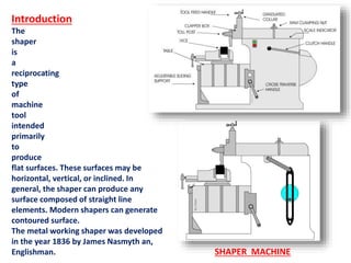
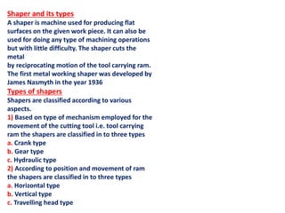
1. A shaper is a machine tool used to produce flat surfaces on workpieces through the reciprocating motion of a toolhead. The first metalworking shaper was developed in 1836.
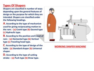
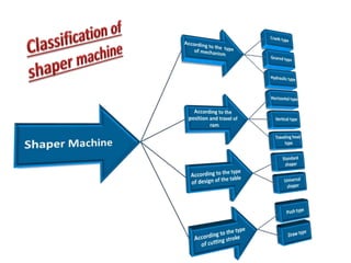
2. Shapers are classified based on the mechanism that provides reciprocation, the position and travel of the ram, the design of the work table, and the type of cutting stroke.
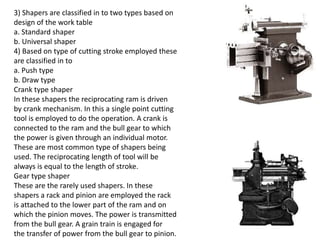
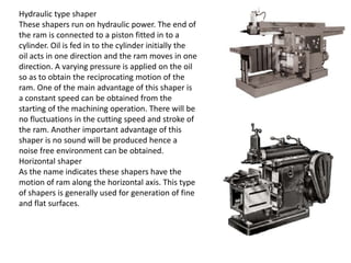
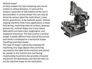
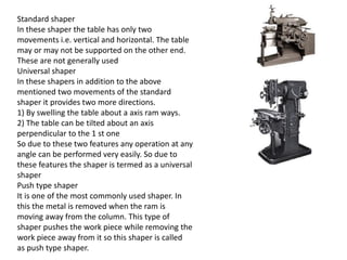
3. Common types include crank-driven shapers, gear-driven shapers, hydraulic shapers, horizontal shapers, vertical shapers, and universal shapers that allow for additional angles of machining.