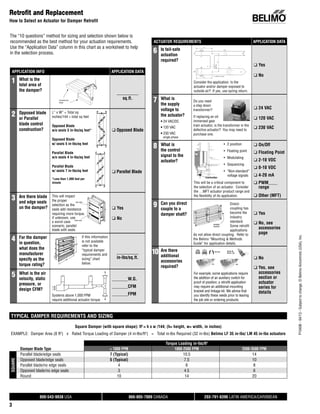
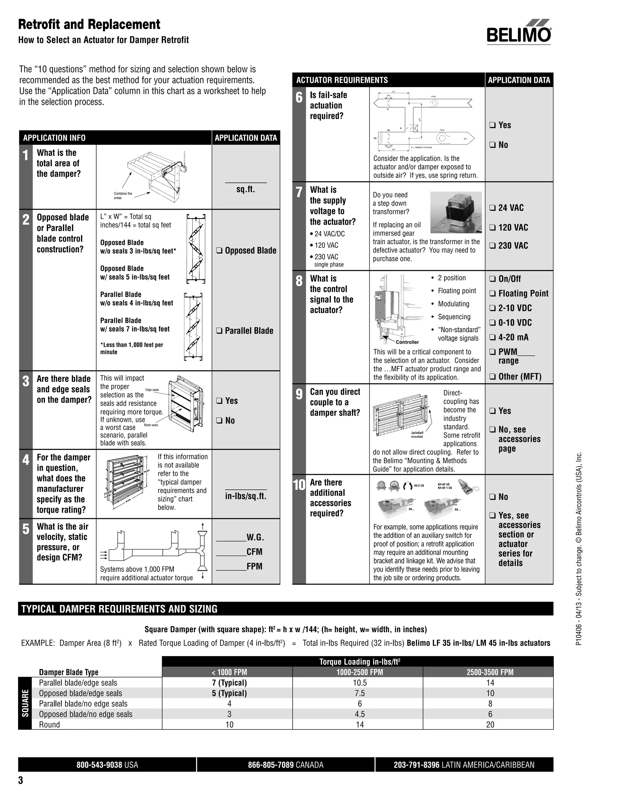
P10406
-
04/13
-
Subject
to
change.
©
Belimo
Aircontrols
(USA),
Inc.
®
800-543-9038 USA 866-805-7089 CANADA 203-791-8396 LATIN AMERICA/CARIBBEAN
3
The “10 questions” method for sizing and selection shown below is
recommended as the best method for your actuation requirements.
Use the “Application Data” column in this chart as a worksheet to help
in the selection process.
Retrofit and Replacement
How to Select an Actuator for Damper Retrofit
APPLICATION INFO APPLICATION DATA
APPLICATION DATA
1 What is the
total area of
the damper?
sq.ft.
2 Opposed blade
or Parallel
blade control
construction?
L” x W” = Total sq
inches/144 = total sq feet
Opposed Blade
w/o seals 3 in-lbs/sq feet*
Opposed Blade
w/ seals 5 in-lbs/sq feet
Parallel Blade
w/o seals 4 in-lbs/sq feet
Parallel Blade
w/ seals 7 in-lbs/sq feet
*Less than 1,000 feet per
minute
❑ Opposed Blade
❑ Parallel Blade
3 Are there blade
and edge seals
on the damper?
This will impact
the proper
selection as the
seals add resistance
requiring more torque.
If unknown, use
a worst case
scenario, parallel
blade with seals.
❑ Yes
❑ No
4 For the damper
in question,
what does the
manufacturer
specify as the
torque rating?
If this information
is not available
refer to the
“typical damper
requirements and
sizing” chart
below.
in-lbs/sq.ft.
5 What is the air
velocity, static
pressure, or
design CFM?
Systems above 1,000 FPM
require additional actuator torque
_______W.G.
_______CFM
_______FPM
ACTUATOR REQUIREMENTS APPLICATION DATA
APPLICATION DATA
6 Is fail-safe
actuation
required?
Consider the application. Is the
actuator and/or damper exposed to
outside air? If yes, use spring return.
❑ Yes
❑ No
7 What is
the supply
voltage to
the actuator?
• 24 VAC/DC
• 120 VAC
• 230 VAC
single phase
Do you need
a step down
transformer?
If replacing an oil
immersed gear
train actuator, is the transformer in the
defective actuator? You may need to
purchase one.
❑ 24 VAC
❑ 120 VAC
❑ 230 VAC
8 What is
the control
signal to the
actuator?
• 2 position
• Floating point
• Modulating
• Sequencing
• “Non-standard”
voltage signals
❑ On/Off
❑ Floating Point
❑ 2-10 VDC
❑ 0-10 VDC
❑ 4-20 mA
❑ PWM____
range
❑ Other (MFT)
This will be a critical component to
the selection of an actuator. Consider
the …MFT actuator product range and
the flexibility of its application.
9 Can you direct
couple to a
damper shaft?
Direct-
coupling has
become the
industry
standard.
Some retrofit
applications
do not allow direct coupling. Refer to
the Belimo “Mounting & Methods
Guide” for application details.
❑ Yes
❑ No, see
accessories
page
10 Are there
additional
accessories
required?
PA… SA…
KH-AF US
KH-AF-1 US
K4-2 US
For example, some applications require
the addition of an auxiliary switch for
proof of position; a retrofit application
may require an additional mounting
bracket and linkage kit. We advise that
you identify these needs prior to leaving
the job site or ordering products.
❑ No
❑ Yes, see
accessories
section or
actuator
series for
details
TYPICAL DAMPER REQUIREMENTS AND SIZING
Square Damper (with square shape): ft2
= h x w /144; (h= height, w= width, in inches)
EXAMPLE: Damper Area (8 ft2
) x Rated Torque Loading of Damper (4 in-lbs/ft2
) = Total in-lbs Required (32 in-lbs) Belimo LF 35 in-lbs/ LM 45 in-lbs actuators
Torque Loading in-lbs/ft2
Damper Blade Type < 1000 FPM 1000-2500 FPM 2500-3500 FPM
SQUARE
Parallel blade/edge seals 7 (Typical) 10.5 14
Opposed blade/edge seals 5 (Typical) 7.5 10
Parallel blade/no edge seals 4 6 8
Opposed blade/no edge seals 3 4.5 6
Round 10 14 20
P10406
-
04/13
-
Subject
to
change.
©
Belimo
Aircontrols
(USA),
Inc.
®
800-543-9038 USA 866-805-7089 CANADA 203-791-8396 LATIN AMERICA/CARIBBEAN
4
CONTROL SIGNAL OVERVIEW
Belimo actuators are compatible with many control inputs and all direct digital control (DDC) systems. There are many signals to select from
with today’s controllers.
On/Off or Open-Close: The actuator is able to drive either to its full
clockwise (CW) position, or to its full counter-clockwise (CCW)
position. The same indication is used for spring return type
actuators. Where the actuator will drive to its full CW position and
spring return to its CCW position. This can also be reversed.
3-point, Tri-State, Floating Point: The actuator has both clockwise
(CW) and counter-clockwise (CCW) control inputs. One drives the
actuator to its CW, the other to its CCW position. If there is no signal
(Null point) on either input the actuator simply stays in its last
position.
Proportional Control: The actuator drives proportional to its control
input and modulates throughout its angle of rotation. This control
type is usually a variation of VDC. Common values are:
0-10 VDC 2-10 VDC
It is common to also have a 0-20/4-20 mA output from a controller.
This can be very easily converted to 0-10 VDC or 2-10 VDC with a
500 Ω resistor.
Pulse Width Modulation (PWM): The actuator drives to a specified
position according to a pulse duration, the “length” of signal. The
pulse can originate from a dry contact closure or a triac sink or
source controller. An example of PWM control:
Time base: 0 to 10 seconds
Output pulse: 5 seconds
Actuator position: 50%
Phasecut: An actuator drives depending on the power result of a
remaining wave. This signal type cuts the amplitude of the wave and
the actuator recognizes this signal as a proportional movement.
Multi-Functional Technology (MFT): This technology was
developed by Belimo for incorporation into our damper and valve
actuators. MFT provides the ability to program certain characteristics
of the actuators. Some of the key characteristics to change are:
CONTROL INPUT
Selectable on/off, VDC, PWM or floating point
MOTION VALUES
Selectable running time adjustment
FEEDBACK
Selectable feedback values
Retrofit and Replacement
How to Select an Actuator
TYPICAL DAMPER REQUIREMENTS AND SIZING EXAMPLE:
APPLICATION REQUIREMENTS SQUARE DAMPER ROUND DAMPER
Damper Length 24"
Damper Width 12"
Damper (Round) 12"
Blade Type Opposed Round
Edge Seals Edge Seals
Design CFM 1800 CFM 700 CFM
Fail-Safe Yes Yes
Supply Voltage 24 Volt 24 Volt
Control Signal 2-10 VDC 2-10 VDC
CALCULATIONS
Damper Area (sq inches) 24" x 12" = 288 in2
πr² =113.04 in2
Damper Area (sq feet)* 288 in2
x 1ft/12 in x 1ft/12 in = 2 ft2
113.04 in2
/ 1ft/12in x 1ft/12in= 0.785 ft2
Velocity 1800 ft3
/min / 2 ft2
= 900 ft/min 700 ft3
/min / .785 ft2
= 892 ft/min
See chart under <1000 FPM (ft/min) See chart under <1000 FPM (ft/min)
Rated Torque Loading (in-lbs/ft2
)** Select 5 in-lbs/ft2
for Opposed Blade/Edge Seals Select 10 in-lbs/ft2
for Round Damper
EXAMPLE EQUATION *Damper Area (sq ft) x **Rated Torque Loading of Damper (in-lbs/ft2
) = Total in-lbs Required
2 ft2
x 5 in-lbs/ft2
= 10 in-lbs
Belimo LF24-SR US @ 35 in-lbs
0.785 ft2
x 10 in-lbs/ft2
= 7.85 in-lbs
Belimo LF24-SR US @ 35 in-lbs

How to size_a_damper_actuator (1)

  • 1.
    P10406 - 04/13 - Subject to change. © Belimo Aircontrols (USA), Inc. ® 800-543-9038 USA 866-805-7089CANADA 203-791-8396 LATIN AMERICA/CARIBBEAN 3 The “10 questions” method for sizing and selection shown below is recommended as the best method for your actuation requirements. Use the “Application Data” column in this chart as a worksheet to help in the selection process. Retrofit and Replacement How to Select an Actuator for Damper Retrofit APPLICATION INFO APPLICATION DATA APPLICATION DATA 1 What is the total area of the damper? sq.ft. 2 Opposed blade or Parallel blade control construction? L” x W” = Total sq inches/144 = total sq feet Opposed Blade w/o seals 3 in-lbs/sq feet* Opposed Blade w/ seals 5 in-lbs/sq feet Parallel Blade w/o seals 4 in-lbs/sq feet Parallel Blade w/ seals 7 in-lbs/sq feet *Less than 1,000 feet per minute ❑ Opposed Blade ❑ Parallel Blade 3 Are there blade and edge seals on the damper? This will impact the proper selection as the seals add resistance requiring more torque. If unknown, use a worst case scenario, parallel blade with seals. ❑ Yes ❑ No 4 For the damper in question, what does the manufacturer specify as the torque rating? If this information is not available refer to the “typical damper requirements and sizing” chart below. in-lbs/sq.ft. 5 What is the air velocity, static pressure, or design CFM? Systems above 1,000 FPM require additional actuator torque _______W.G. _______CFM _______FPM ACTUATOR REQUIREMENTS APPLICATION DATA APPLICATION DATA 6 Is fail-safe actuation required? Consider the application. Is the actuator and/or damper exposed to outside air? If yes, use spring return. ❑ Yes ❑ No 7 What is the supply voltage to the actuator? • 24 VAC/DC • 120 VAC • 230 VAC single phase Do you need a step down transformer? If replacing an oil immersed gear train actuator, is the transformer in the defective actuator? You may need to purchase one. ❑ 24 VAC ❑ 120 VAC ❑ 230 VAC 8 What is the control signal to the actuator? • 2 position • Floating point • Modulating • Sequencing • “Non-standard” voltage signals ❑ On/Off ❑ Floating Point ❑ 2-10 VDC ❑ 0-10 VDC ❑ 4-20 mA ❑ PWM____ range ❑ Other (MFT) This will be a critical component to the selection of an actuator. Consider the …MFT actuator product range and the flexibility of its application. 9 Can you direct couple to a damper shaft? Direct- coupling has become the industry standard. Some retrofit applications do not allow direct coupling. Refer to the Belimo “Mounting & Methods Guide” for application details. ❑ Yes ❑ No, see accessories page 10 Are there additional accessories required? PA… SA… KH-AF US KH-AF-1 US K4-2 US For example, some applications require the addition of an auxiliary switch for proof of position; a retrofit application may require an additional mounting bracket and linkage kit. We advise that you identify these needs prior to leaving the job site or ordering products. ❑ No ❑ Yes, see accessories section or actuator series for details TYPICAL DAMPER REQUIREMENTS AND SIZING Square Damper (with square shape): ft2 = h x w /144; (h= height, w= width, in inches) EXAMPLE: Damper Area (8 ft2 ) x Rated Torque Loading of Damper (4 in-lbs/ft2 ) = Total in-lbs Required (32 in-lbs) Belimo LF 35 in-lbs/ LM 45 in-lbs actuators Torque Loading in-lbs/ft2 Damper Blade Type < 1000 FPM 1000-2500 FPM 2500-3500 FPM SQUARE Parallel blade/edge seals 7 (Typical) 10.5 14 Opposed blade/edge seals 5 (Typical) 7.5 10 Parallel blade/no edge seals 4 6 8 Opposed blade/no edge seals 3 4.5 6 Round 10 14 20
  • 2.
    P10406 - 04/13 - Subject to change. © Belimo Aircontrols (USA), Inc. ® 800-543-9038 USA 866-805-7089CANADA 203-791-8396 LATIN AMERICA/CARIBBEAN 4 CONTROL SIGNAL OVERVIEW Belimo actuators are compatible with many control inputs and all direct digital control (DDC) systems. There are many signals to select from with today’s controllers. On/Off or Open-Close: The actuator is able to drive either to its full clockwise (CW) position, or to its full counter-clockwise (CCW) position. The same indication is used for spring return type actuators. Where the actuator will drive to its full CW position and spring return to its CCW position. This can also be reversed. 3-point, Tri-State, Floating Point: The actuator has both clockwise (CW) and counter-clockwise (CCW) control inputs. One drives the actuator to its CW, the other to its CCW position. If there is no signal (Null point) on either input the actuator simply stays in its last position. Proportional Control: The actuator drives proportional to its control input and modulates throughout its angle of rotation. This control type is usually a variation of VDC. Common values are: 0-10 VDC 2-10 VDC It is common to also have a 0-20/4-20 mA output from a controller. This can be very easily converted to 0-10 VDC or 2-10 VDC with a 500 Ω resistor. Pulse Width Modulation (PWM): The actuator drives to a specified position according to a pulse duration, the “length” of signal. The pulse can originate from a dry contact closure or a triac sink or source controller. An example of PWM control: Time base: 0 to 10 seconds Output pulse: 5 seconds Actuator position: 50% Phasecut: An actuator drives depending on the power result of a remaining wave. This signal type cuts the amplitude of the wave and the actuator recognizes this signal as a proportional movement. Multi-Functional Technology (MFT): This technology was developed by Belimo for incorporation into our damper and valve actuators. MFT provides the ability to program certain characteristics of the actuators. Some of the key characteristics to change are: CONTROL INPUT Selectable on/off, VDC, PWM or floating point MOTION VALUES Selectable running time adjustment FEEDBACK Selectable feedback values Retrofit and Replacement How to Select an Actuator TYPICAL DAMPER REQUIREMENTS AND SIZING EXAMPLE: APPLICATION REQUIREMENTS SQUARE DAMPER ROUND DAMPER Damper Length 24" Damper Width 12" Damper (Round) 12" Blade Type Opposed Round Edge Seals Edge Seals Design CFM 1800 CFM 700 CFM Fail-Safe Yes Yes Supply Voltage 24 Volt 24 Volt Control Signal 2-10 VDC 2-10 VDC CALCULATIONS Damper Area (sq inches) 24" x 12" = 288 in2 πr² =113.04 in2 Damper Area (sq feet)* 288 in2 x 1ft/12 in x 1ft/12 in = 2 ft2 113.04 in2 / 1ft/12in x 1ft/12in= 0.785 ft2 Velocity 1800 ft3 /min / 2 ft2 = 900 ft/min 700 ft3 /min / .785 ft2 = 892 ft/min See chart under <1000 FPM (ft/min) See chart under <1000 FPM (ft/min) Rated Torque Loading (in-lbs/ft2 )** Select 5 in-lbs/ft2 for Opposed Blade/Edge Seals Select 10 in-lbs/ft2 for Round Damper EXAMPLE EQUATION *Damper Area (sq ft) x **Rated Torque Loading of Damper (in-lbs/ft2 ) = Total in-lbs Required 2 ft2 x 5 in-lbs/ft2 = 10 in-lbs Belimo LF24-SR US @ 35 in-lbs 0.785 ft2 x 10 in-lbs/ft2 = 7.85 in-lbs Belimo LF24-SR US @ 35 in-lbs