Download to read offline
![First start-up
Plant shut down
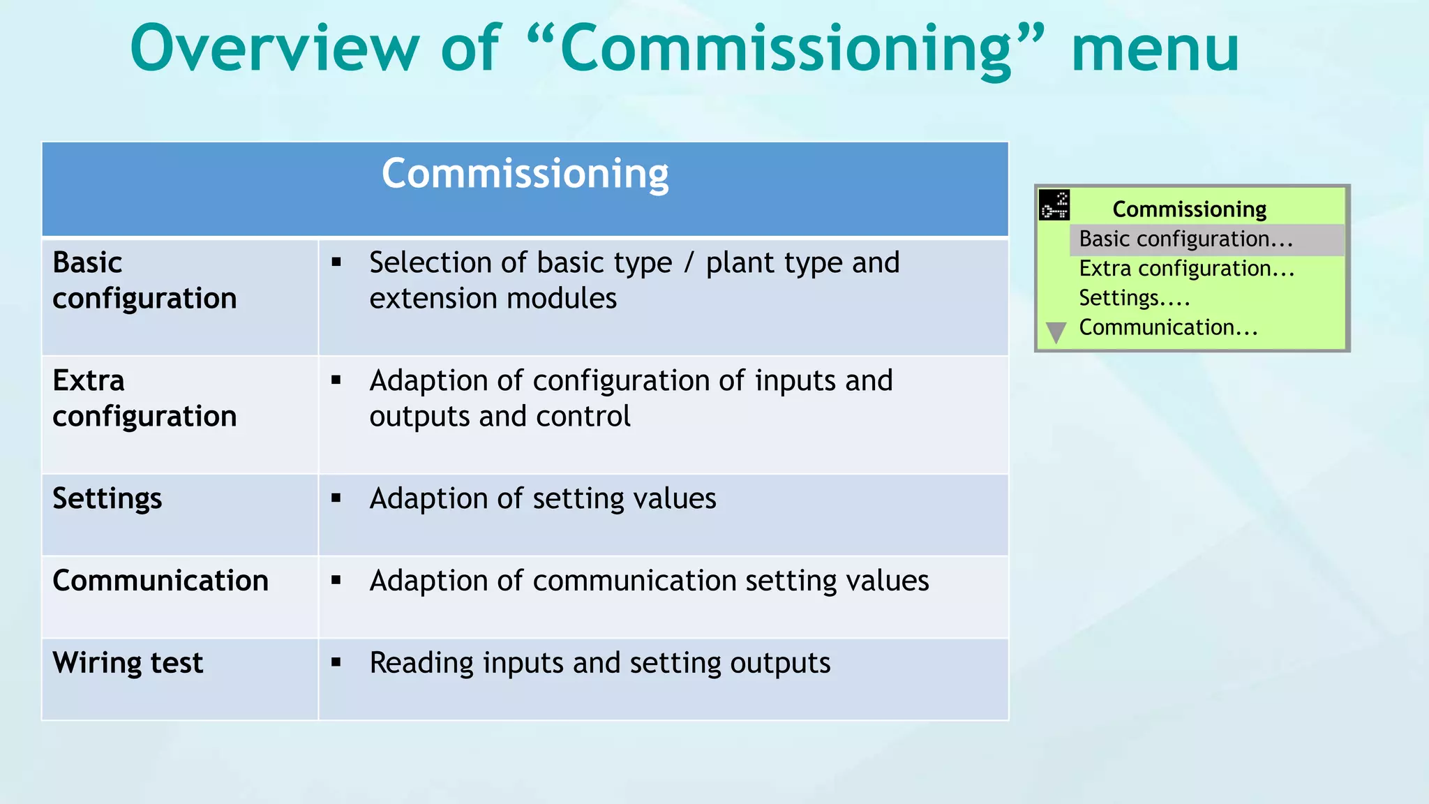
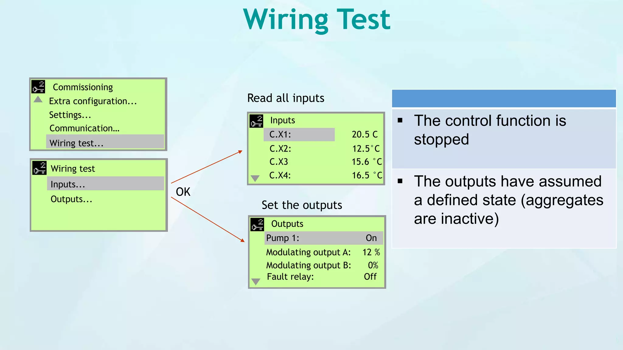
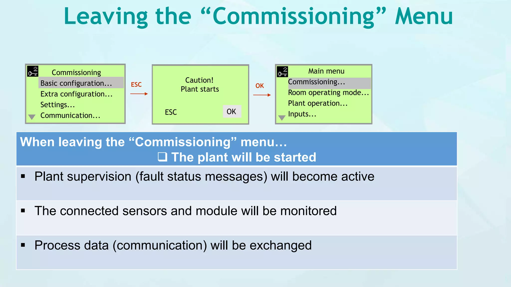
Commissioning
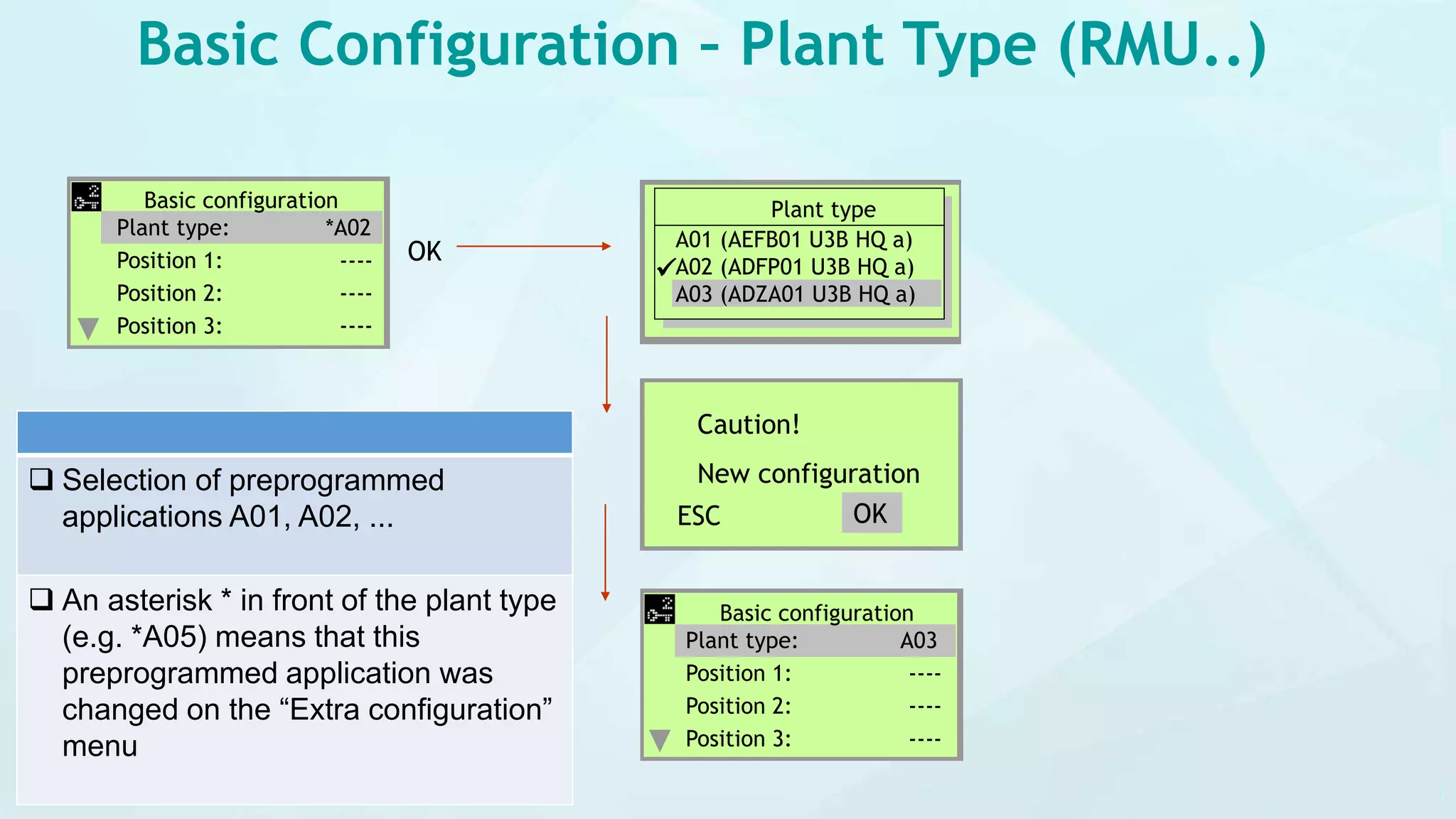
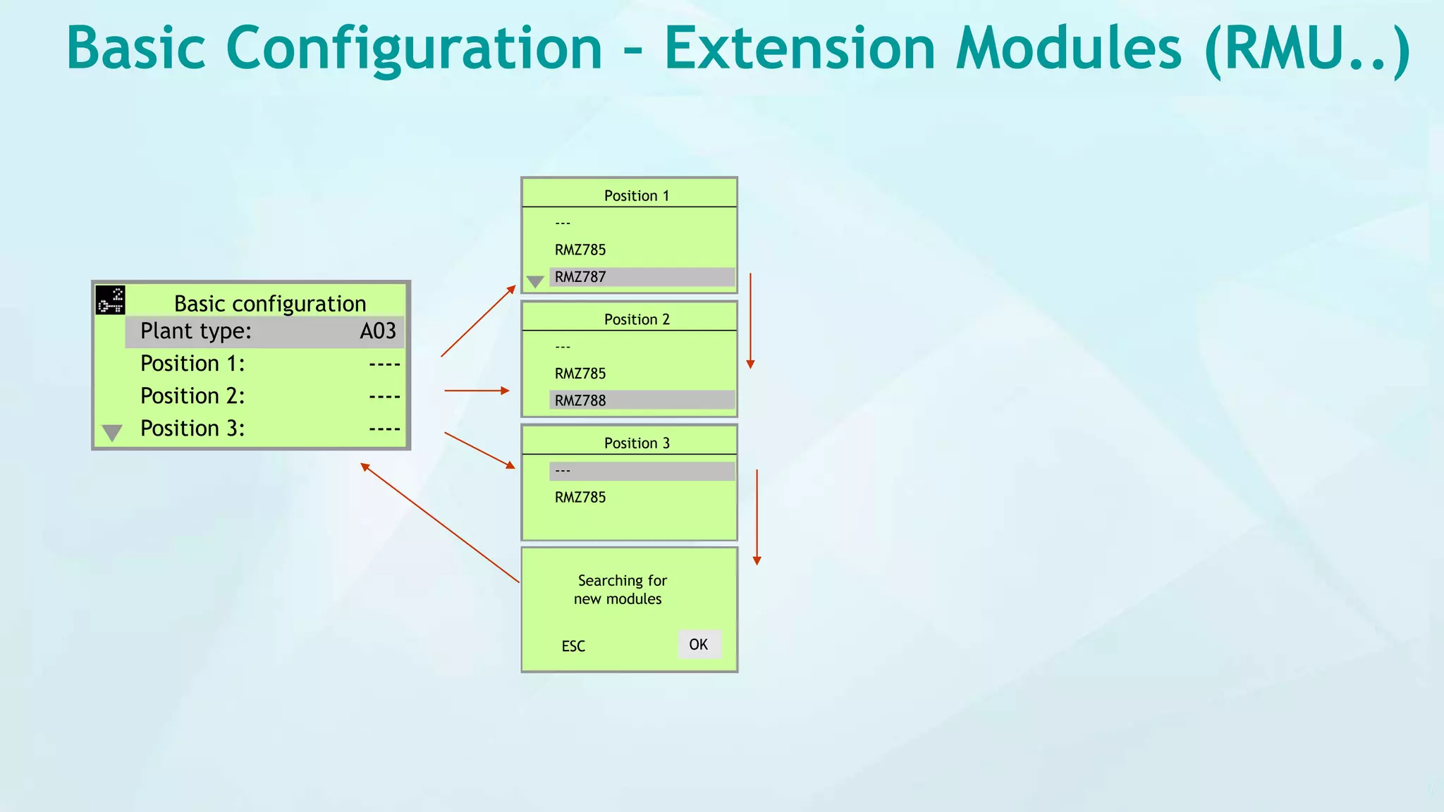
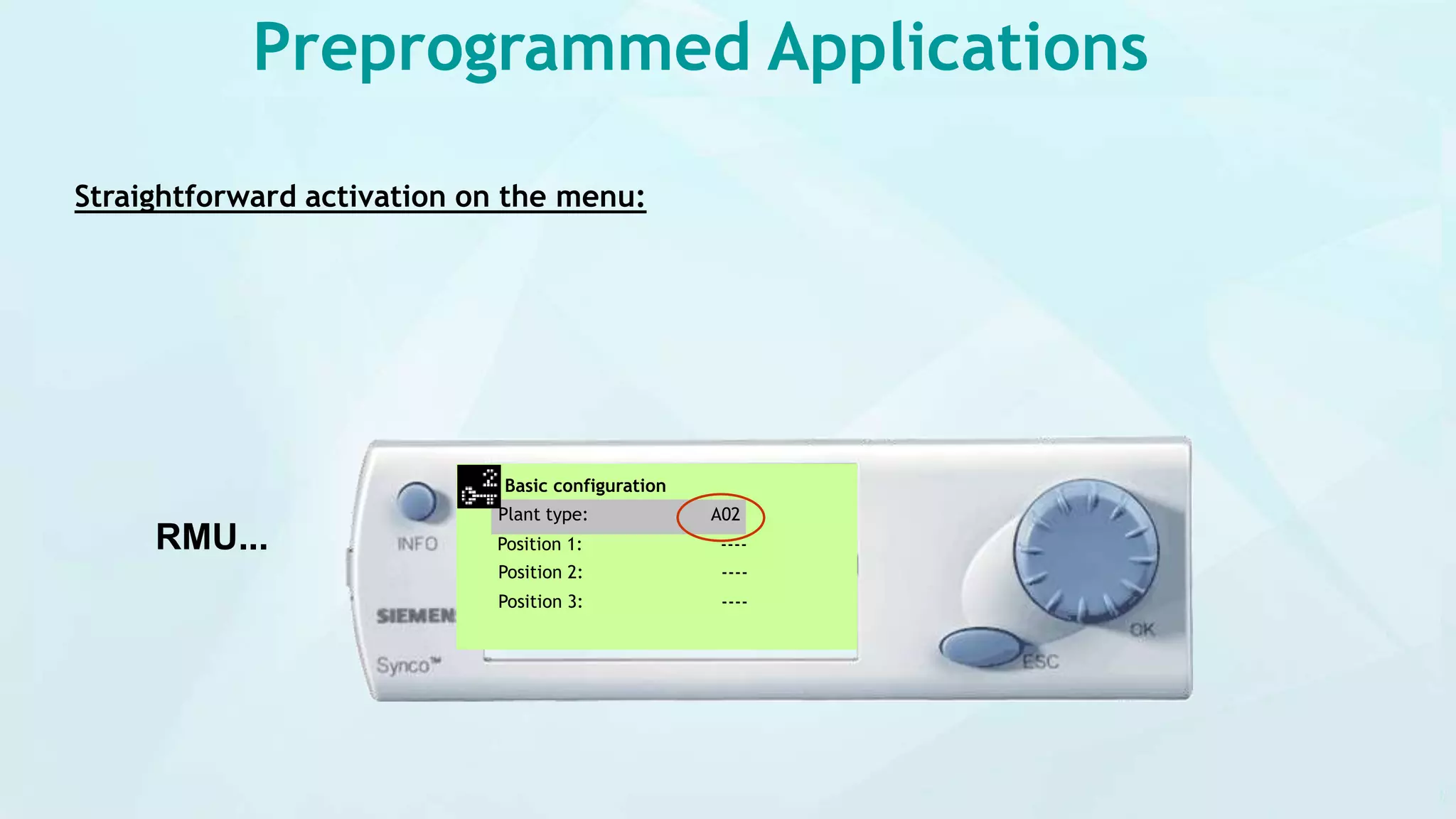
Basic configuration...
Extra configuration...
Settings....
Communication...
Plant in normal mode
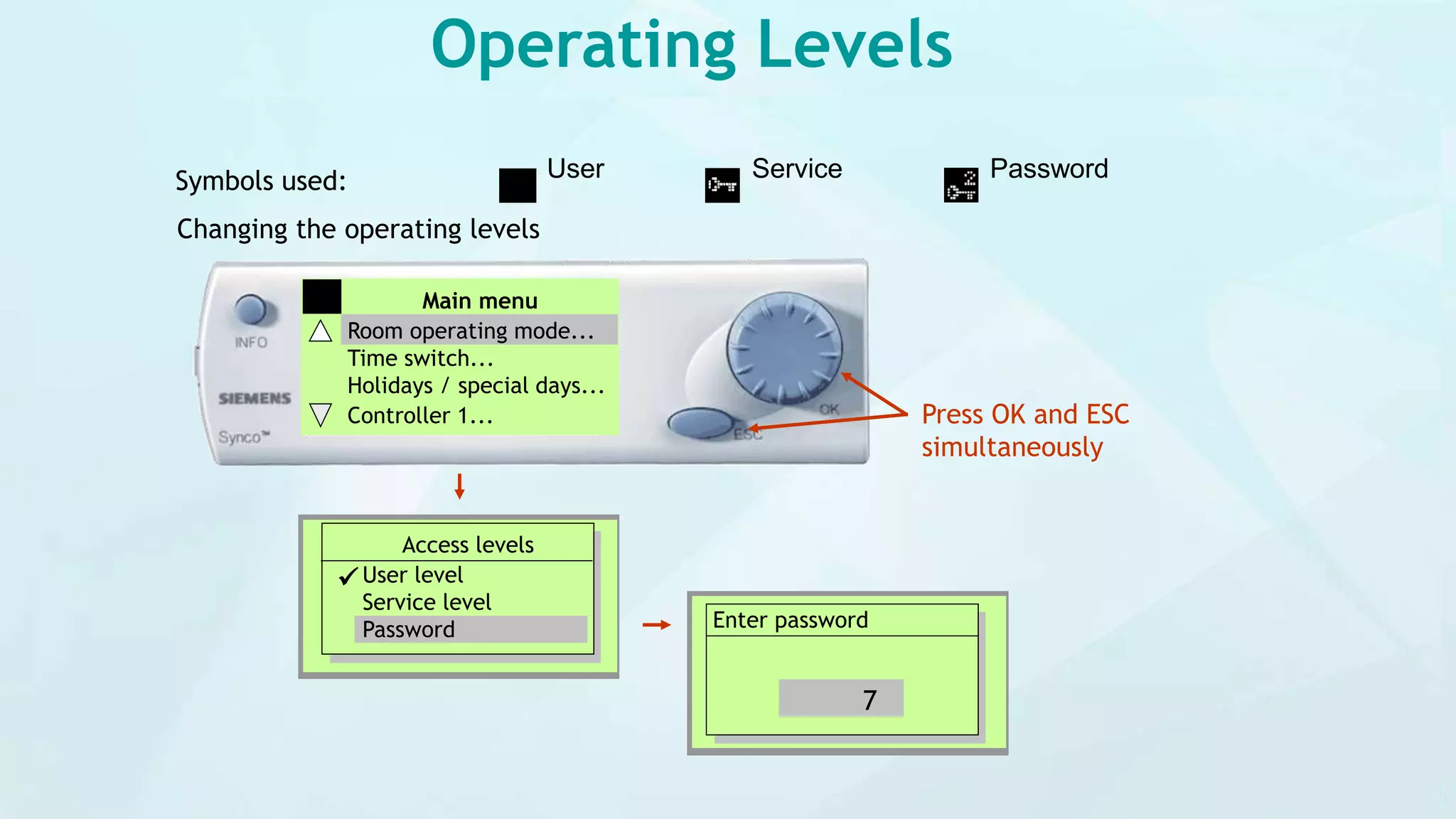
Main menu
Commissioning...
Room operating mode...
Plant operation...
Inputs...
OK
Plant stops
ESC
Plant starts
First startup
Entry commissioning
Date
19.08
[Day.Month]
Enter Time
and Date
Language
English
Deutsch
Italiano](https://image.slidesharecdn.com/syncotm700controlleroperationandcommissioningpart-1-200711055726/75/Synco-tm-700-controller-operation-and-commissioning-part-1-3-2048.jpg)
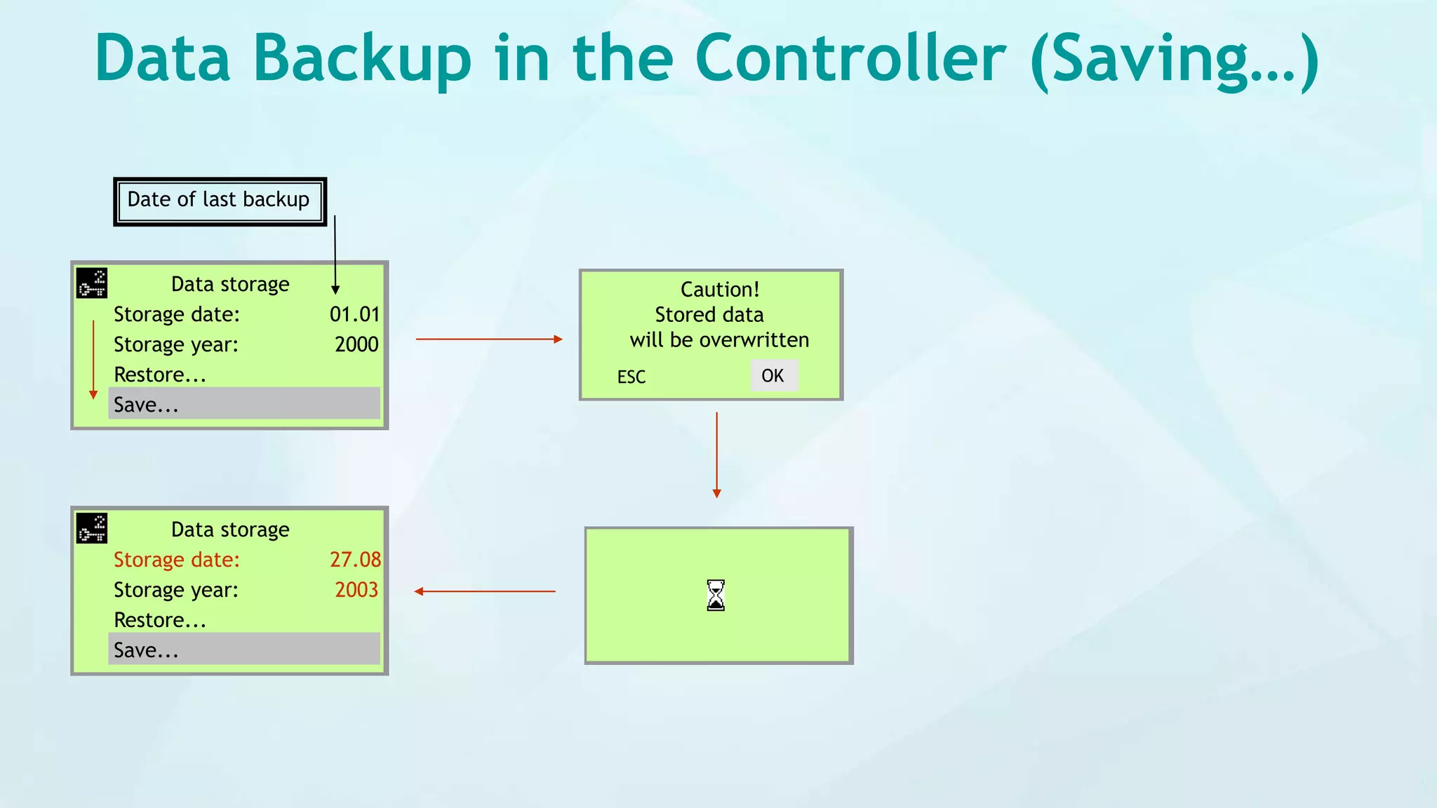
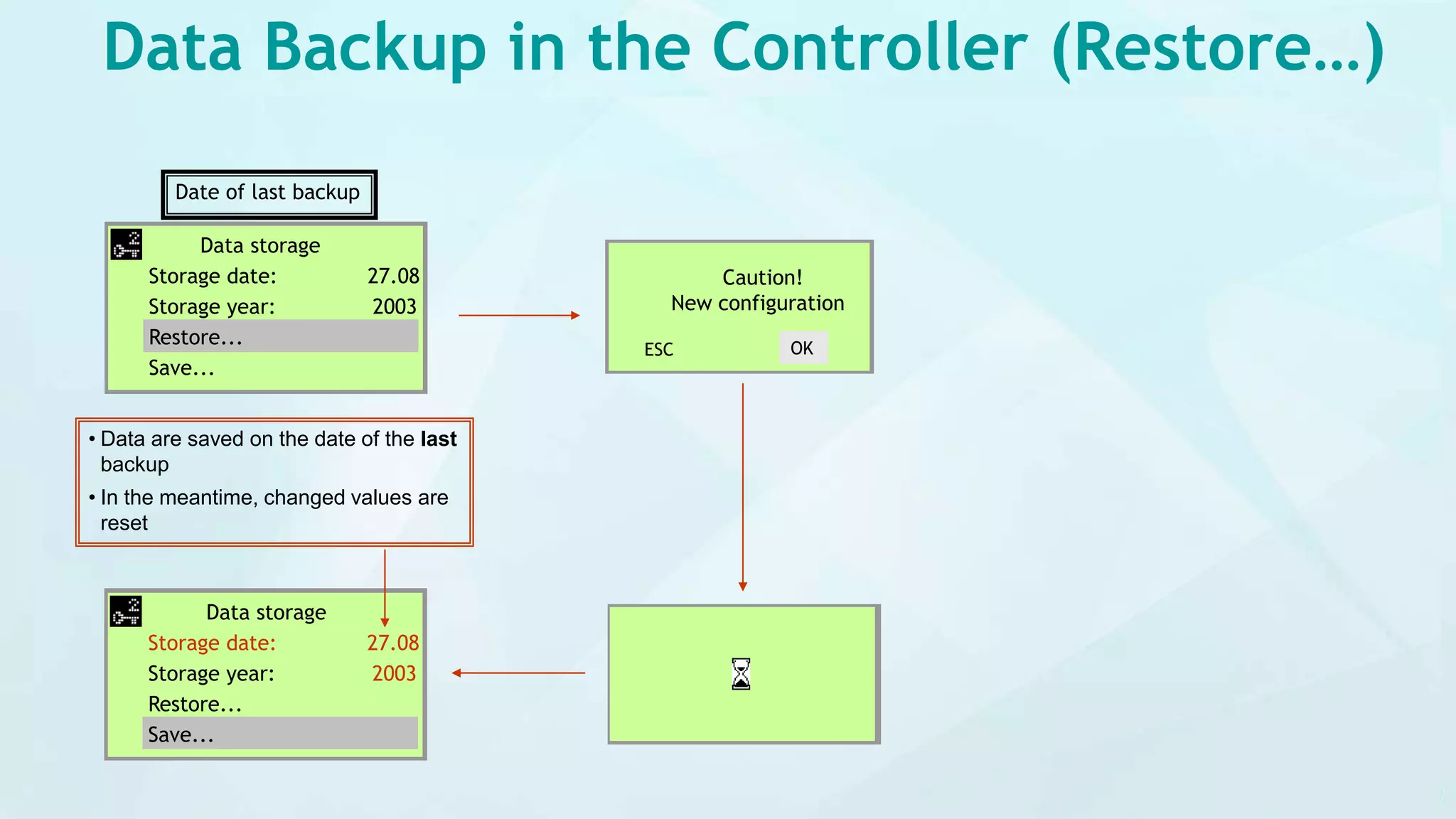
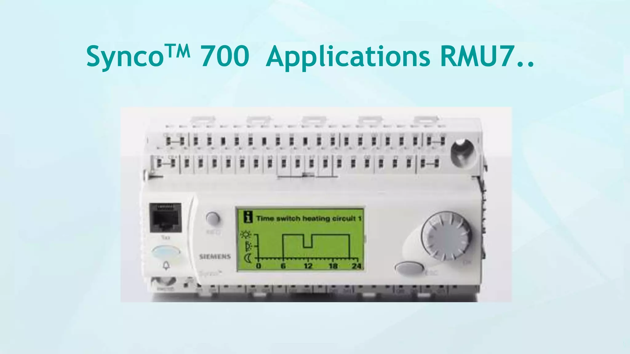
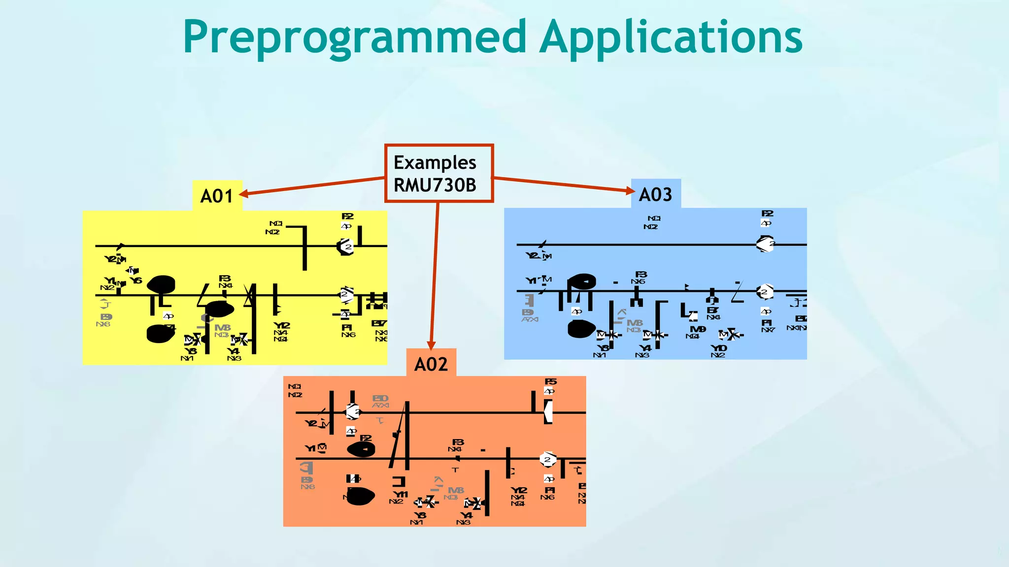
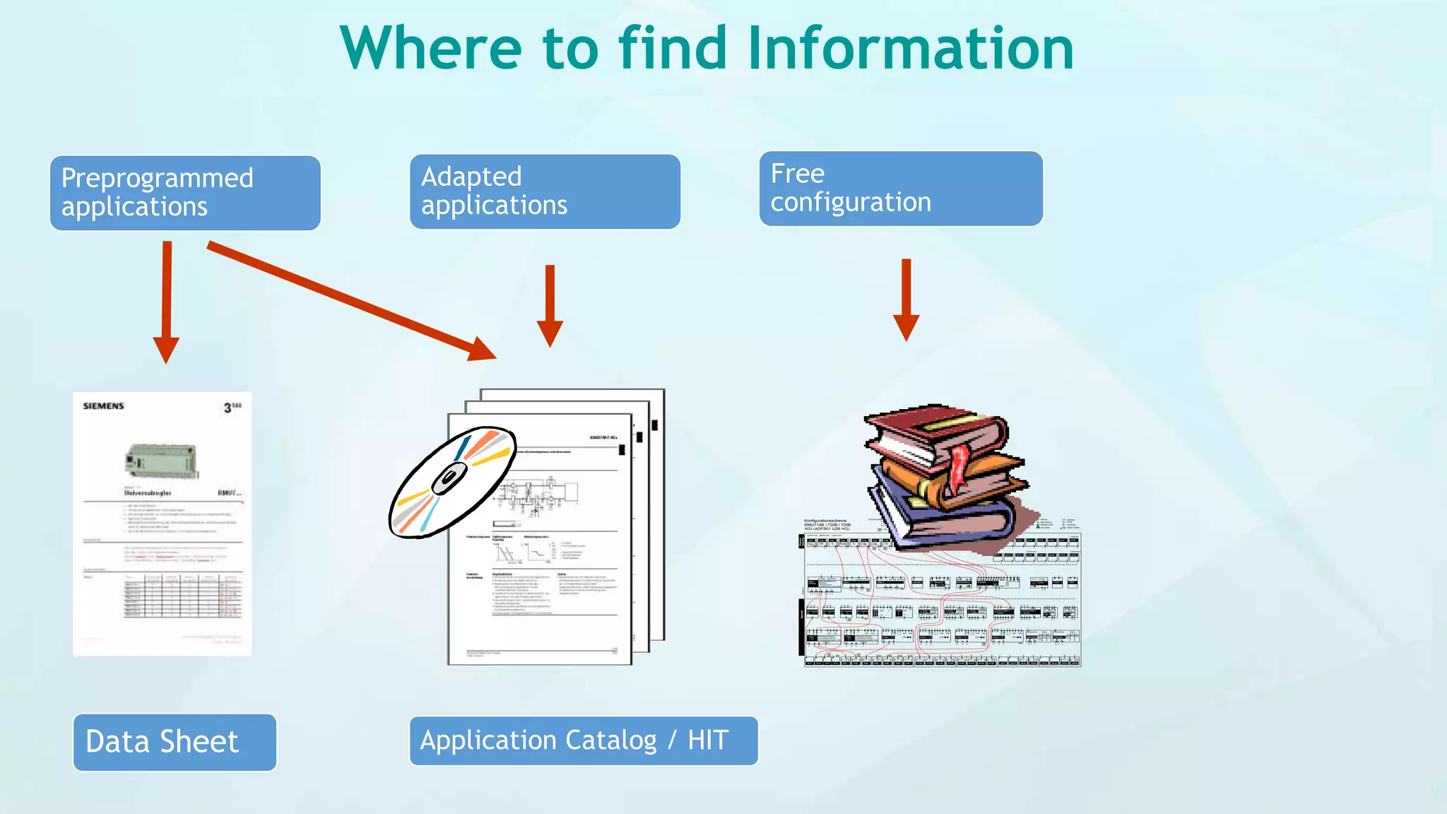
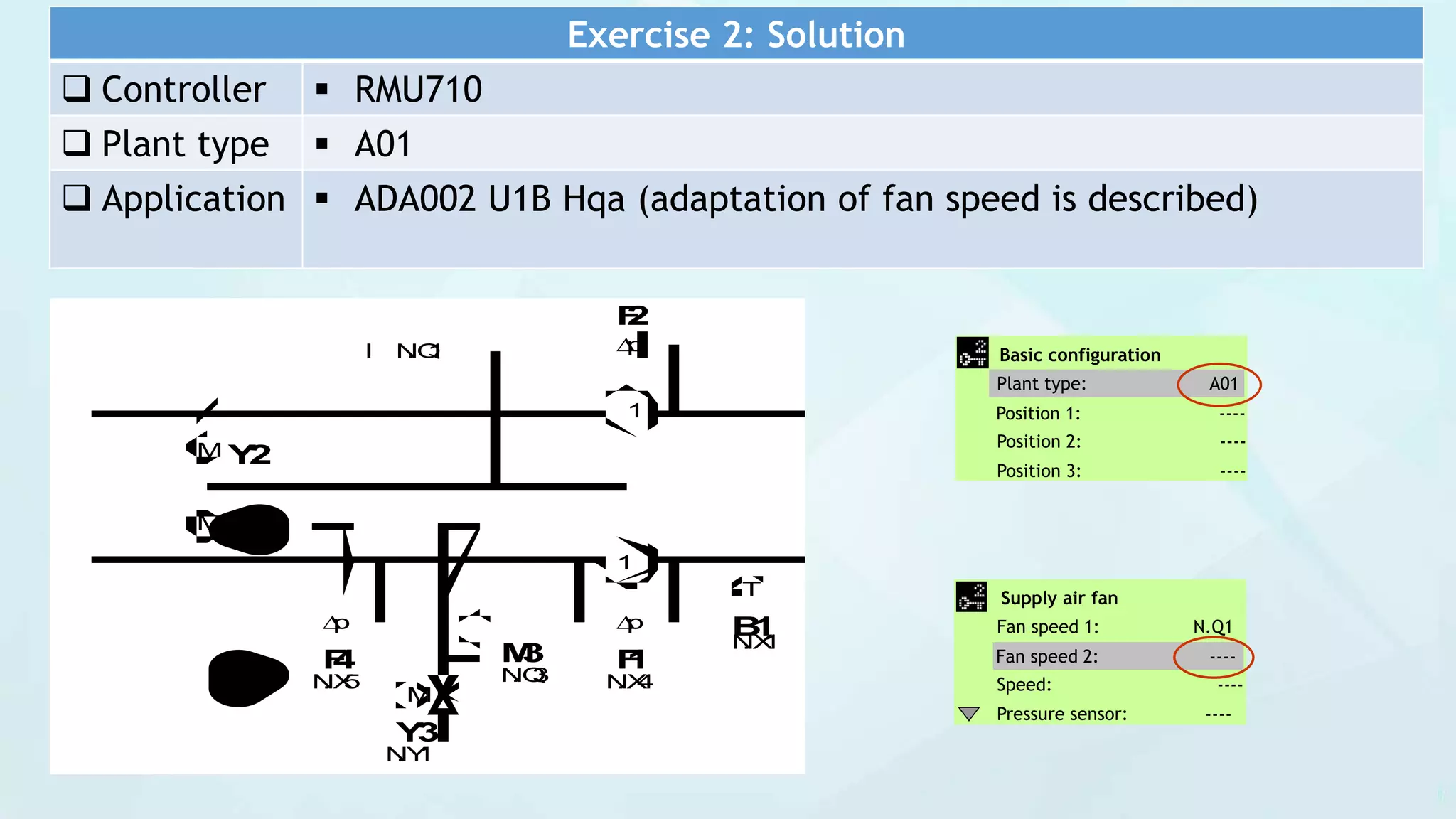

The document provides an operational and commissioning guide for the Siemens Syncotm 700 controller, detailing processes such as plant setup, communication configuration, and monitoring settings. It includes instructions for basic and extra configurations, language selection, input/output settings, and data backup procedures. The guide also features diagrams and a catalog of preprogrammed applications for effective commissioning and operation.


