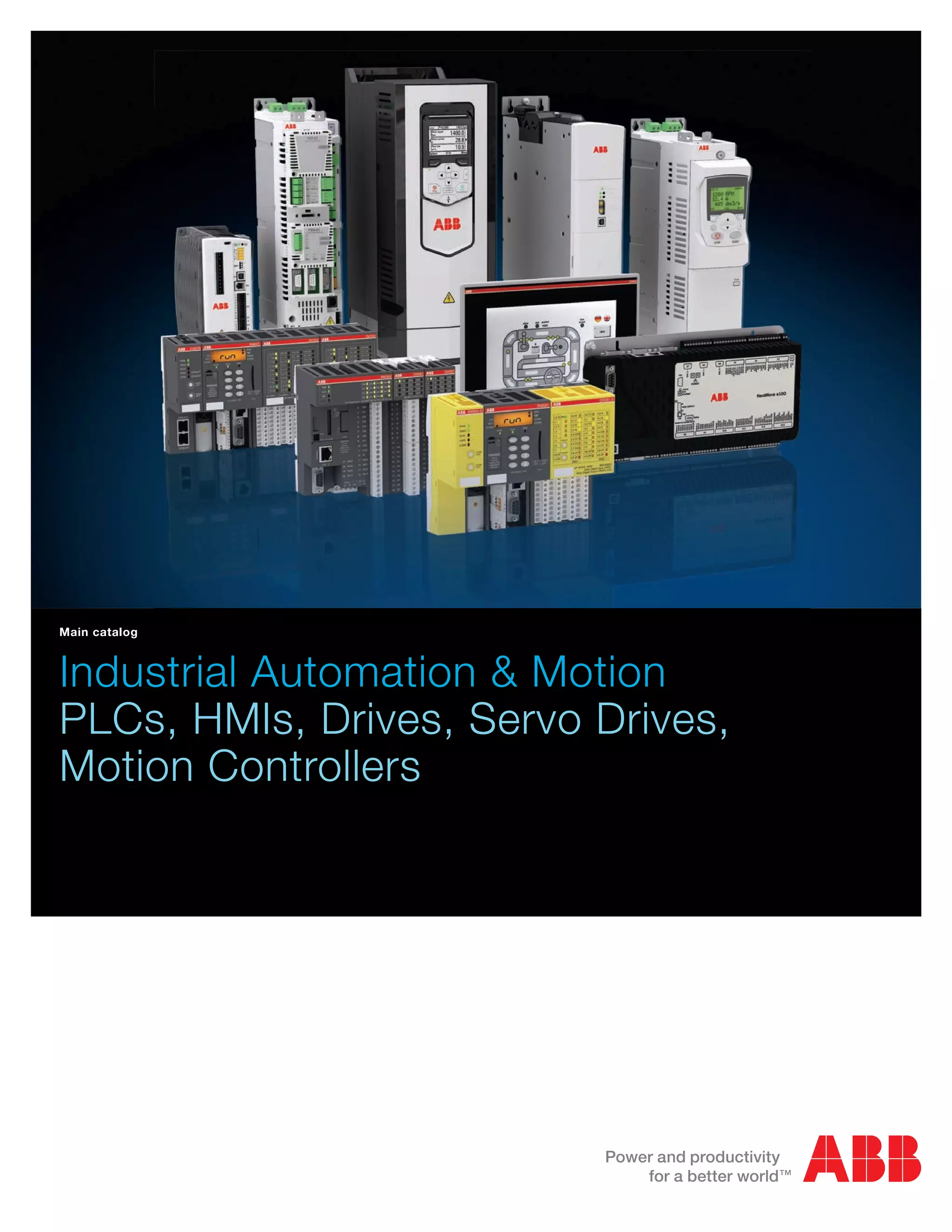
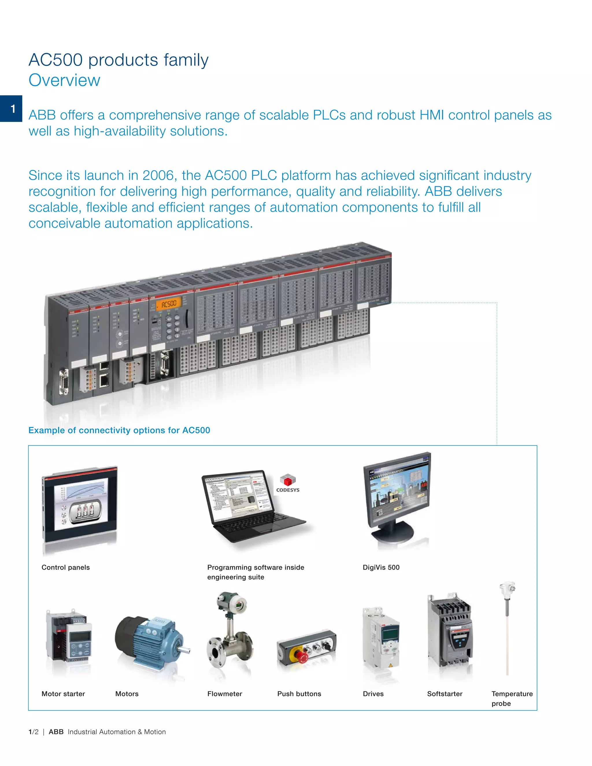
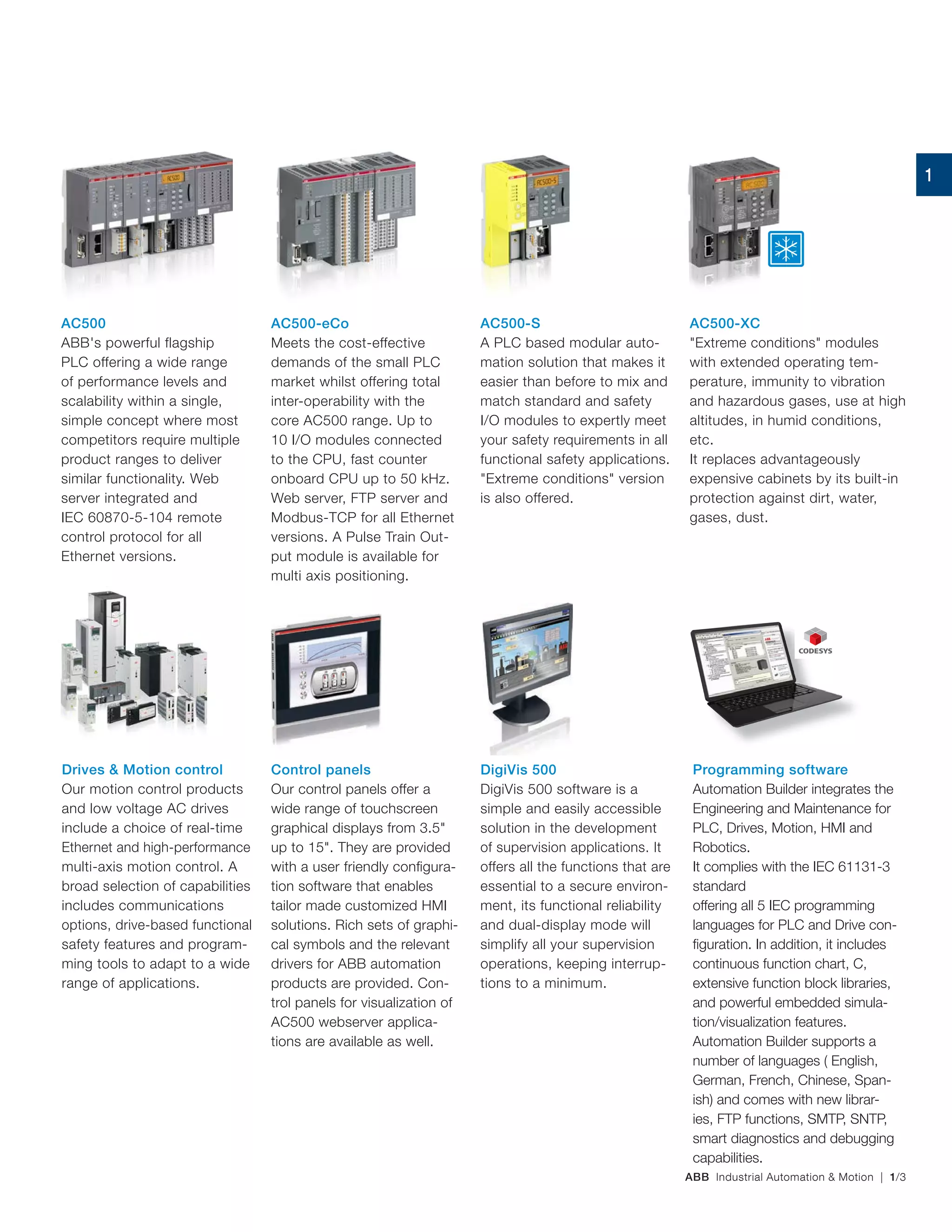
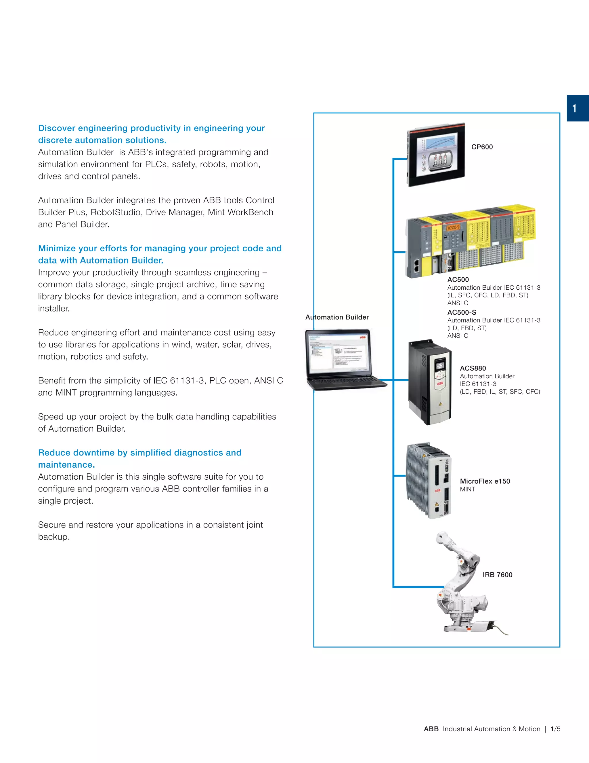
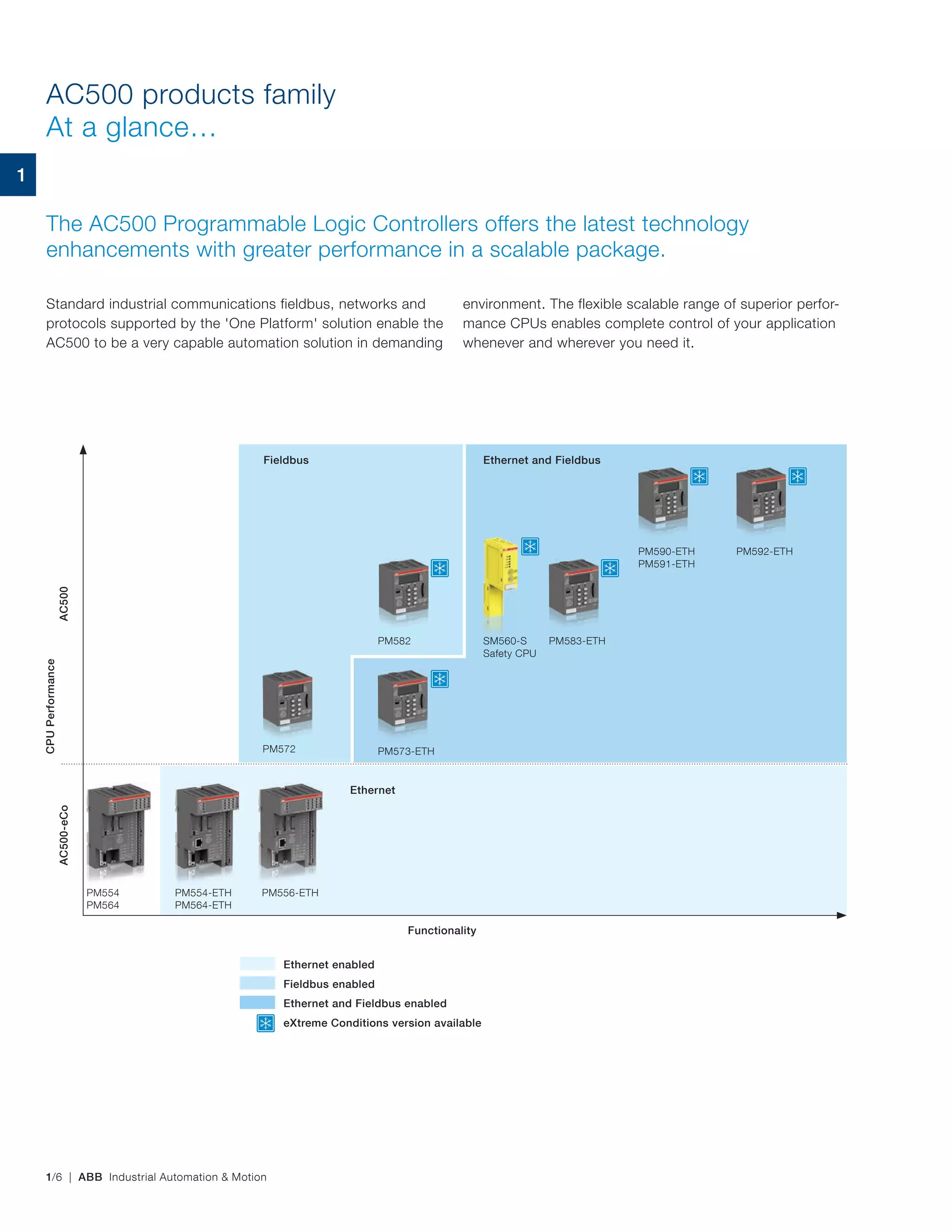
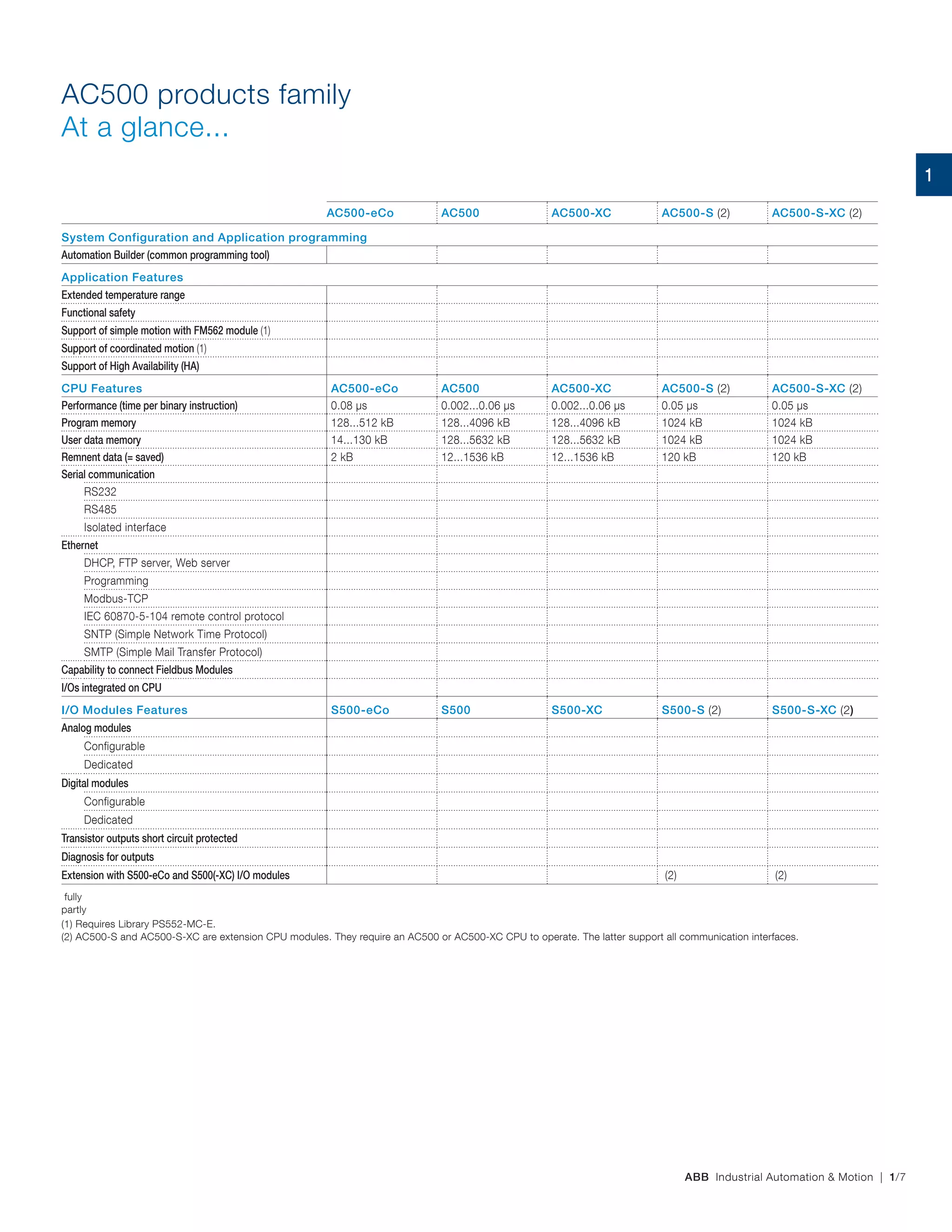
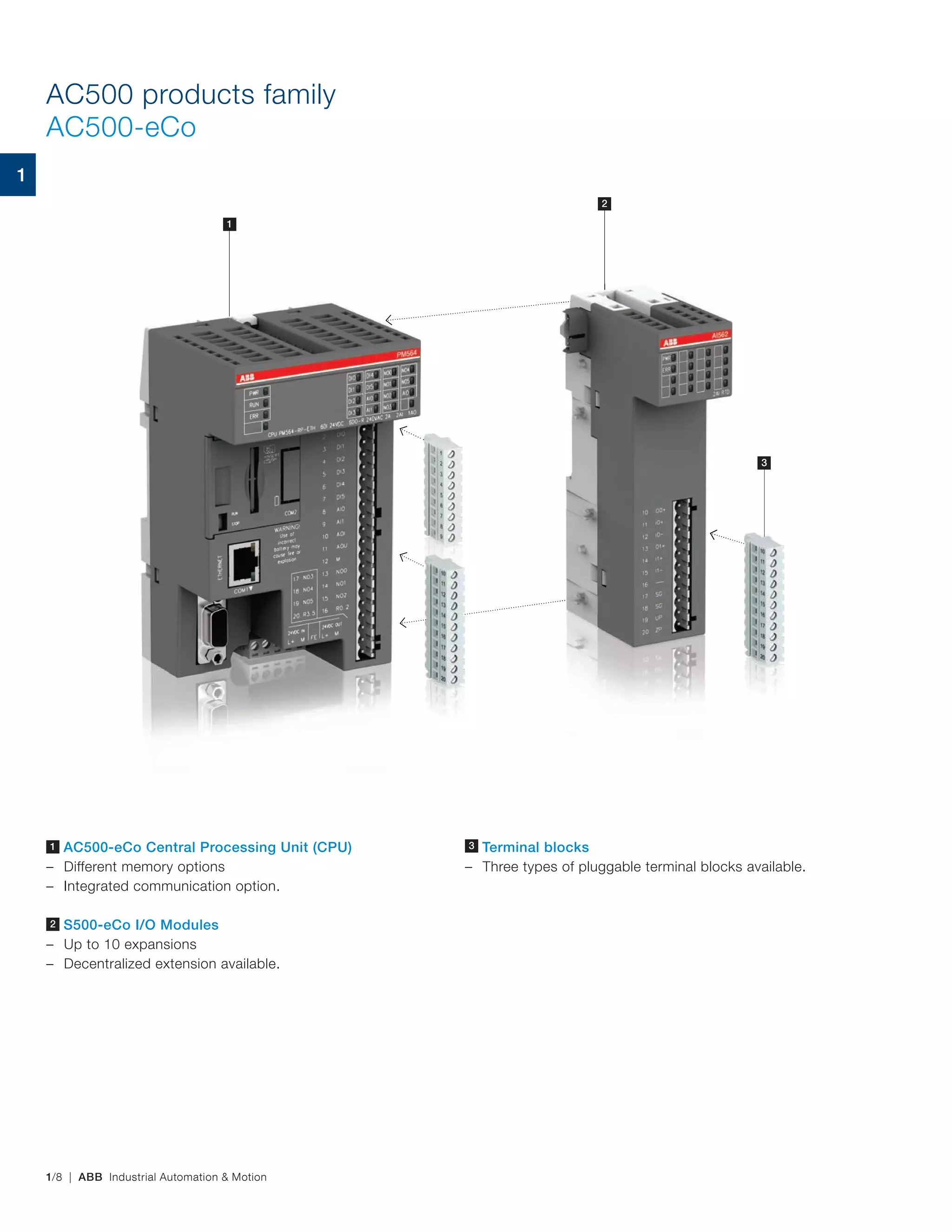
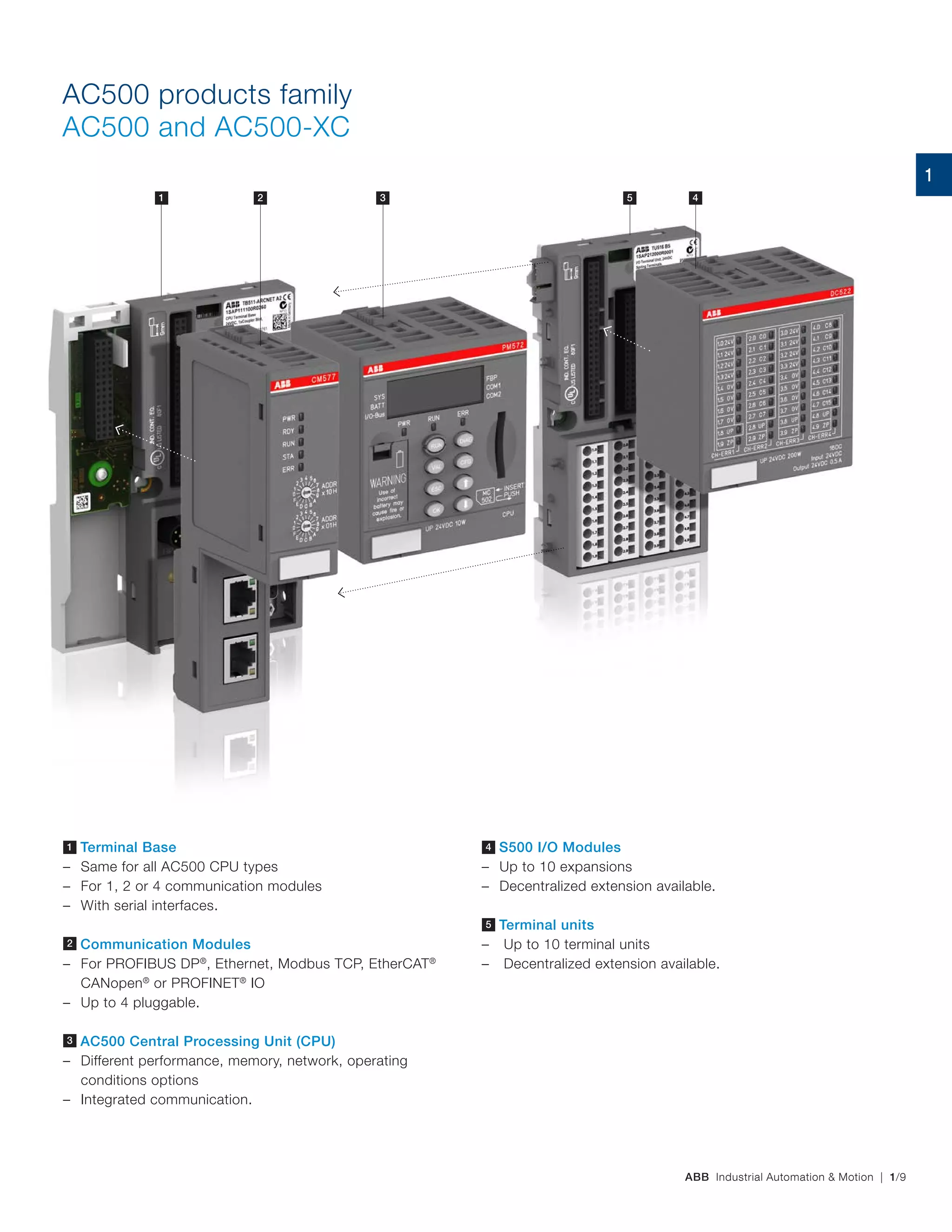
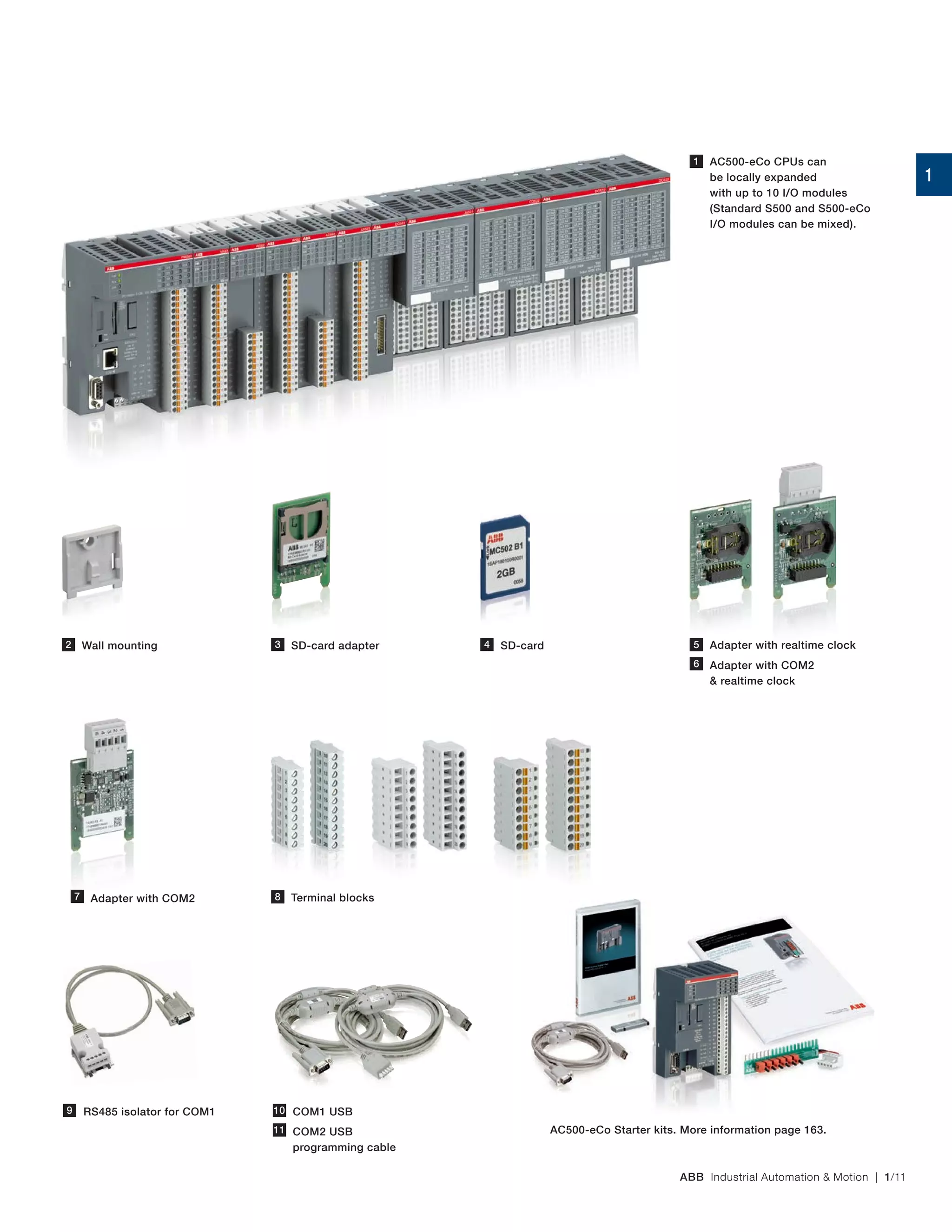
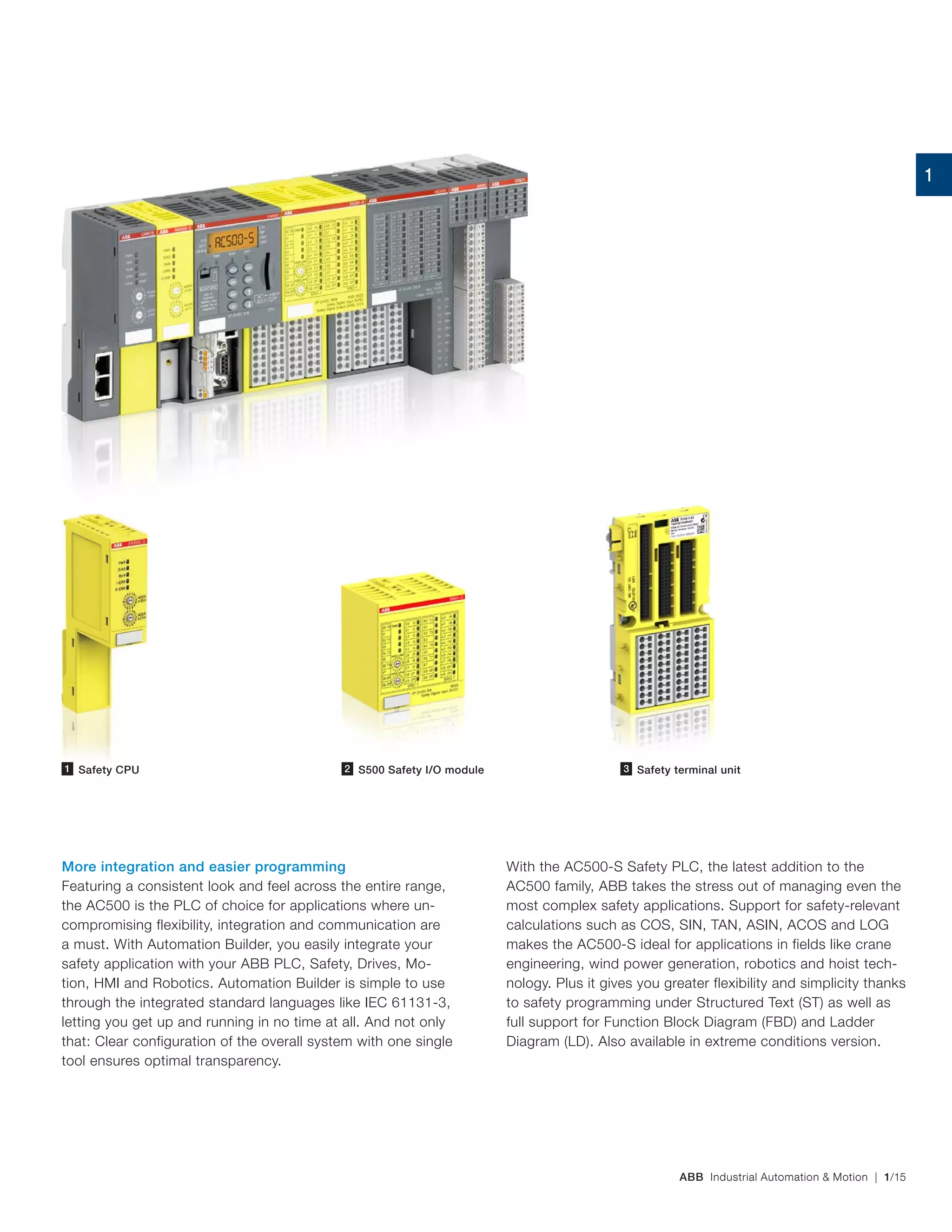
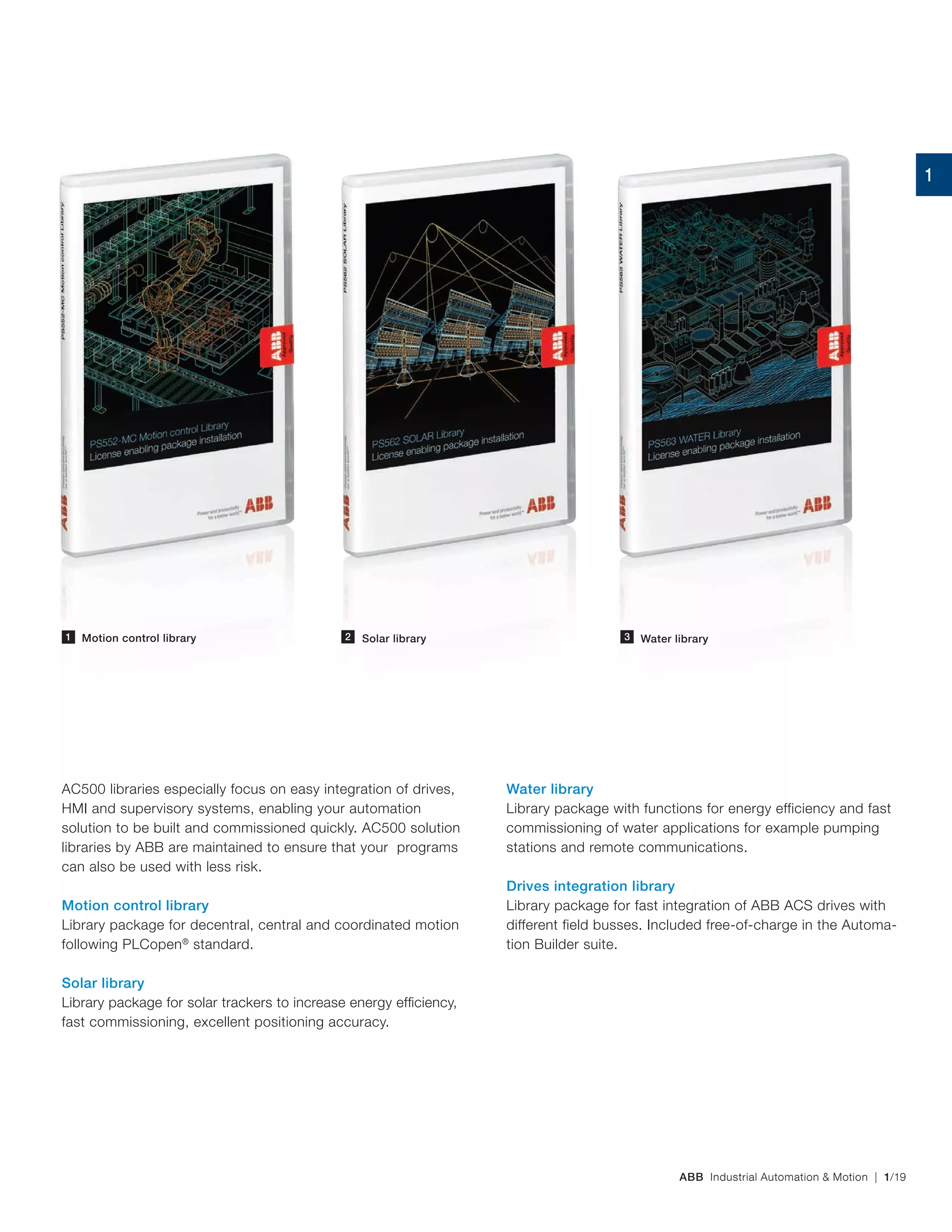
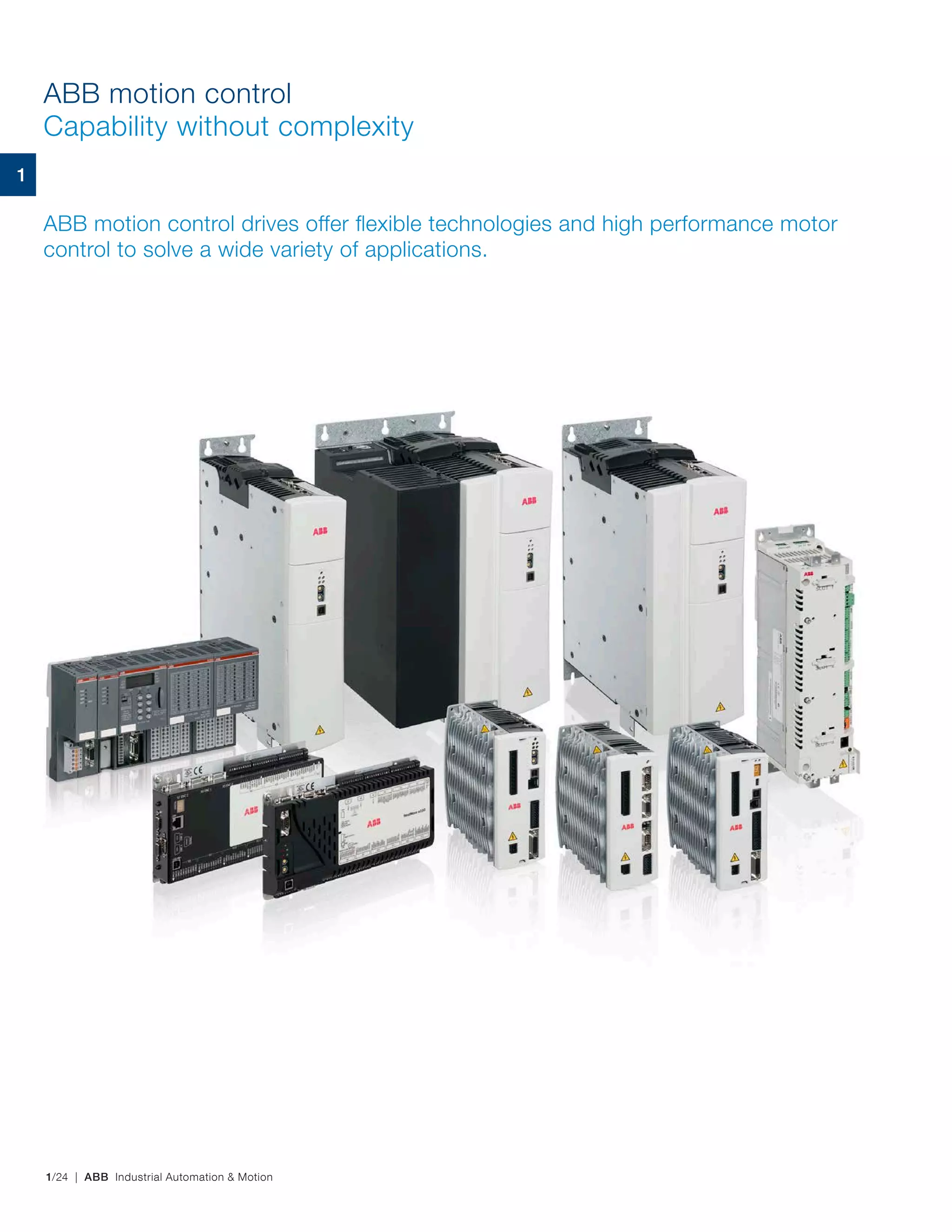
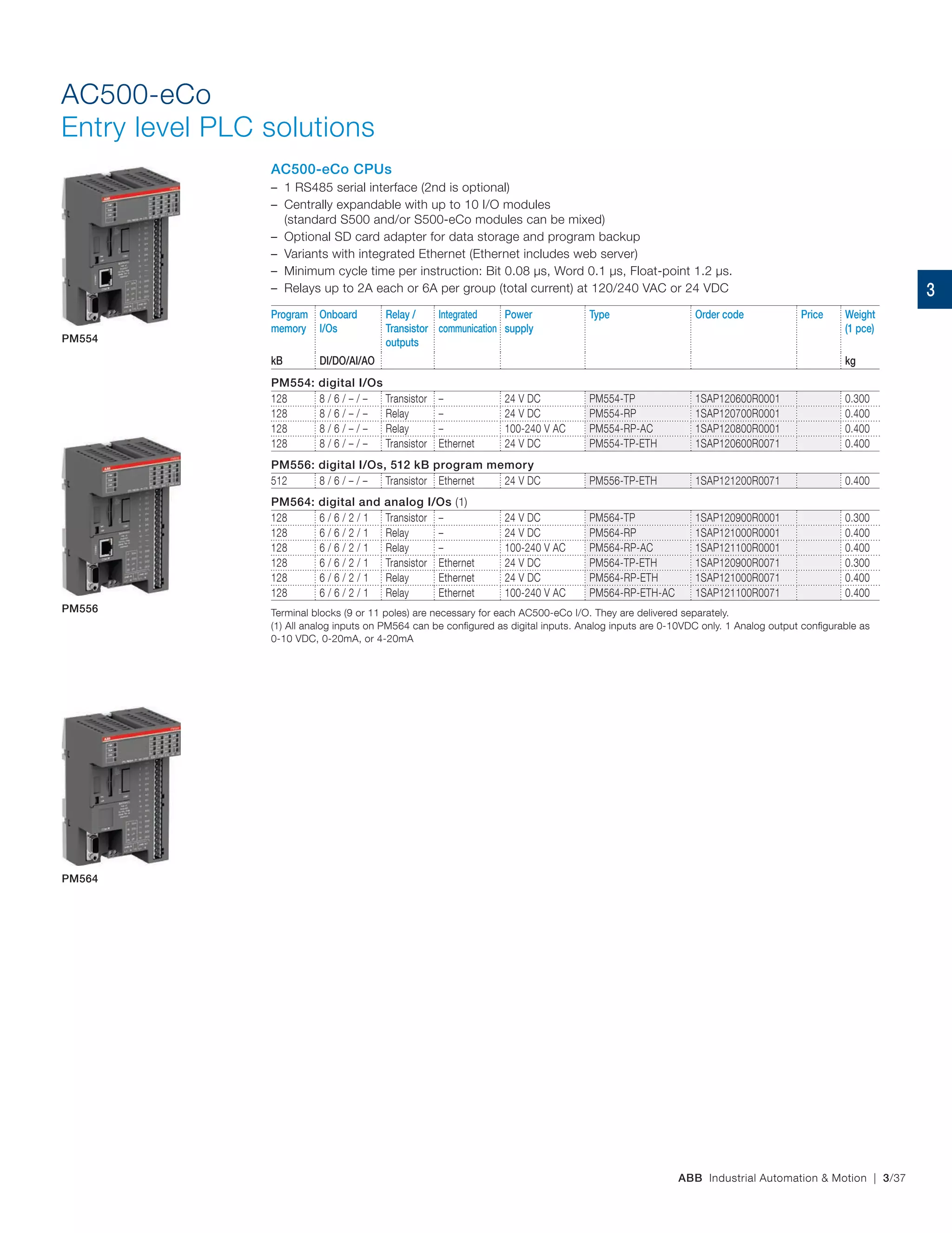
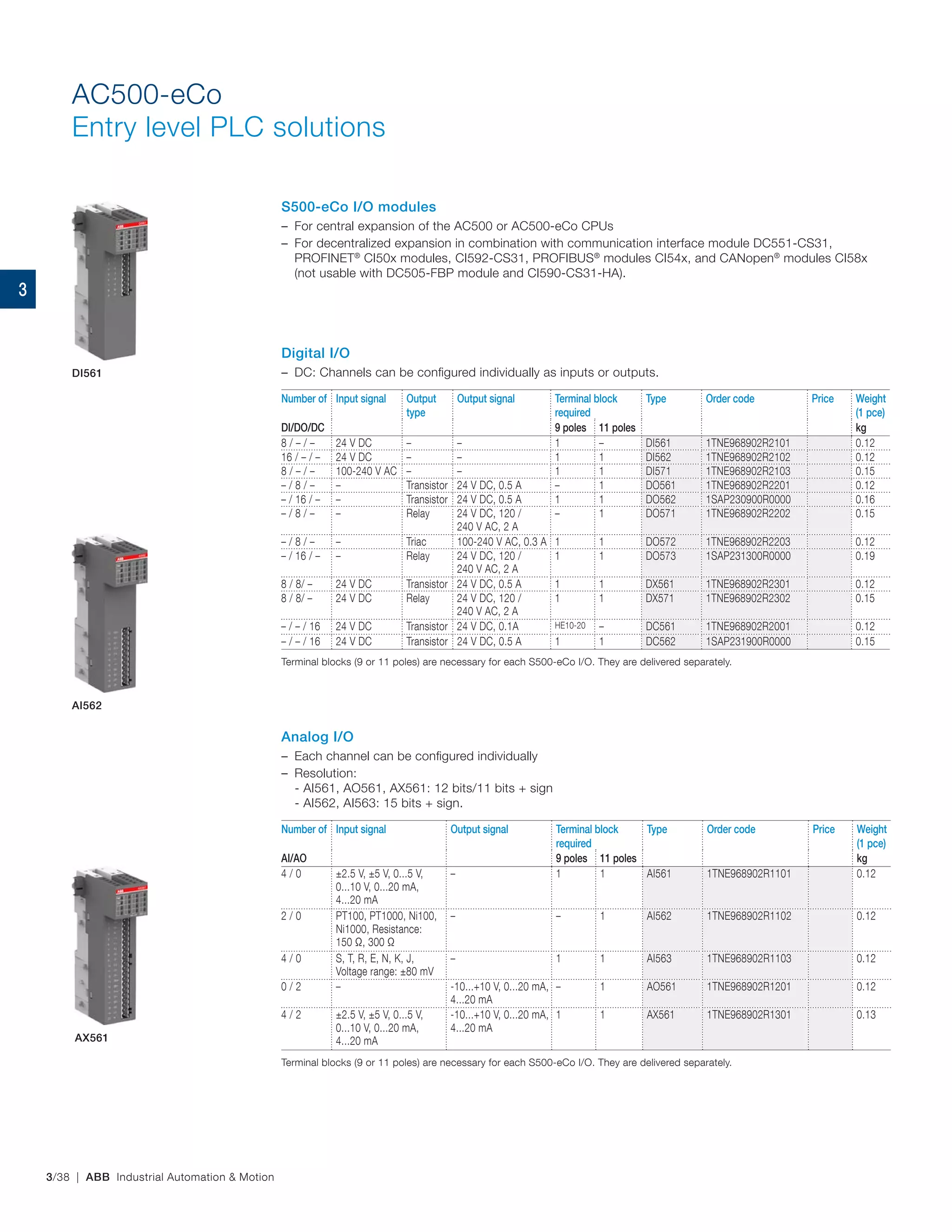
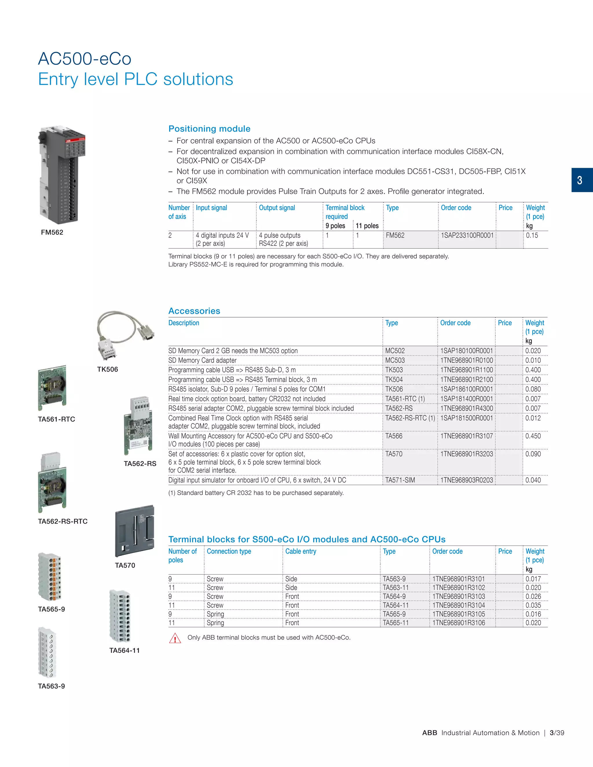
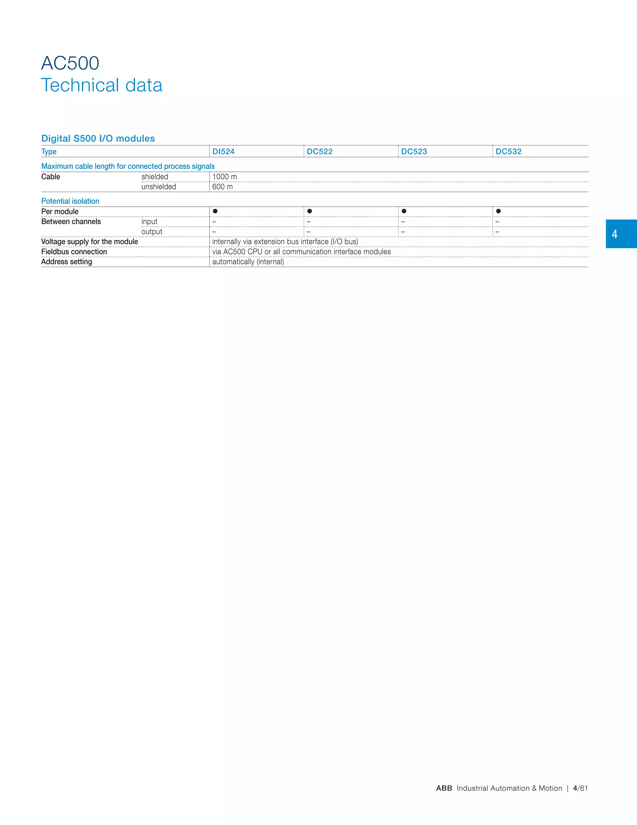
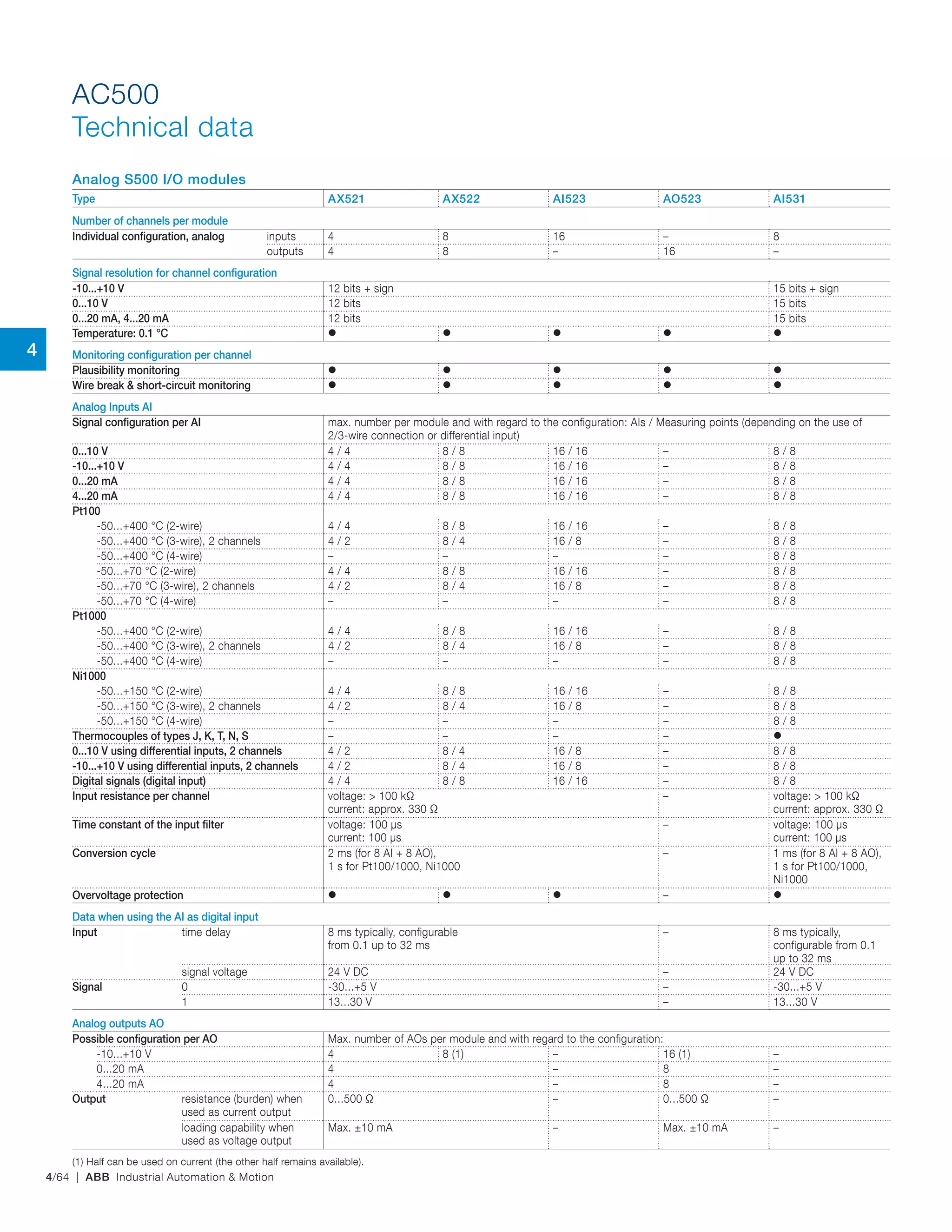
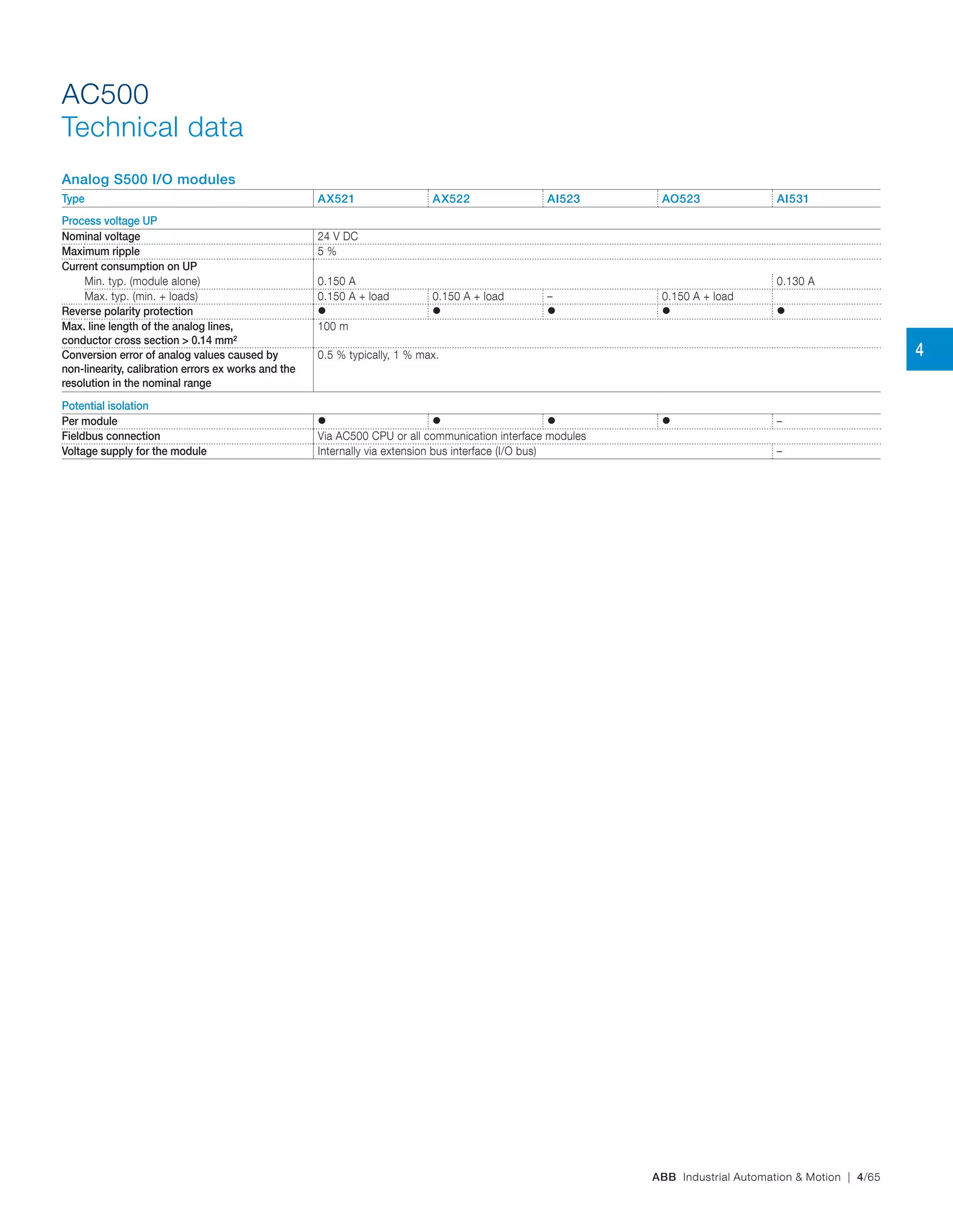
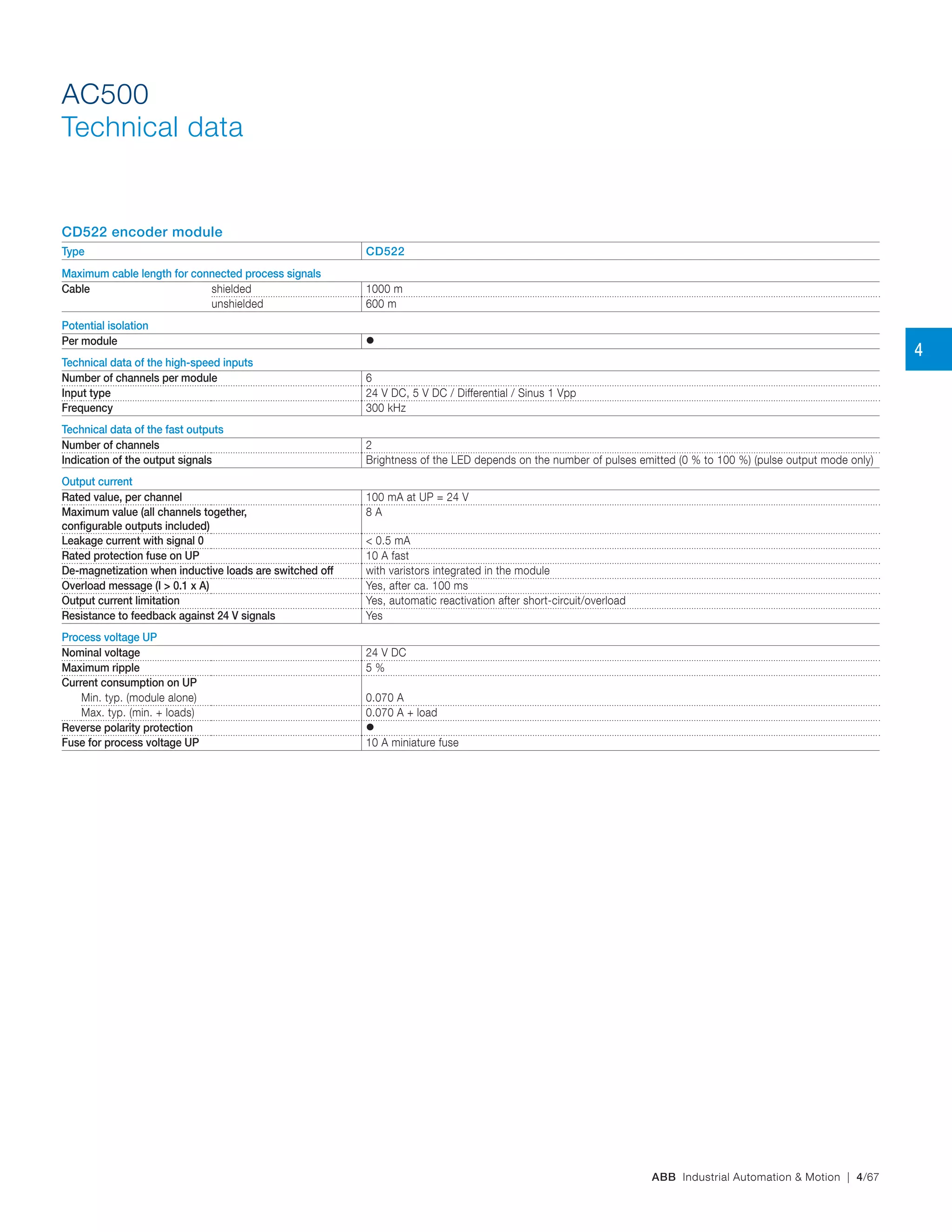
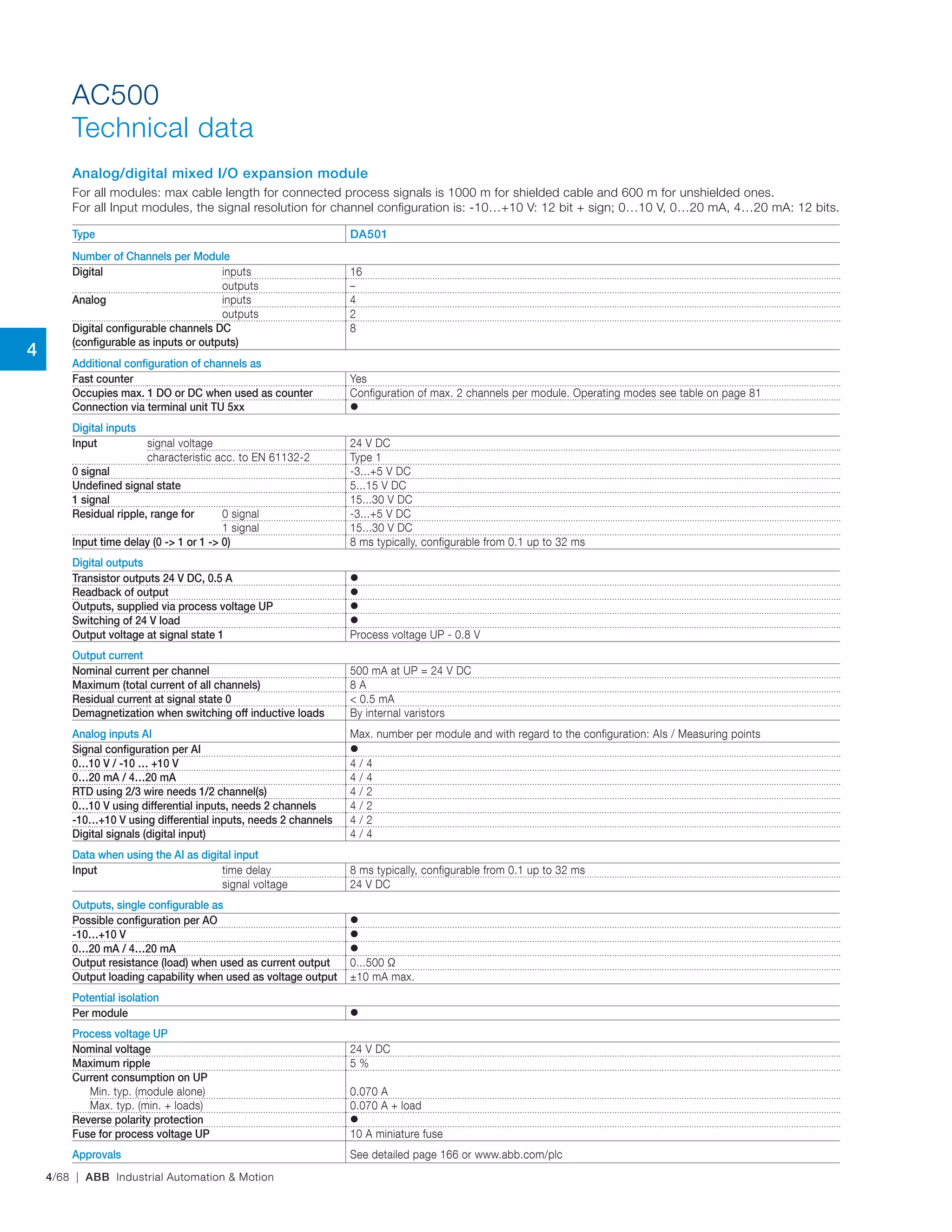
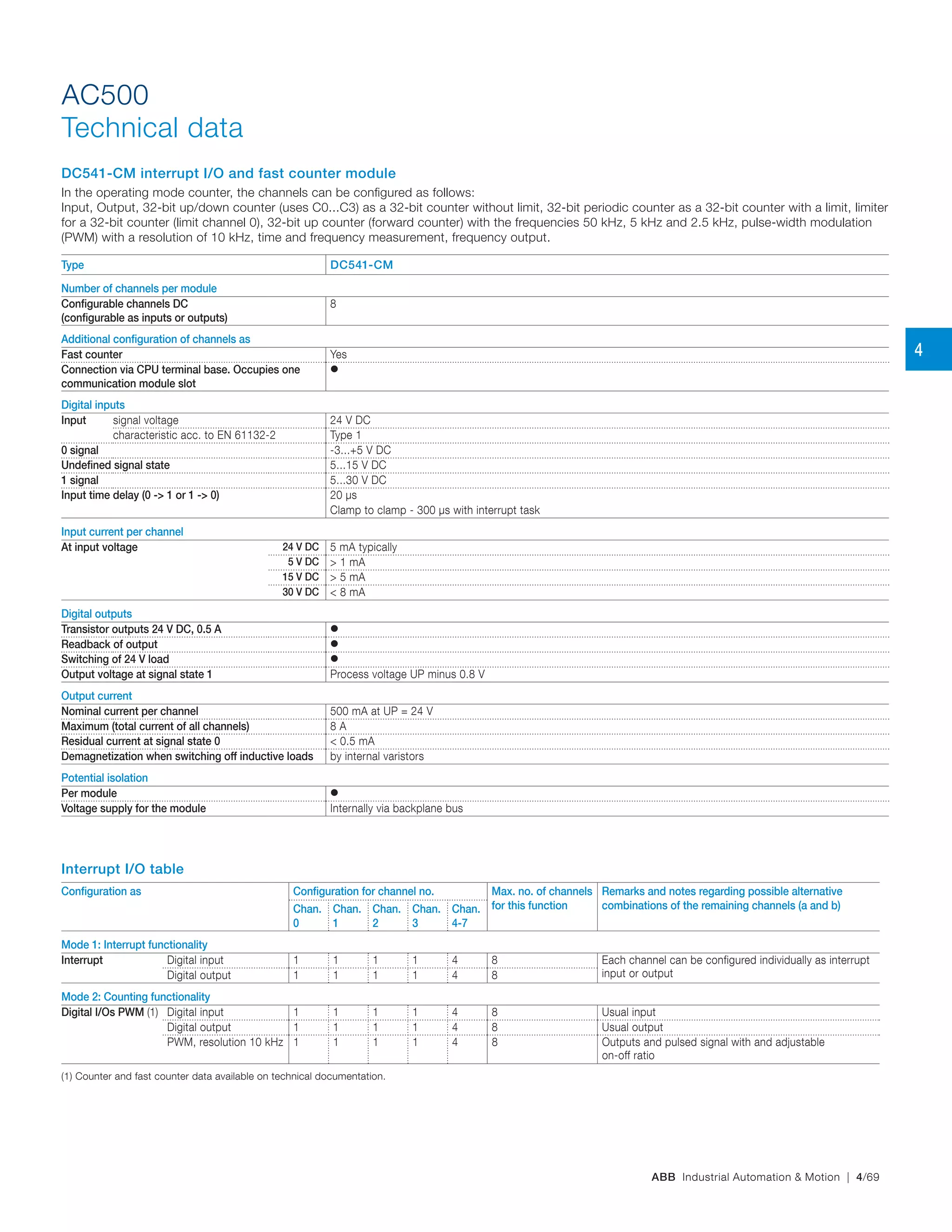
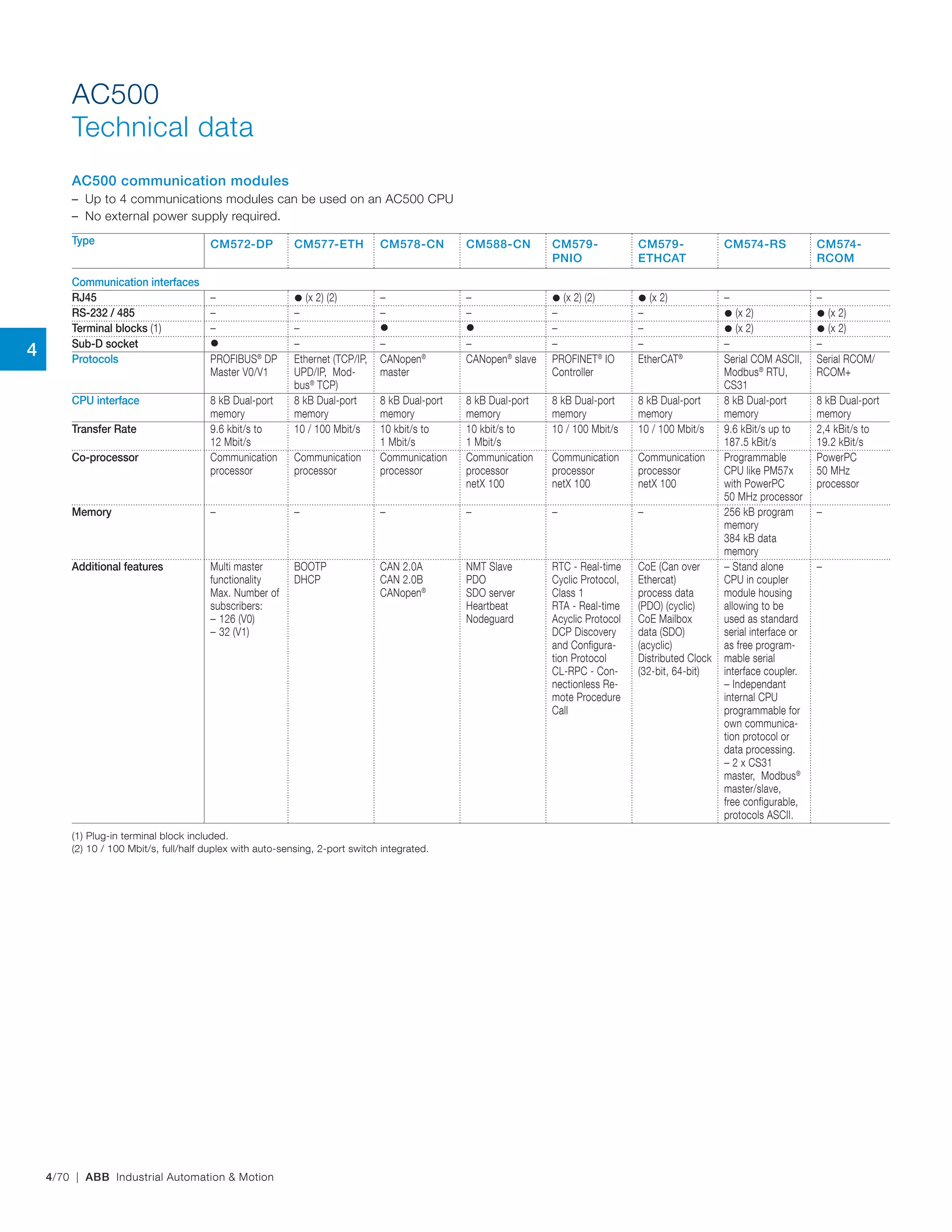
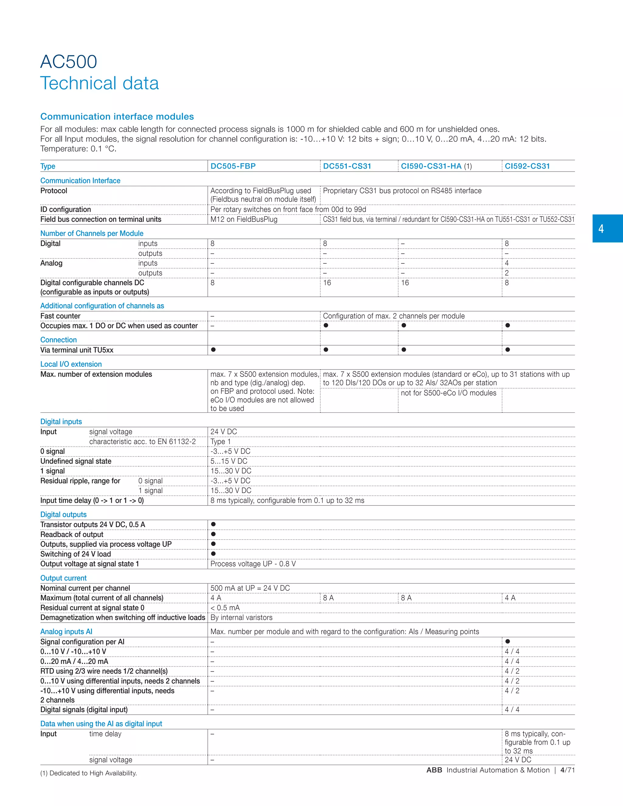
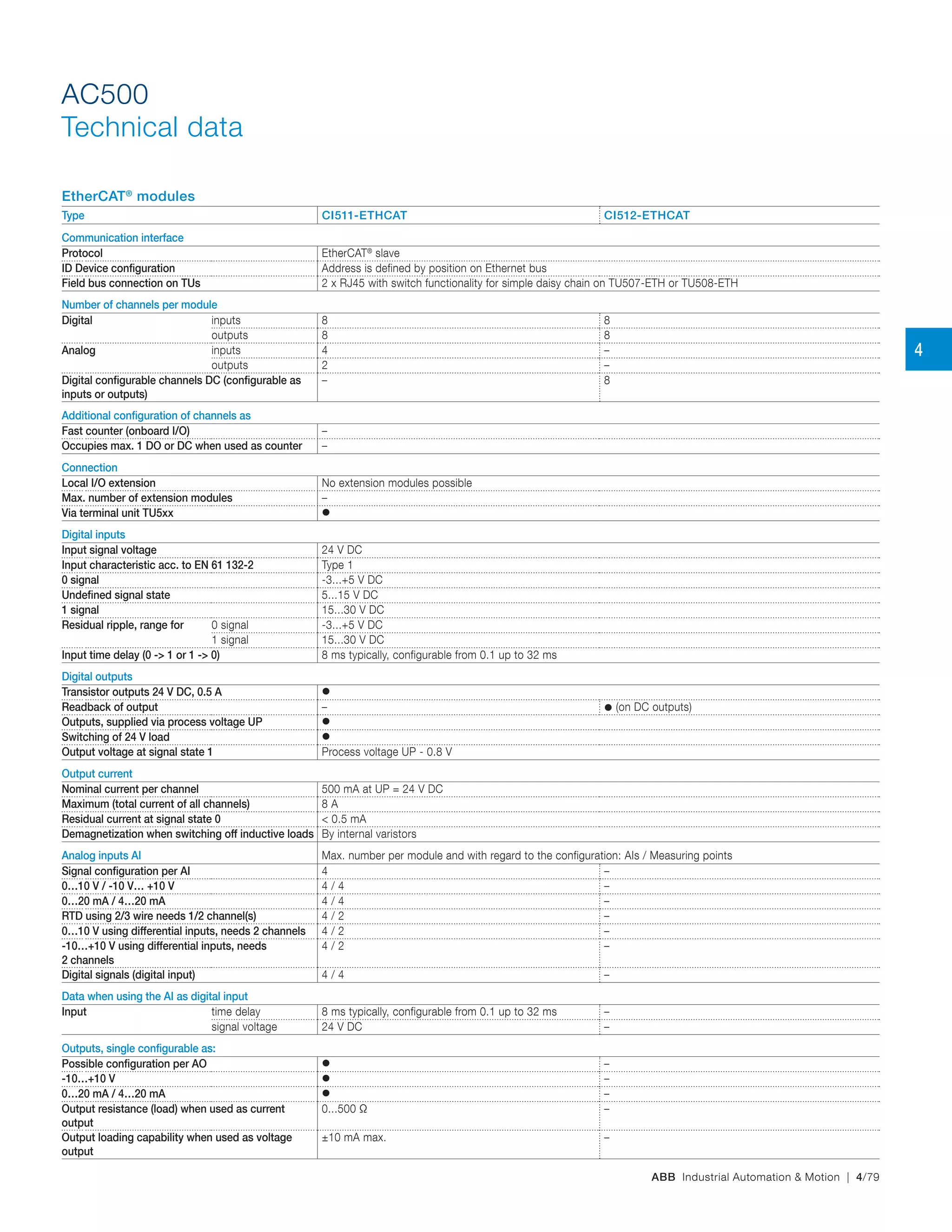
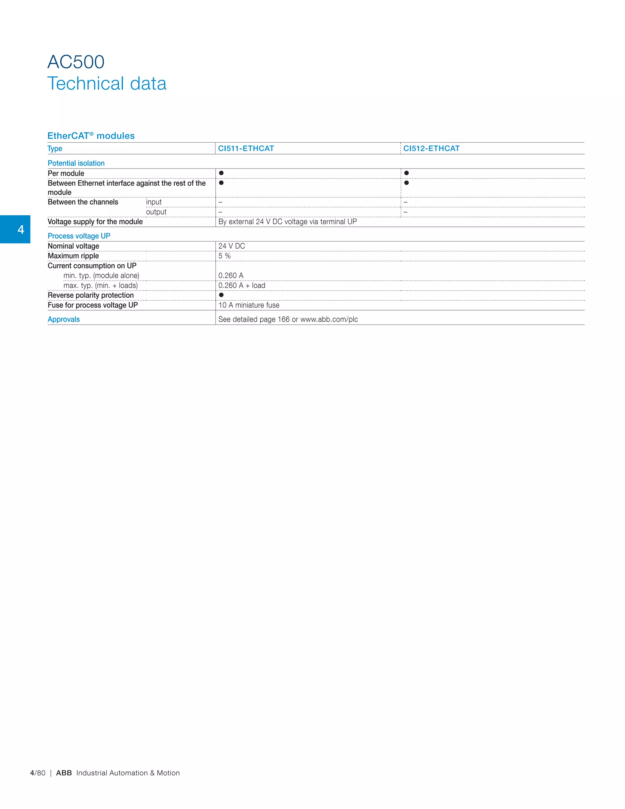
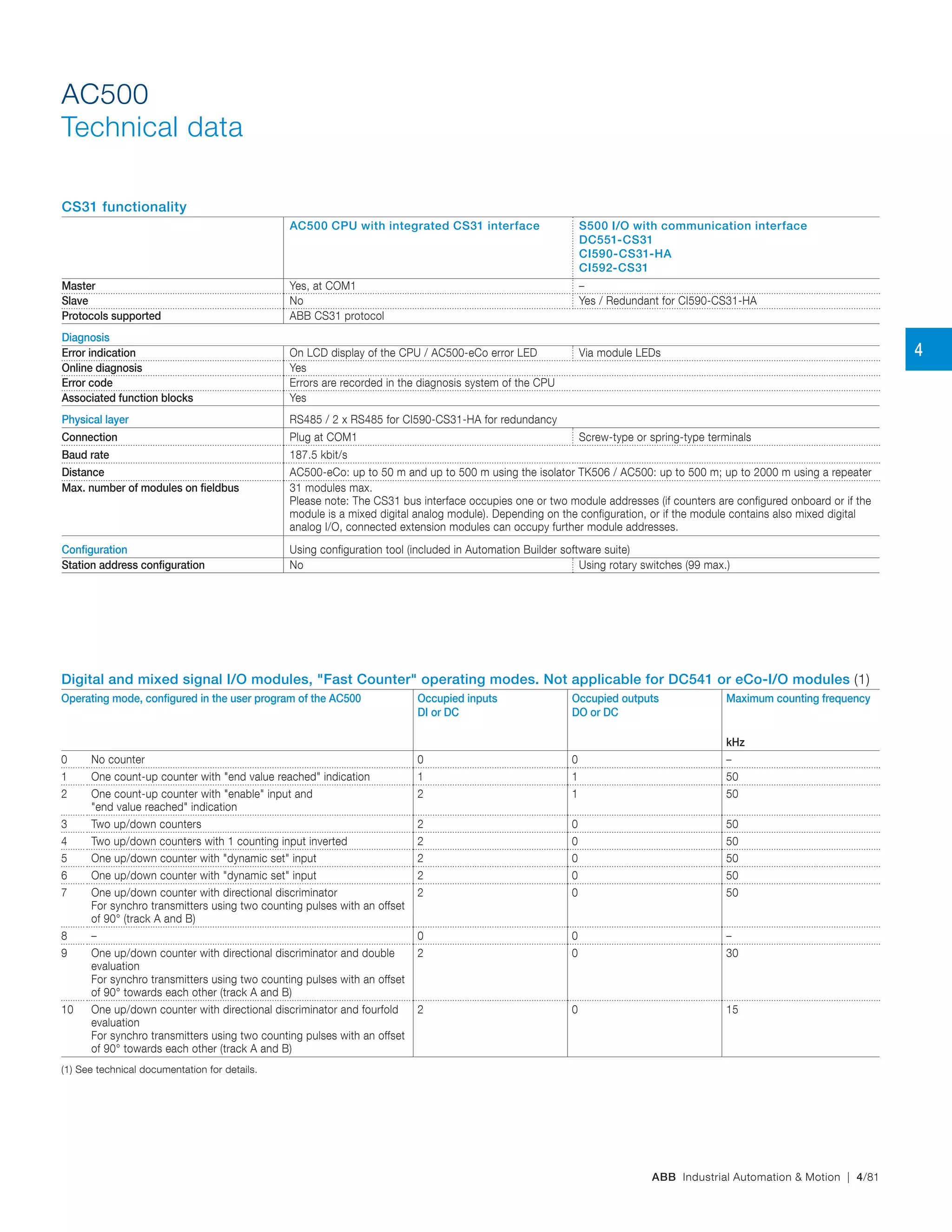
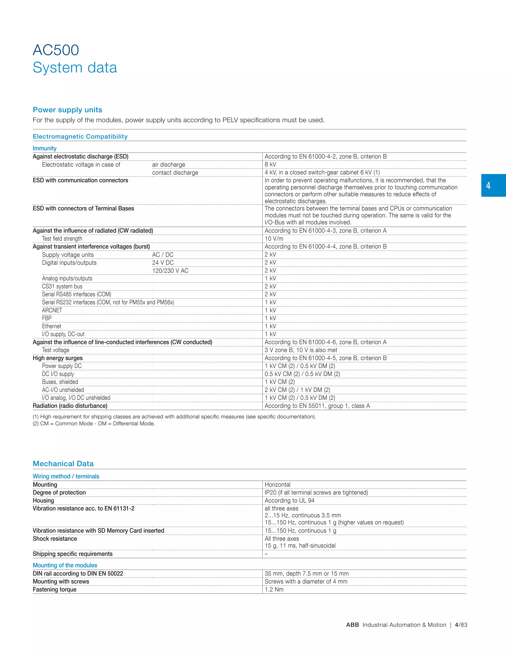
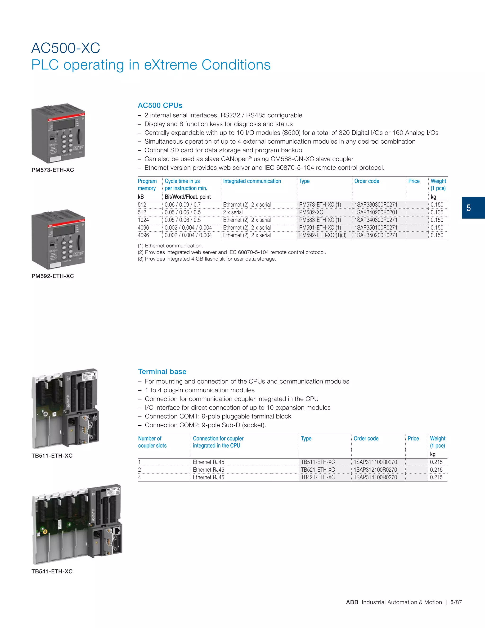
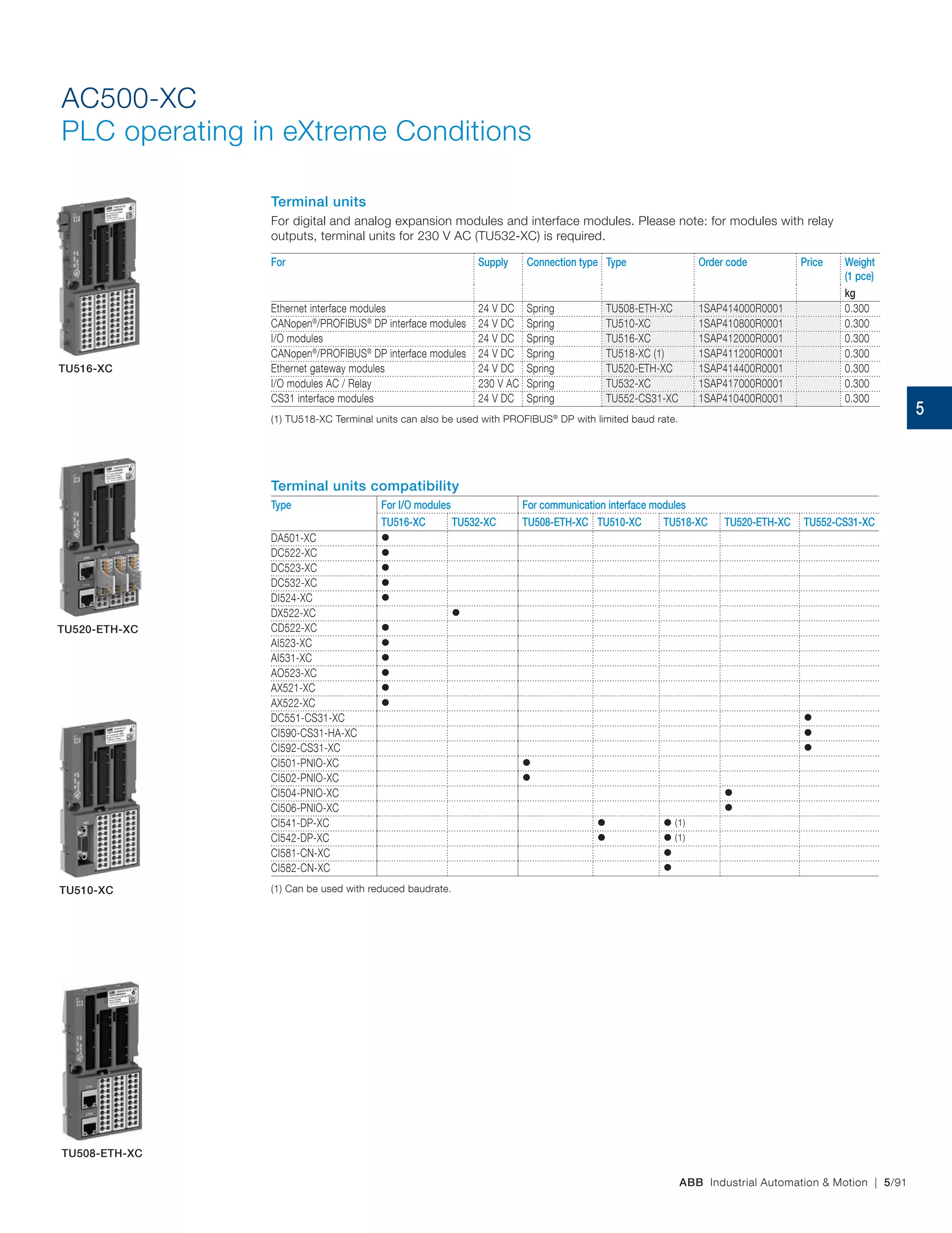
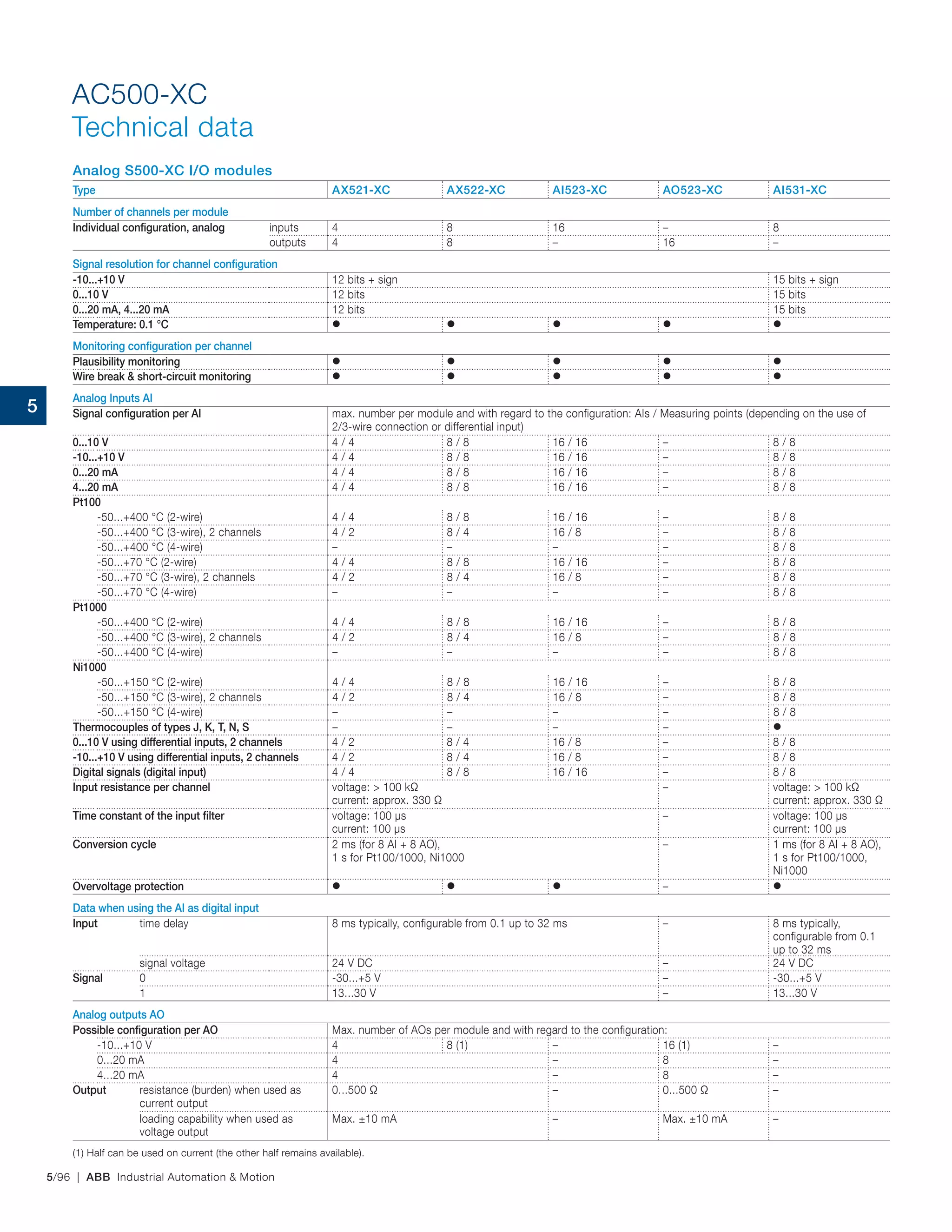
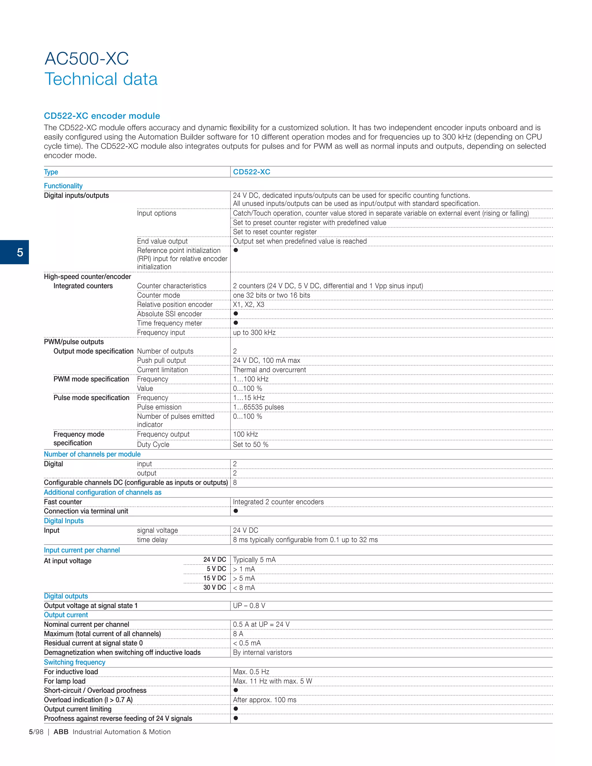
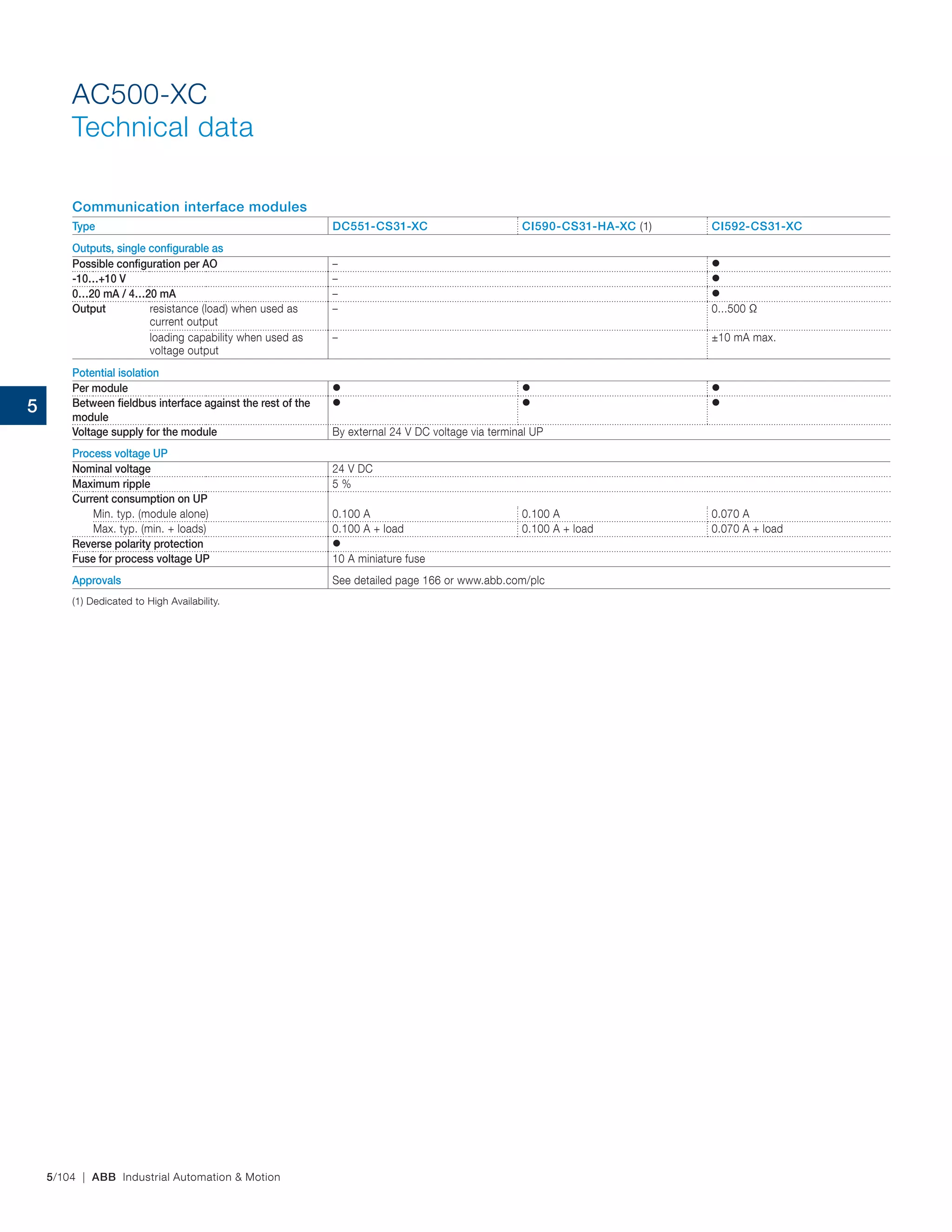
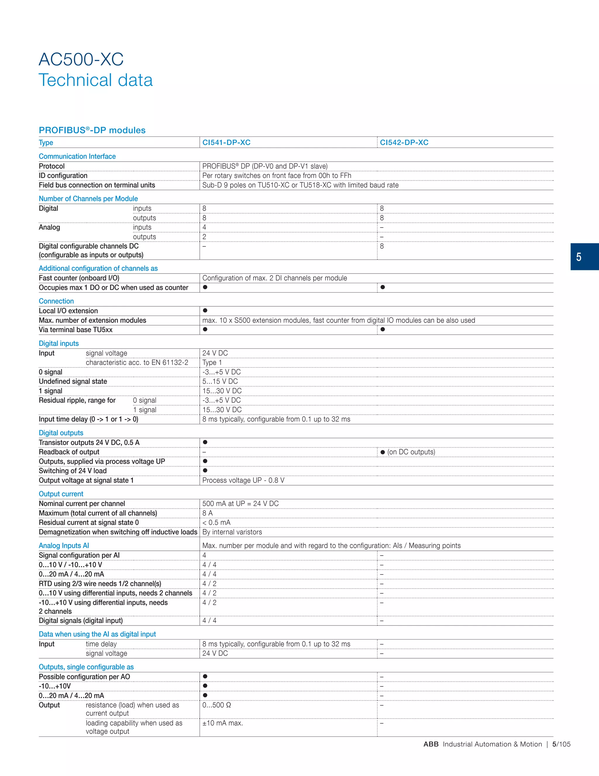
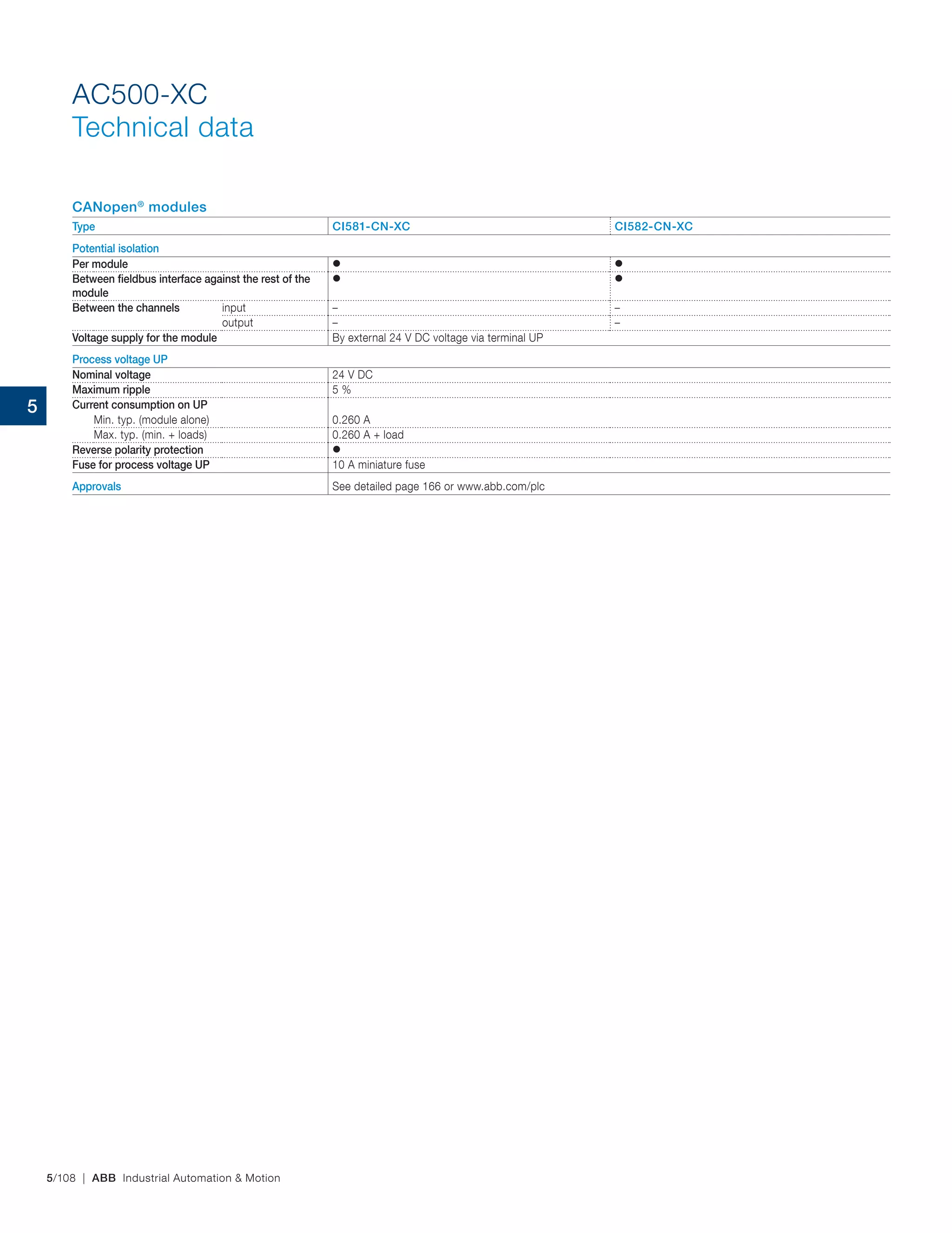
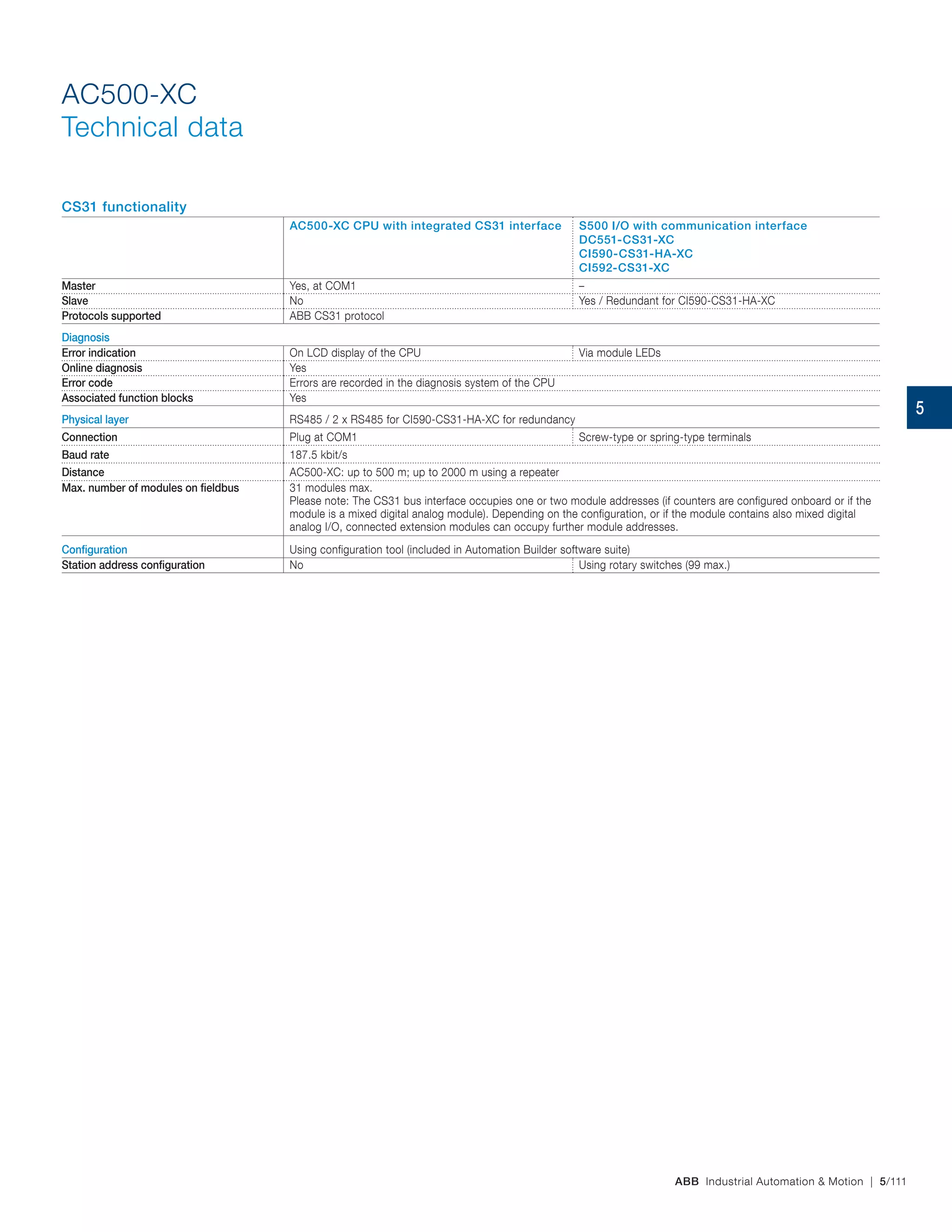
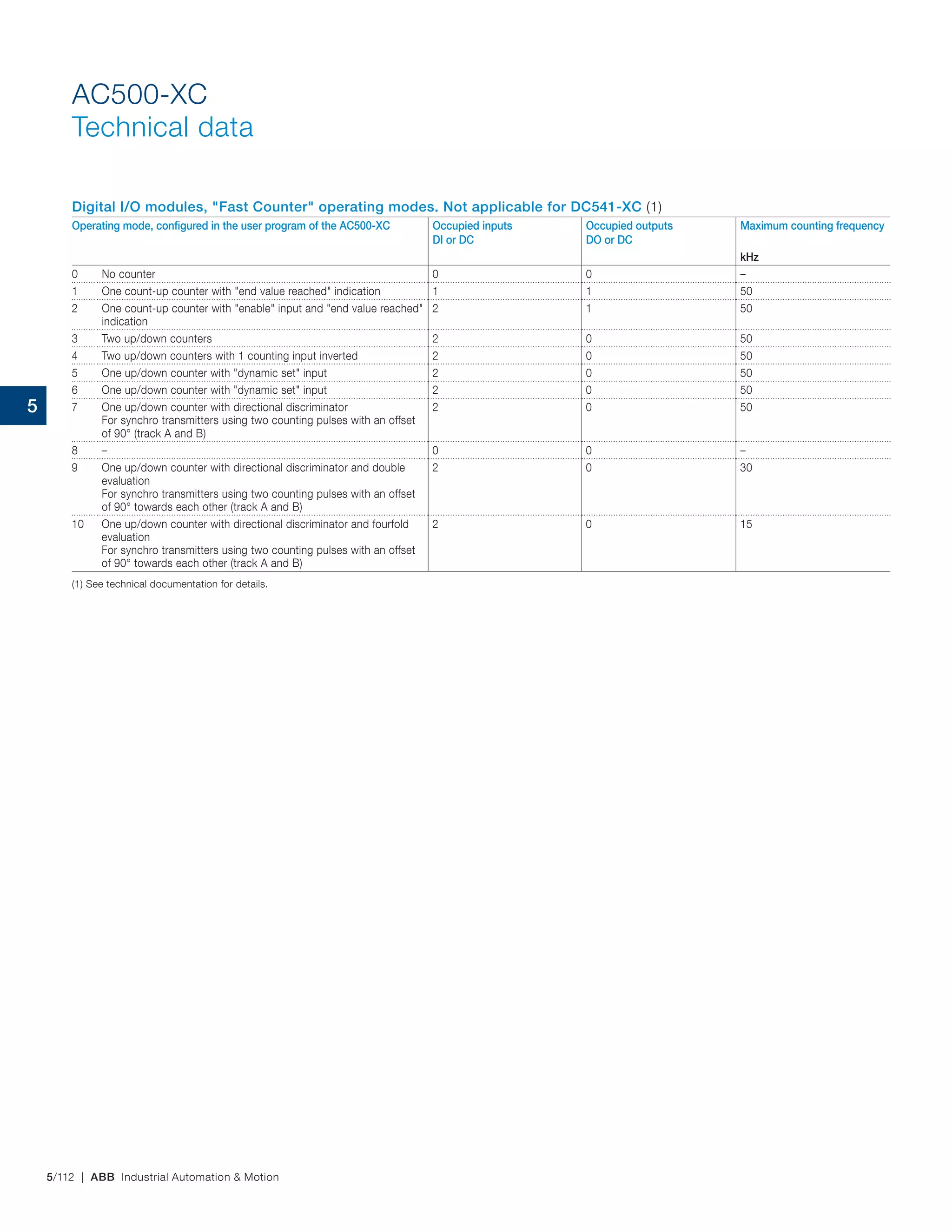
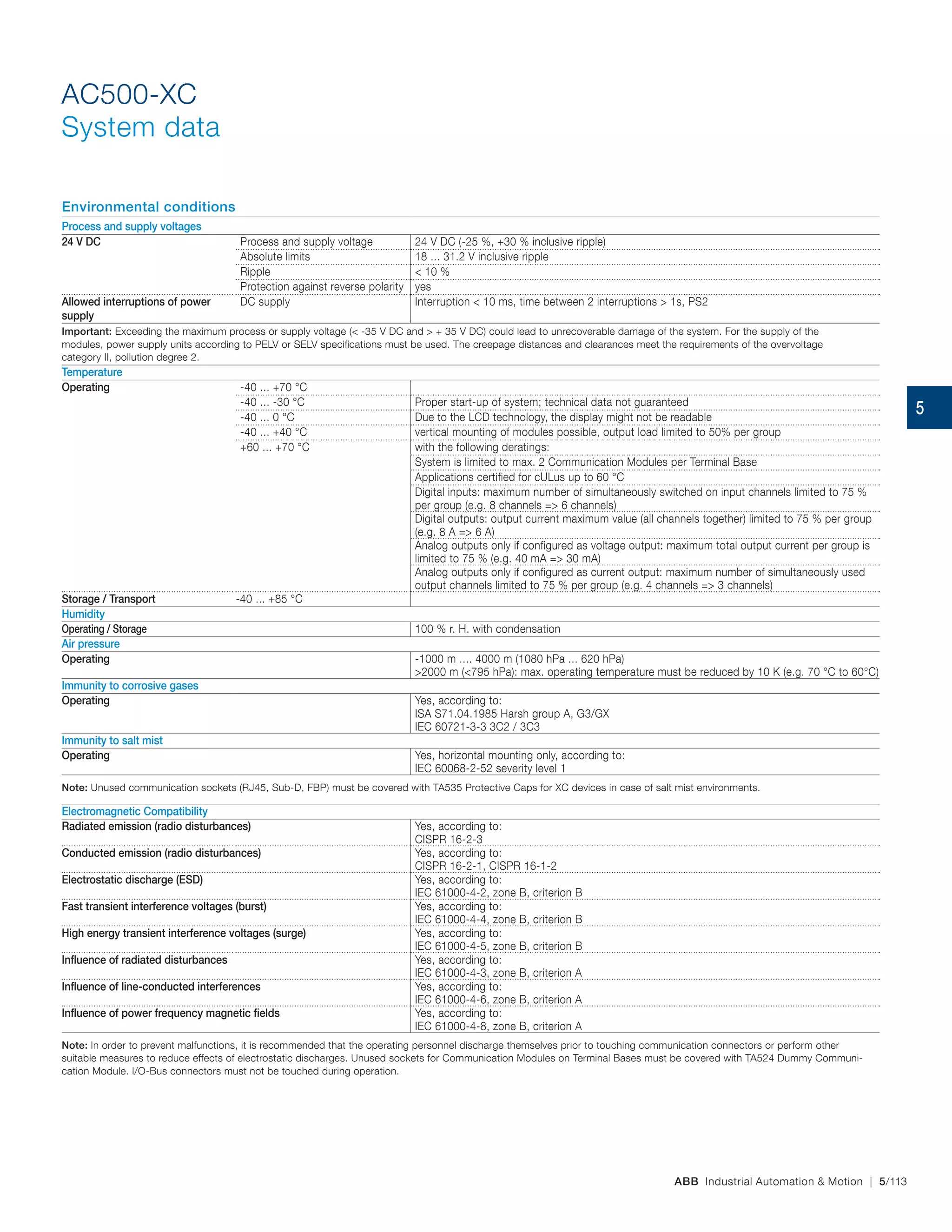
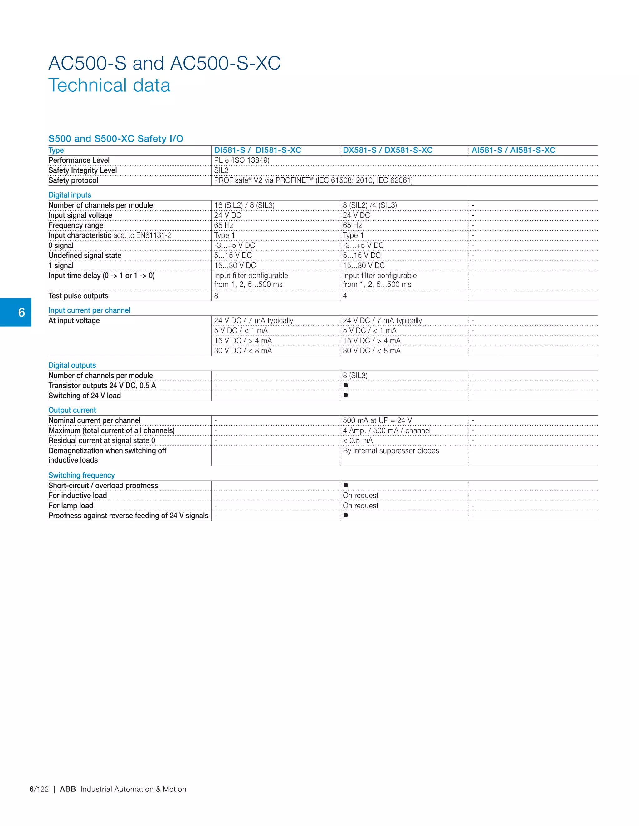
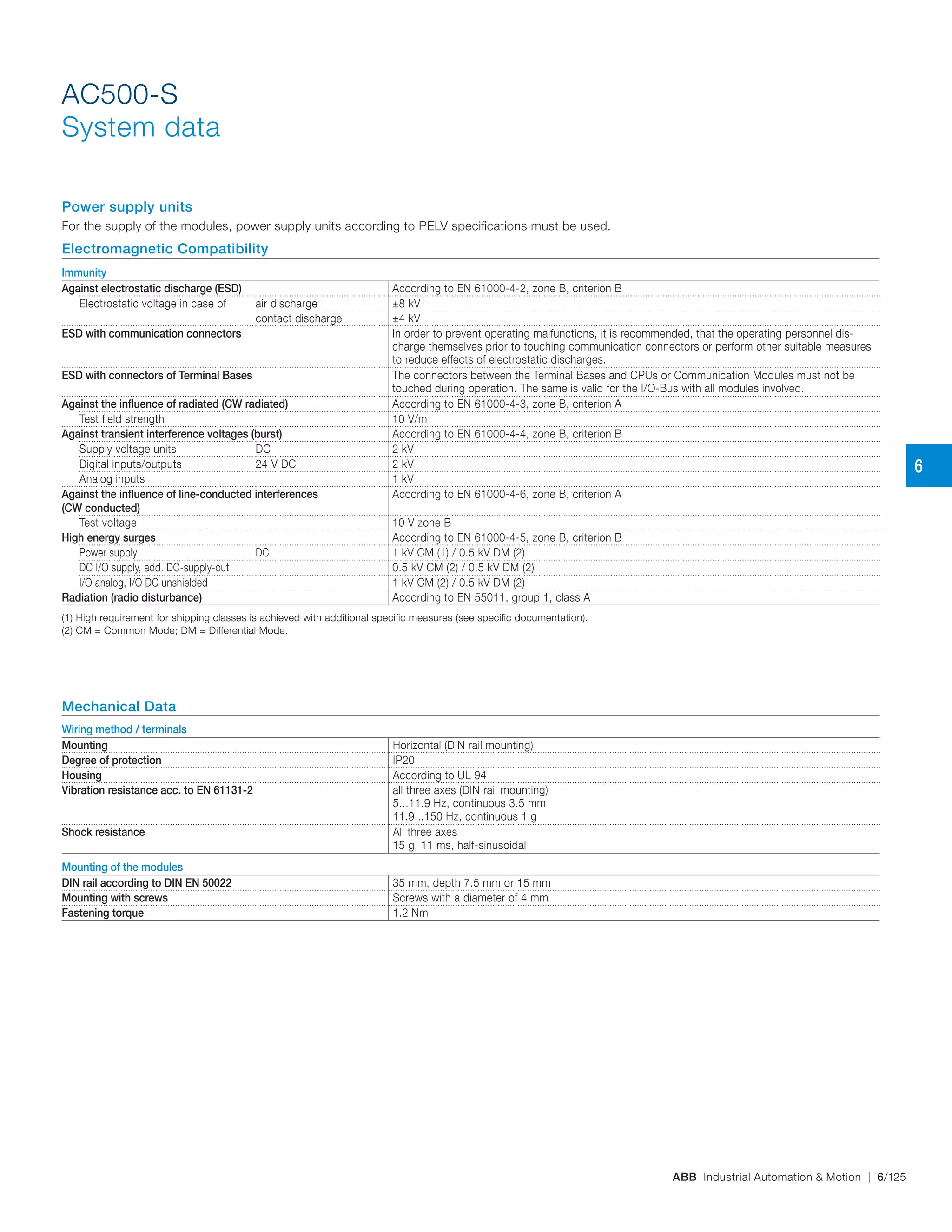
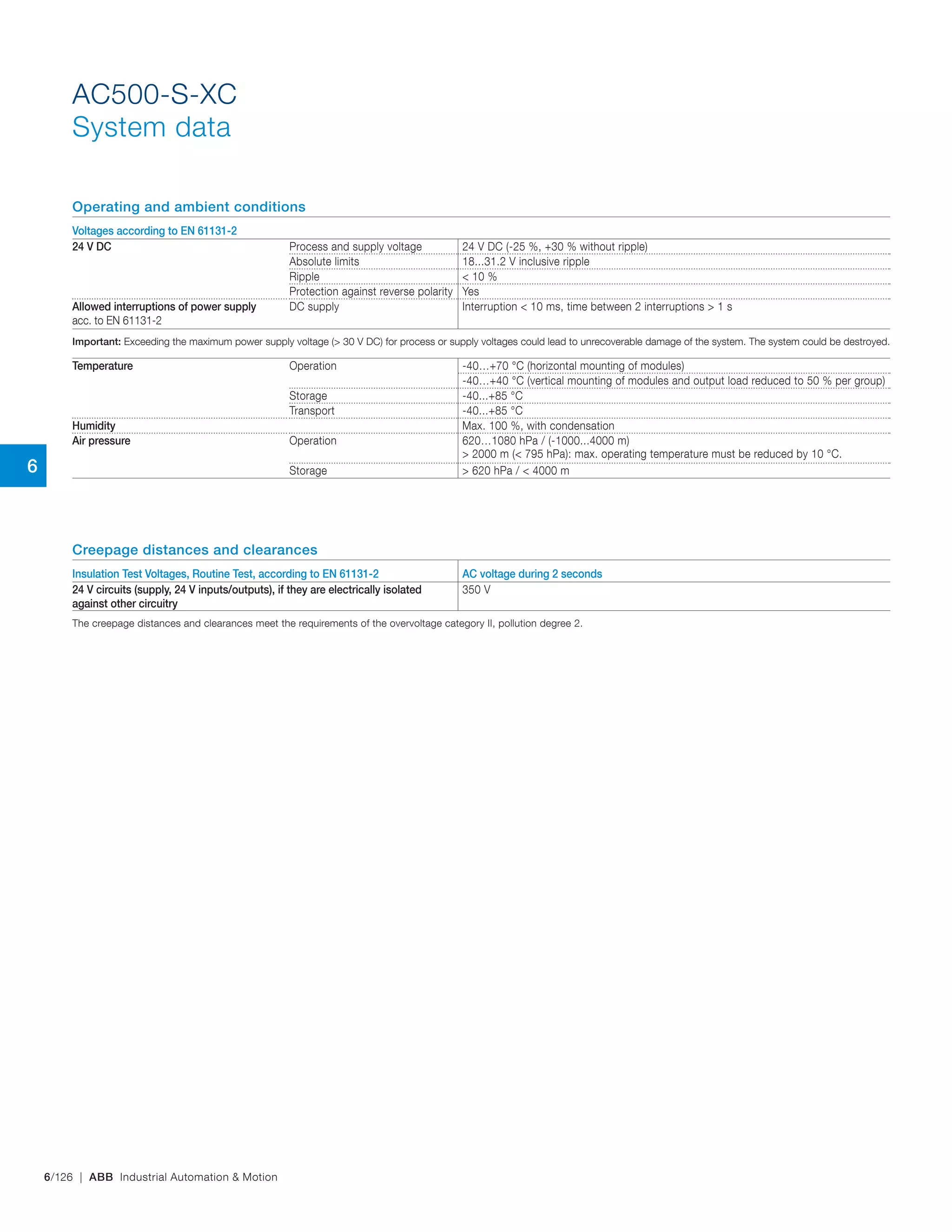
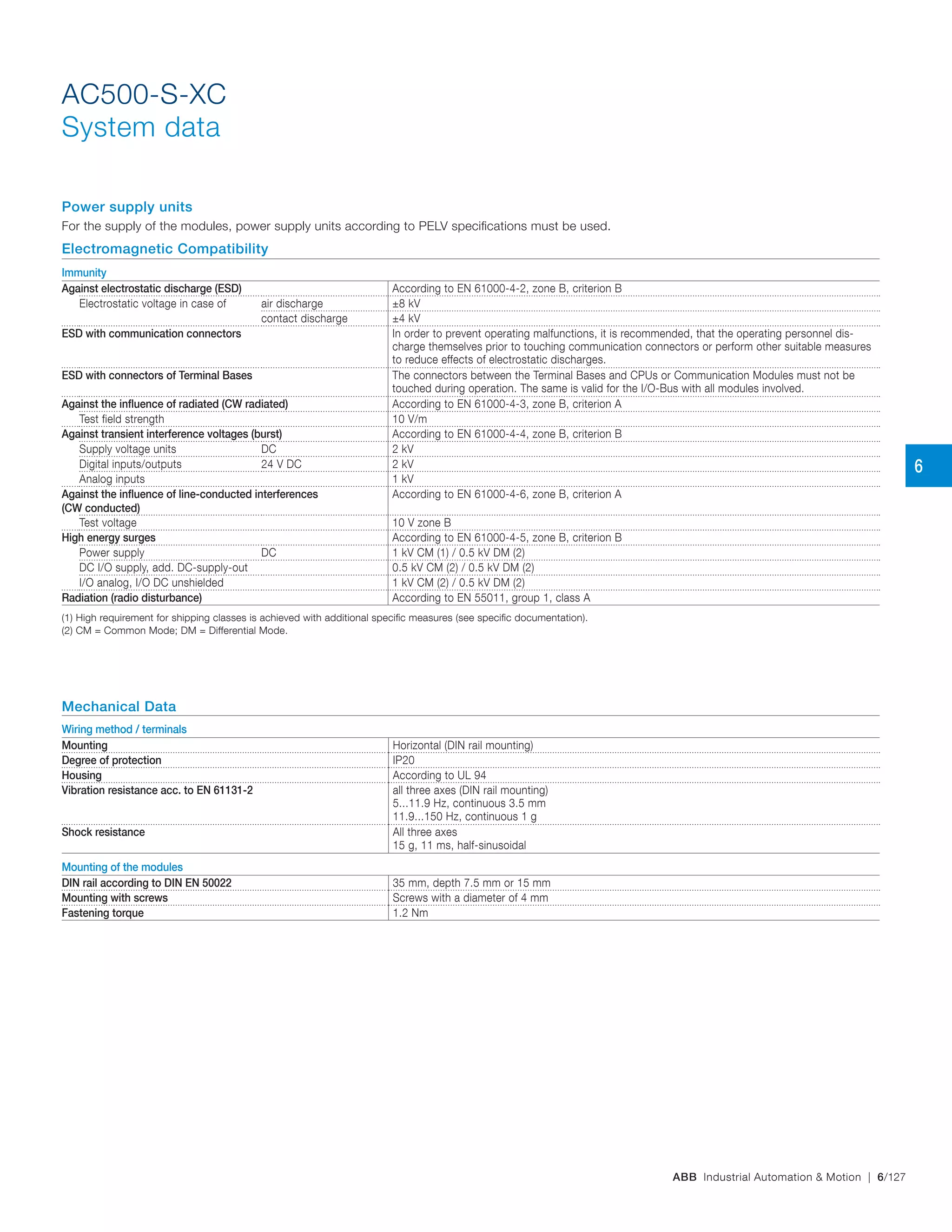
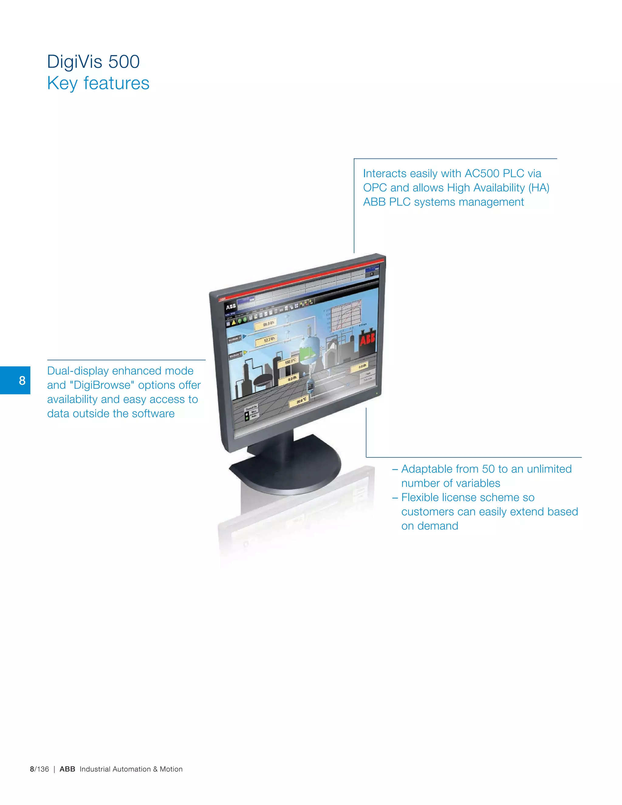
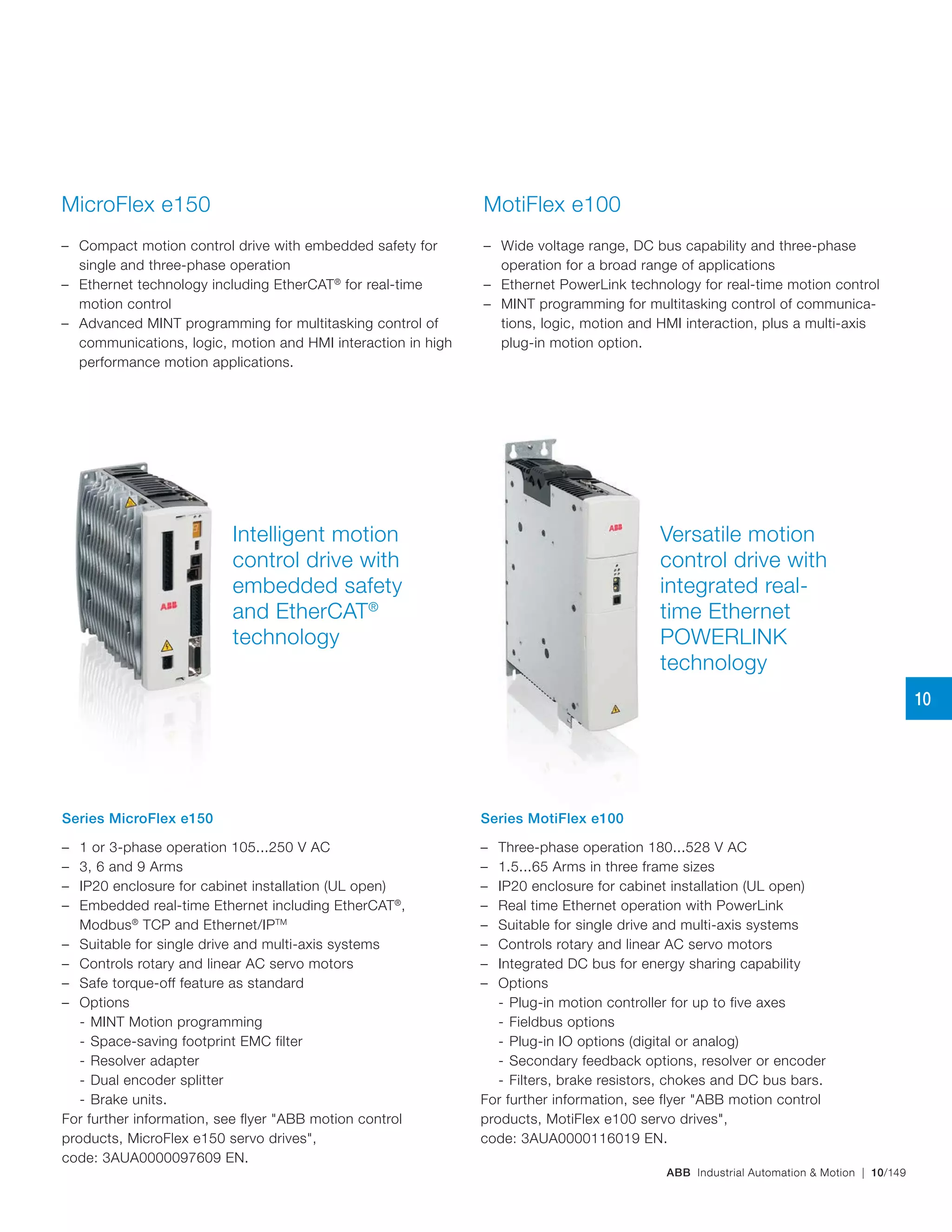
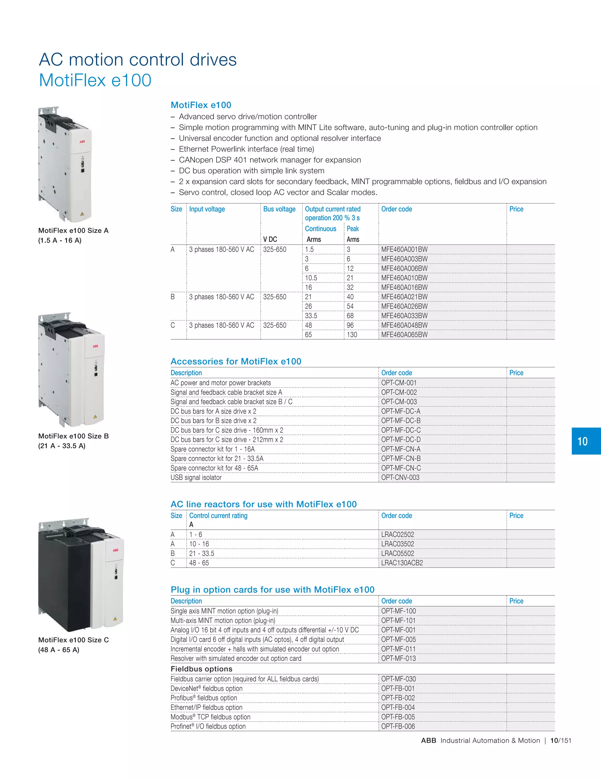
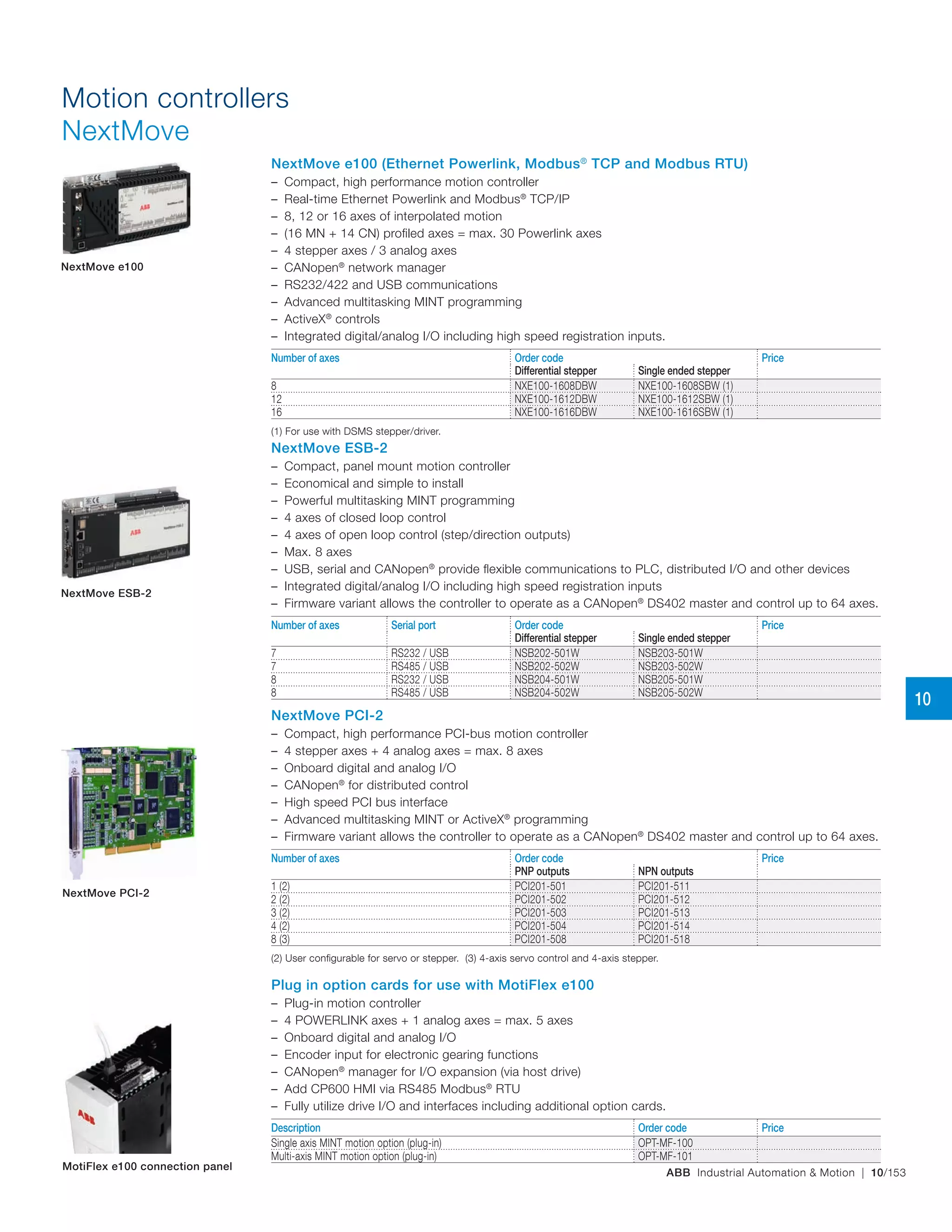
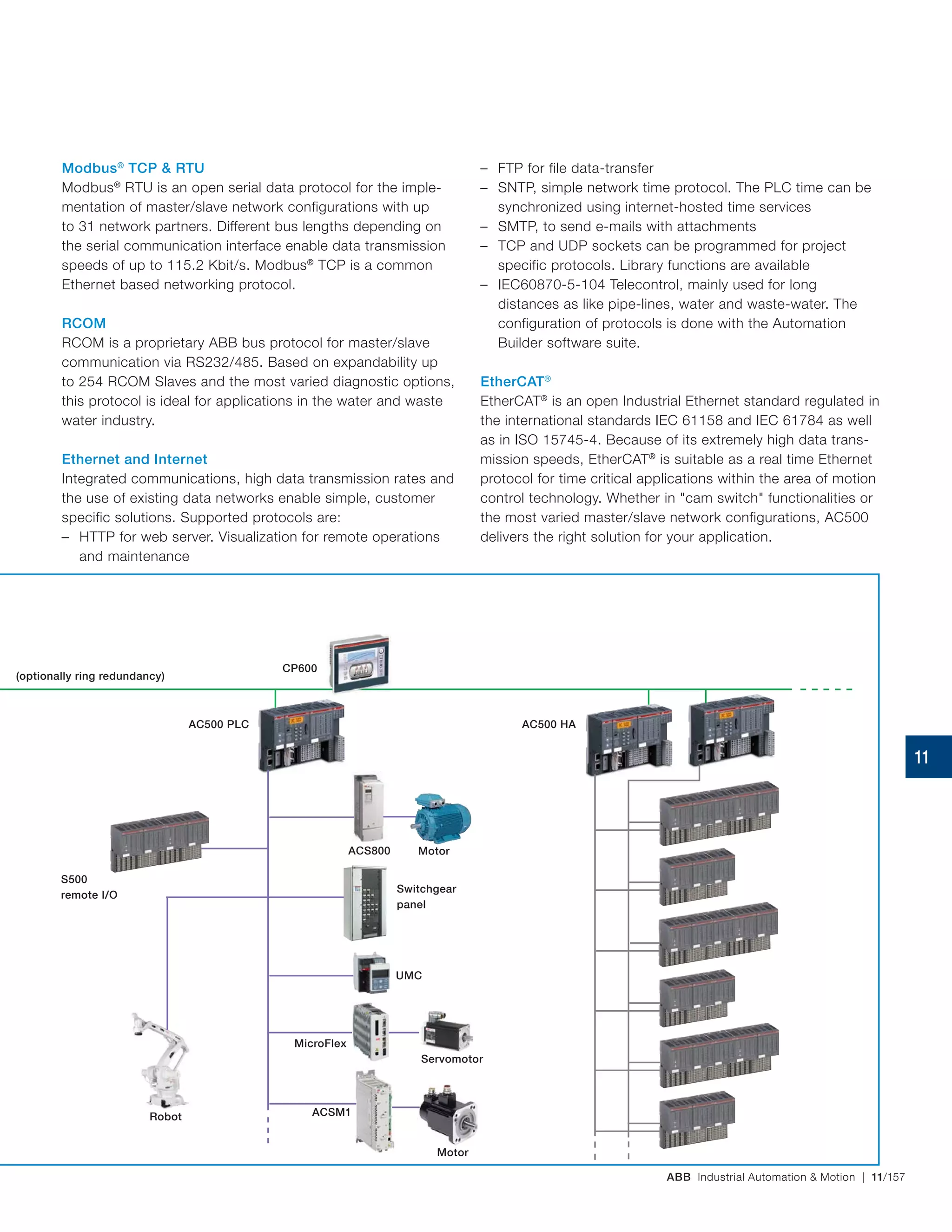
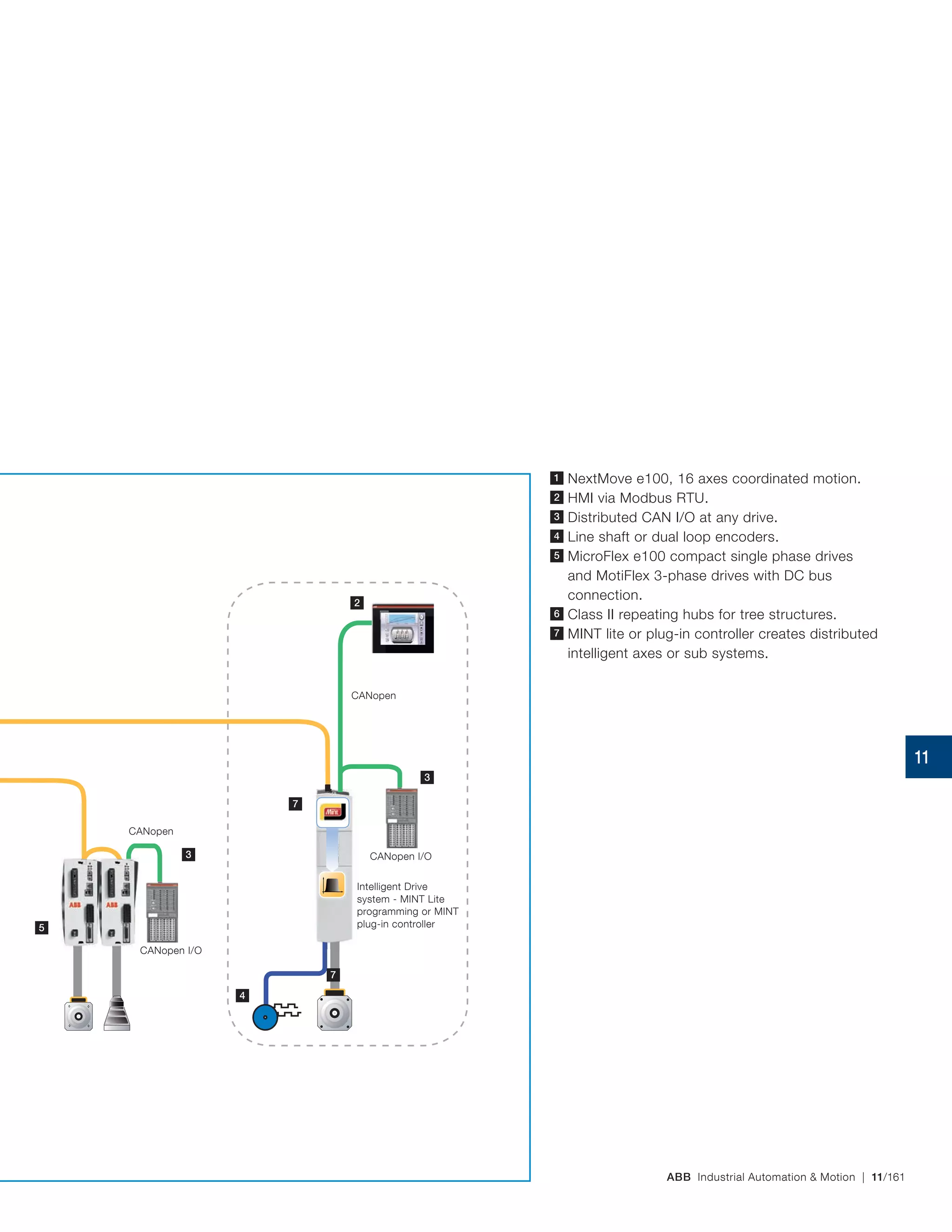
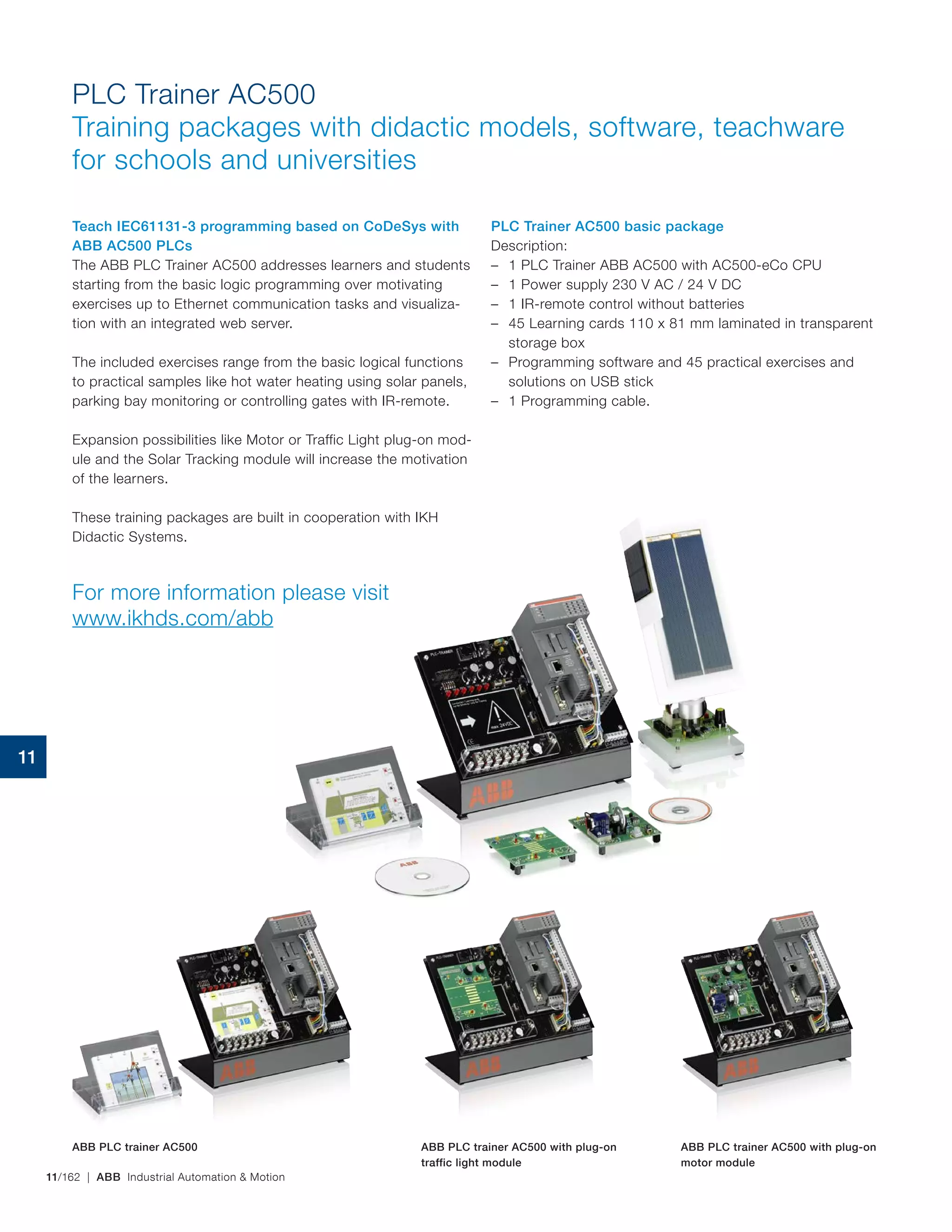
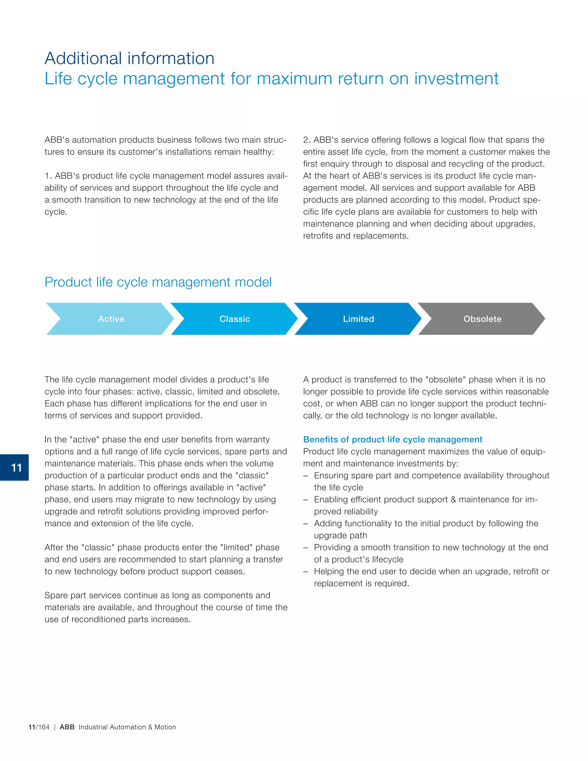
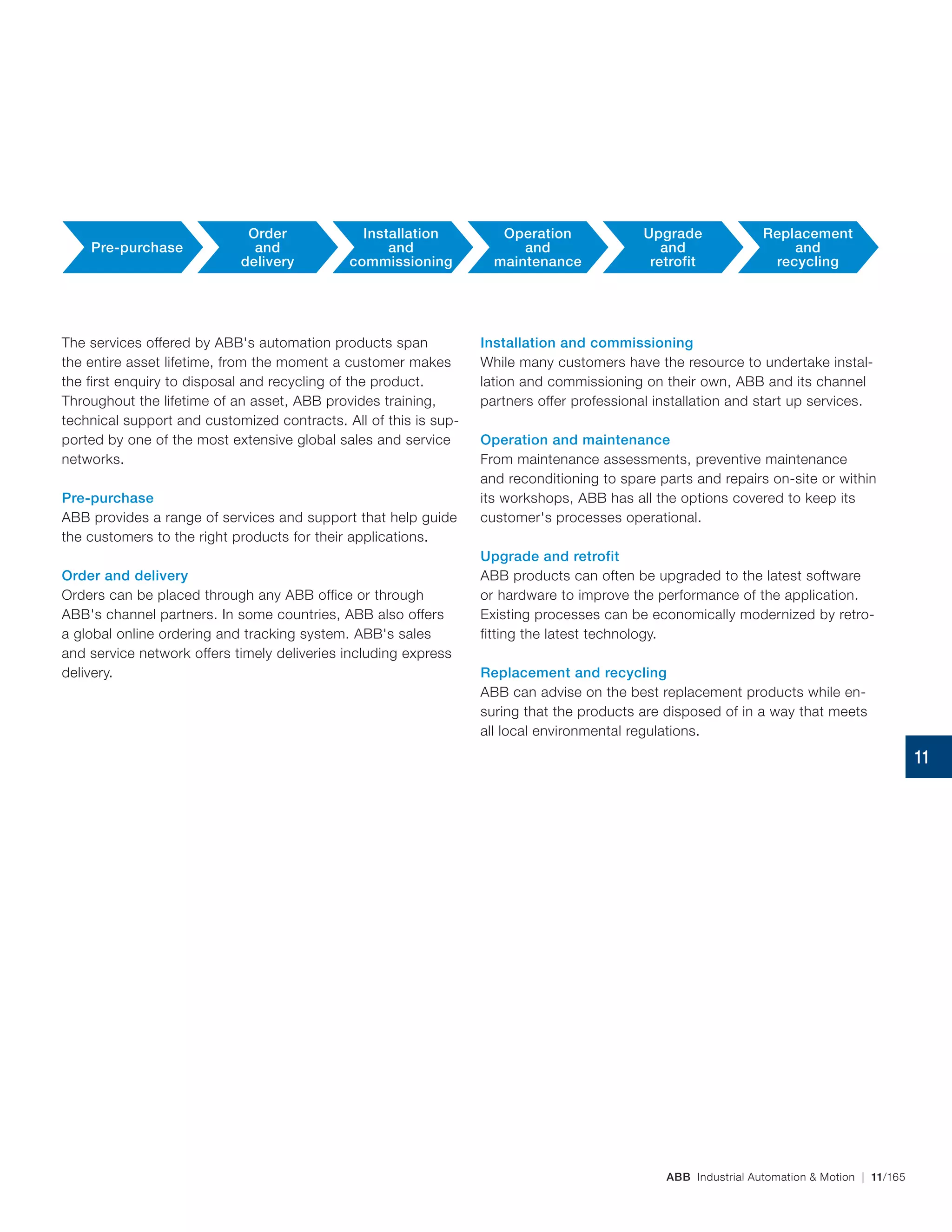
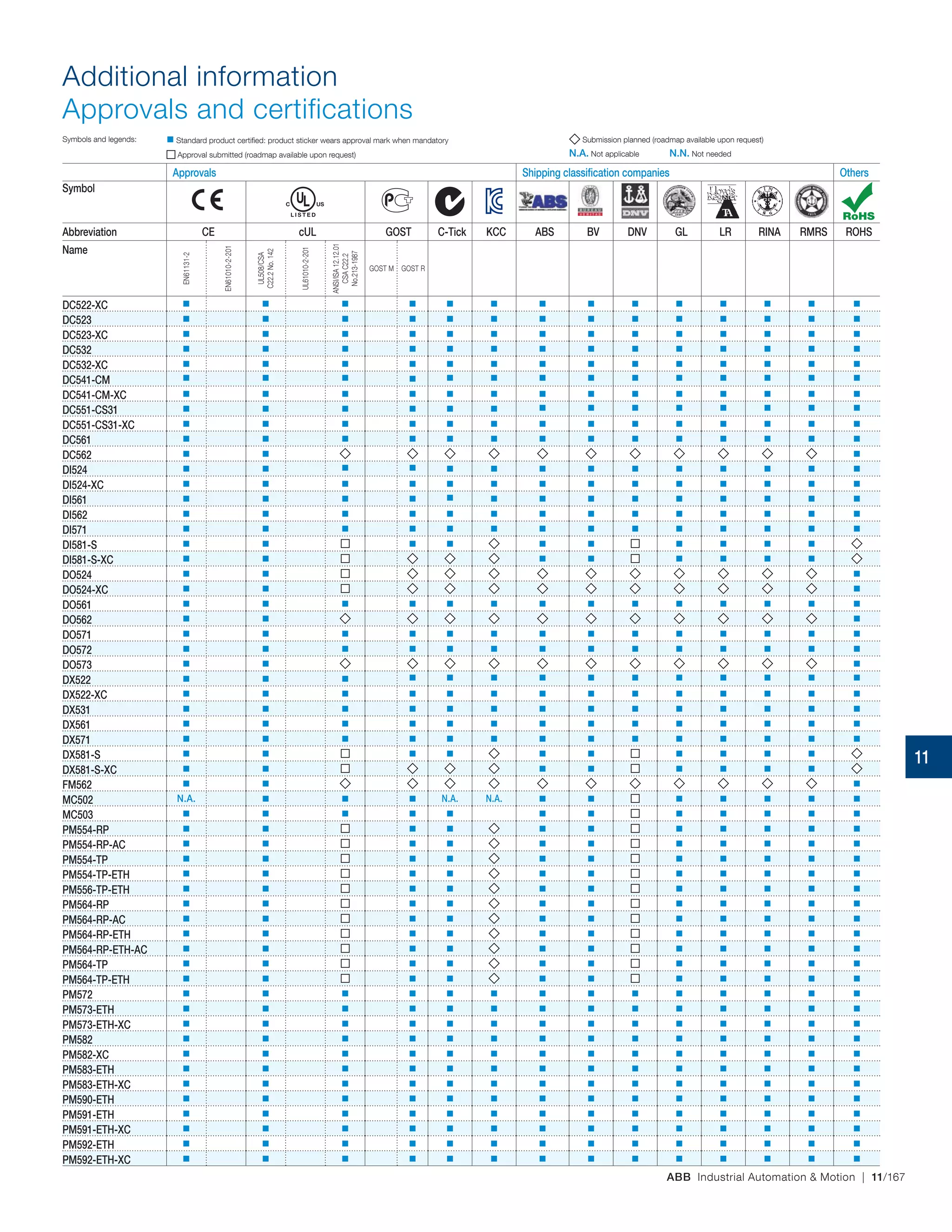
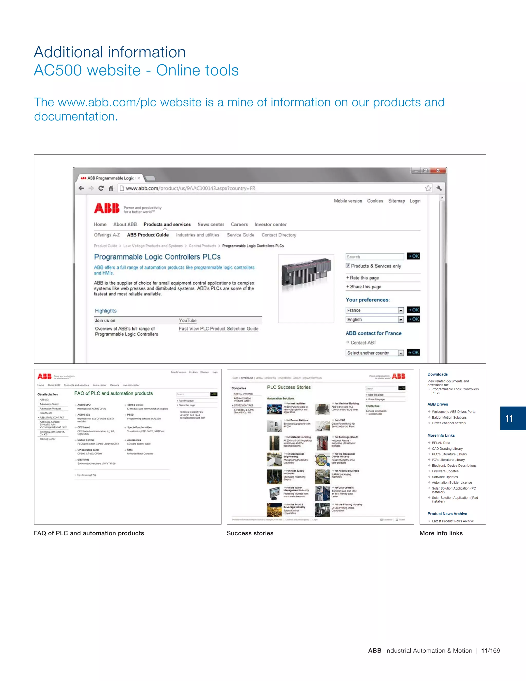
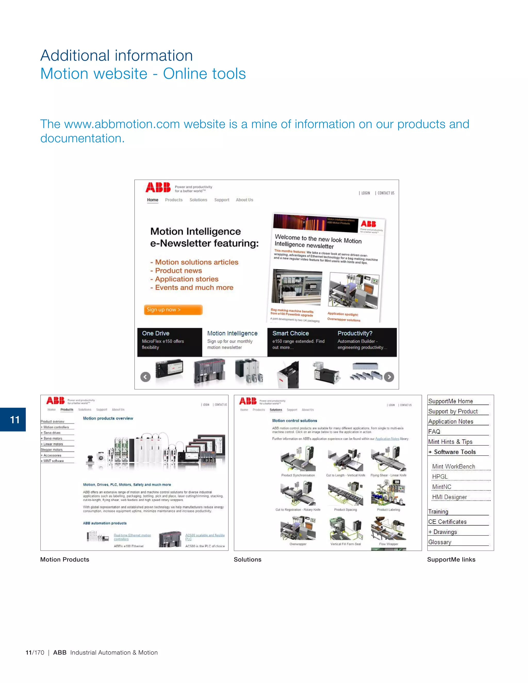
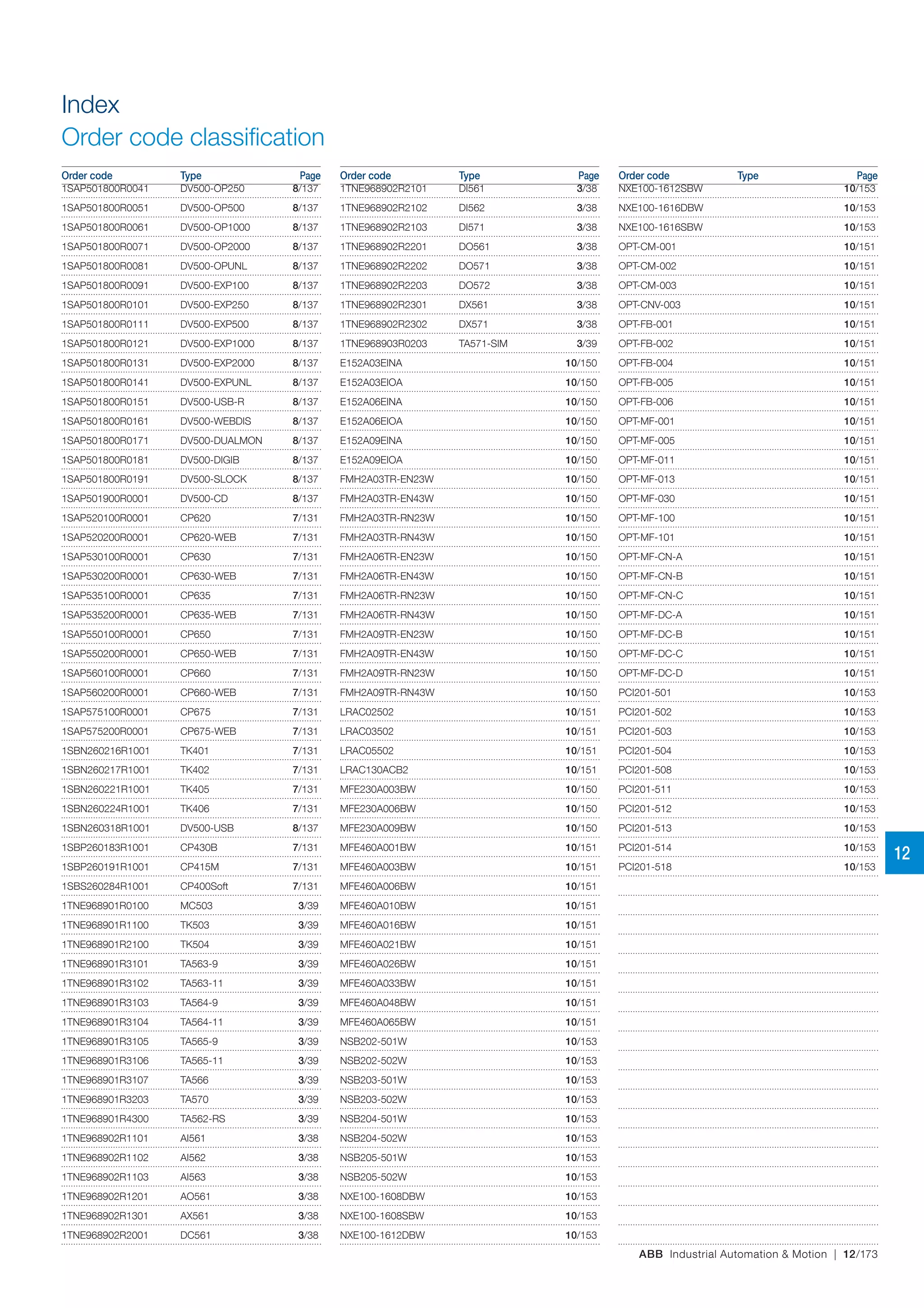
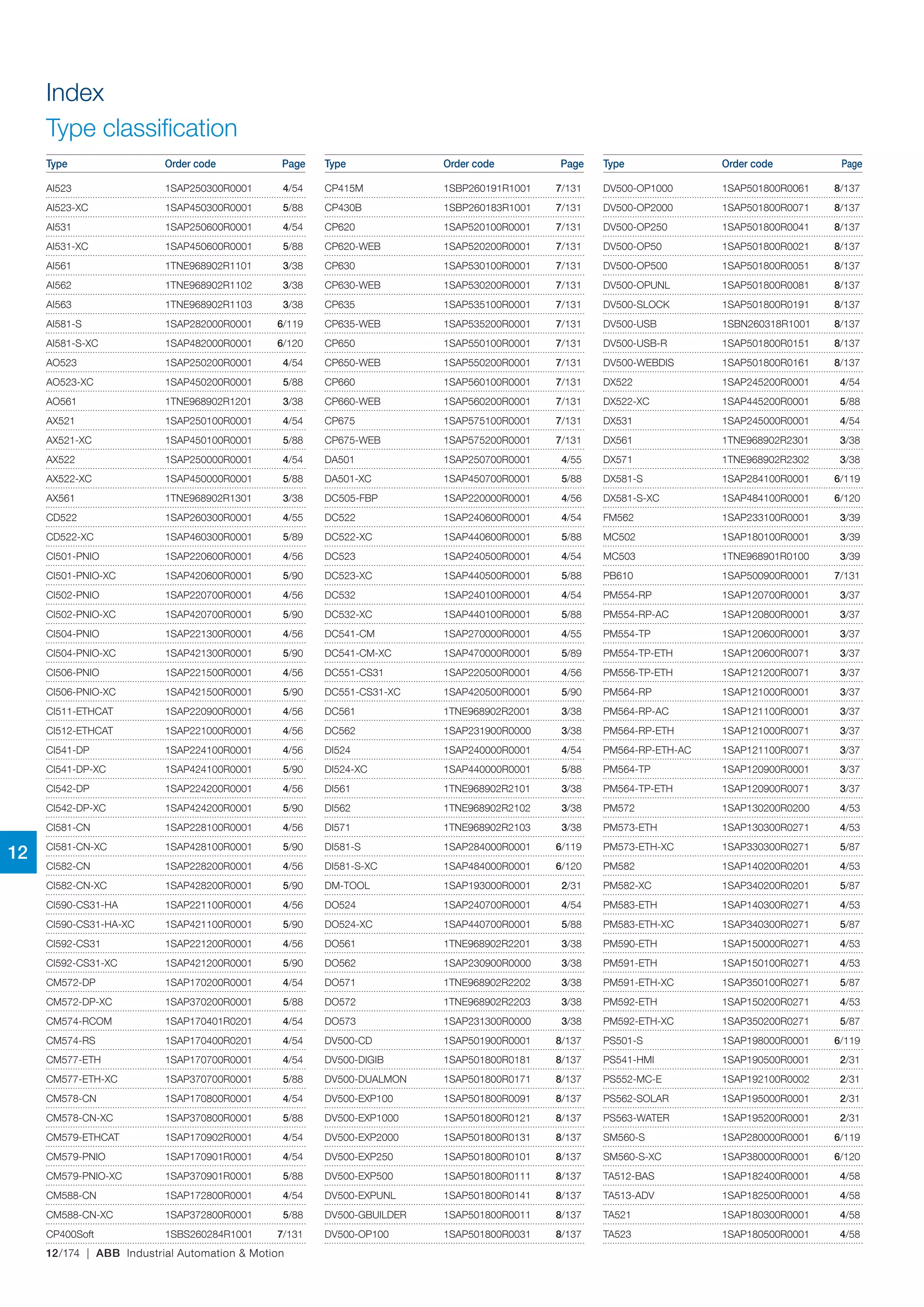
Industrial Automation & Motion
PLCs, HMIs, Drives, Servo Drives,
Motion Controllers
Main catalog
ABB Industrial Automation & Motion | 1/1
Industrial Automation & Motion
PLCs, HMIs, Drives, Servo Drives, Motion Controllers
AC500 products family
Automation Builder - Integrated engineering suite
AC500-eCo - Entry level PLC solutions
AC500 - High performance modular PLC
AC500-XC - PLC operating in eXtreme Conditions
AC500-S - Functional Safety PLC
CP600 and CP400 series - HMI and control panels
DigiVis 500 - Supervision software
Low voltage drives
Motion control
Application descriptions and additional information
Index
PLC-PHTC02U-EN - September 2014
1
2
3
4
5
6
7
8
9
10
11
12
1/2 | ABB Industrial Automation & Motion
AC500 products family
Overview
ABB offers a comprehensive range of scalable PLCs and robust HMI control panels as
well as high-availability solutions.
Since its launch in 2006, the AC500 PLC platform has achieved significant industry
recognition for delivering high performance, quality and reliability. ABB delivers
scalable, flexible and efficient ranges of automation components to fulfill all
conceivable automation applications.
Motor starter Motors Push buttons
Control panels
Flowmeter
DigiVis 500
Drives Temperature
probe
Softstarter
Example of connectivity options for AC500
Programming software inside
engineering suite
1
ABB Industrial Automation & Motion | 1/3
Programming software
Automation Builder integrates the
Engineering and Maintenance for
PLC, Drives, Motion, HMI and
Robotics.
It complies with the IEC 61131‑3
standard
offering all 5 IEC programming
languages for PLC and Drive con-
figuration. In addition, it includes
continuous function chart, C,
extensive function block libraries,
and powerful embedded simula-
tion/visualization features.
Automation Builder supports a
number of languages ( English,
German, French, Chinese, Span-
ish) and comes with new librar-
ies, FTP functions, SMTP, SNTP,
smart diagnostics and debugging
capabilities.
AC500
ABB's powerful flagship
PLC offering a wide range
of performance levels and
scalability within a single,
simple concept where most
competitors require multiple
product ranges to deliver
similar functionality. Web
server integrated and
IEC 60870-5-104 remote
control protocol for all
Ethernet versions.
Control panels
Our control panels offer a
wide range of touchscreen
graphical displays from 3.5"
up to 15". They are provided
with a user friendly configura-
tion software that enables
tailor made customized HMI
solutions. Rich sets of graphi-
cal symbols and the relevant
drivers for ABB automation
products are provided. Con-
trol panels for visualization of
AC500 webserver applica-
tions are available as well.
AC500-eCo
Meets the cost-effective
demands of the small PLC
market whilst offering total
inter-operability with the
core AC500 range. Up to
10 I/O modules connected
to the CPU, fast counter
onboard CPU up to 50 kHz.
Web server, FTP server and
Modbus-TCP for all Ethernet
versions. A Pulse Train Out-
put module is available for
multi axis positioning.
DigiVis 500
DigiVis 500 software is a
simple and easily accessible
solution in the development
of supervision applications. It
offers all the functions that are
essential to a secure environ-
ment, its functional reliability
and dual-display mode will
simplify all your supervision
operations, keeping interrup-
tions to a minimum.
AC500-XC
"Extreme conditions" modules
with extended operating tem-
perature, immunity to vibration
and hazardous gases, use at high
altitudes, in humid conditions,
etc.
It replaces advantageously
expensive cabinets by its built‑in
protection against dirt, water,
gases, dust.
AC500-S
A PLC based modular auto-
mation solution that makes it
easier than before to mix and
match standard and safety
I/O modules to expertly meet
your safety requirements in all
functional safety applications.
"Extreme conditions" version
is also offered.
Drives & Motion control
Our motion control products
and low voltage AC drives
include a choice of real-time
Ethernet and high-performance
multi‑axis motion control. A
broad selection of capabilities
includes communications
options, drive-based functional
safety features and program-
ming tools to adapt to a wide
range of applications.
1
1/4 | ABB Industrial Automation & Motion
AC500 products family
Automation Builder
Automation Builder is ABB's new engineering productivity suite for machine
builders and system integrators.
1
ABB Industrial Automation & Motion | 1/5
CP600
AC500
Automation Builder IEC 61131‑3
(IL, SFC, CFC, LD, FBD, ST)
ANSI C
AC500-S
Automation Builder IEC 61131‑3
(LD, FBD, ST)
ANSI C
ACS880
Automation Builder
IEC 61131‑3
(LD, FBD, IL, ST, SFC, CFC)
MicroFlex e150
MINT
IRB 7600
Automation Builder
Discover engineering productivity in engineering your
discrete automation solutions.
Automation Builder is ABB's integrated programming and
simulation environment for PLCs, safety, robots, motion,
drives and control panels.
Automation Builder integrates the proven ABB tools Control
Builder Plus, RobotStudio, Drive Manager, Mint WorkBench
and Panel Builder.
Minimize your efforts for managing your project code and
data with Automation Builder.
Improve your productivity through seamless engineering –
common data storage, single project archive, time saving
library blocks for device integration, and a common software
installer.
Reduce engineering effort and maintenance cost using easy
to use libraries for applications in wind, water, solar, drives,
motion, robotics and safety.
Benefit from the simplicity of IEC 61131-3, PLC open, ANSI C
and MINT programming languages.
Speed up your project by the bulk data handling capabilities
of Automation Builder.
Reduce downtime by simplified diagnostics and
maintenance.
Automation Builder is this single software suite for you to
configure and program various ABB controller families in a
single project.
Secure and restore your applications in a consistent joint
backup.
1
1/6 | ABB Industrial Automation & Motion
AC500 products family
At a glance…
The AC500 Programmable Logic Controllers offers the latest technology
enhancements with greater performance in a scalable package.
Standard industrial communications fieldbus, networks and
protocols supported by the 'One Platform' solution enable the
AC500 to be a very capable automation solution in demanding
environment. The flexible scalable range of superior perfor-
mance CPUs enables complete control of your application
whenever and wherever you need it.
Functionality
AC500-eCoAC500
CPUPerformance
PM554
PM564
PM554-ETH
PM564-ETH
PM592-ETH
PM556-ETH
PM572 PM573-ETH
PM582 SM560-S
Safety CPU
PM583-ETH
PM590-ETH
PM591-ETH
Ethernet enabled
Fieldbus enabled
Ethernet and Fieldbus enabled
eXtreme Conditions version available
PM554-ETHPM554 PM556-ETH
SM560-S
Ethernet
Fieldbus Ethernet and Fieldbus
1
ABB Industrial Automation & Motion | 1/7
AC500 products family
At a glance...
AC500-eCo AC500 AC500-XC AC500-S (2) AC500-S-XC (2)
System Configuration and Application programming  
Automation Builder (common programming tool)
Application Features
Extended temperature range
Functional safety
Support of simple motion with FM562 module (1)
Support of coordinated motion (1)
Support of High Availability (HA)
CPU Features AC500-eCo AC500 AC500-XC AC500-S (2) AC500-S-XC (2)
Performance (time per binary instruction) 0.08 µs 0.002...0.06 µs 0.002...0.06 µs 0.05 µs 0.05 µs
Program memory 128...512 kB 128...4096 kB 128...4096 kB 1024 kB 1024 kB
User data memory 14...130 kB 128...5632 kB 128...5632 kB 1024 kB 1024 kB
Remnent data (= saved) 2 kB 12...1536 kB 12...1536 kB 120 kB 120 kB
Serial communication
RS232
RS485
Isolated interface
Ethernet
DHCP, FTP server, Web server
Programming
Modbus-TCP
IEC 60870-5-104 remote control protocol
SNTP (Simple Network Time Protocol)
SMTP (Simple Mail Transfer Protocol)
Capability to connect Fieldbus Modules
I/Os integrated on CPU
I/O Modules Features S500-eCo S500 S500-XC S500-S (2) S500-S-XC (2)
Analog modules
Configurable
Dedicated
Digital modules
Configurable
Dedicated
Transistor outputs short circuit protected
Diagnosis for outputs
Extension with S500-eCo and S500(-XC) I/O modules (2) (2)
fully
partly
(1) Requires Library PS552-MC-E.
(2) AC500‑S and AC500‑S‑XC are extension CPU modules. They require an AC500 or AC500‑XC CPU to operate. The latter support all communication interfaces.
1
1/8 | ABB Industrial Automation & Motion
1
3
2
AC500-eCo Central Processing Unit (CPU)
– Different memory options
– Integrated communication option.
S500-eCo I/O Modules
– Up to 10 expansions
– Decentralized extension available.
1
2
Terminal blocks
– Three types of pluggable terminal blocks available.
3
AC500 products family
AC500-eCo
1
ABB Industrial Automation & Motion | 1/9
Terminal Base
– Same for all AC500 CPU types
– For 1, 2 or 4 communication modules
– With serial interfaces.
Communication Modules
– For PROFIBUS DP®
, Ethernet, Modbus TCP, EtherCAT®
CANopen®
or PROFINET®
IO
– Up to 4 pluggable.
AC500 Central Processing Unit (CPU)
– Different performance, memory, network, operating
conditions options
– Integrated communication.
1
3
2
1 32 45
S500 I/O Modules
– Up to 10 expansions
– Decentralized extension available.
Terminal units
– Up to 10 terminal units
– Decentralized extension available.
4
5
AC500 products family
AC500 and AC500-XC
1
1/10 | ABB Industrial Automation & Motion
AC500 products family
AC500-eCo system characteristics
AC500‑eCo CPUs can be locally expanded with up to 10 I/O modules.
New AC500‑eCo CPUs for use with pluggable terminal blocks available.
6
5
7
4
3
9
2
11
8
10
1
1
ABB Industrial Automation & Motion | 1/11
Adapter with realtime clock
AC500-eCo CPUs can
be locally expanded
with up to 10 I/O modules
(Standard S500 and S500-eCo
I/O modules can be mixed).
Wall mounting SD-card adapter
RS485 isolator for COM1 COM1 USB
COM2 USB
programming cable
1
2 SD-card
Adapter with COM2
& realtime clock
Adapter with COM2 Terminal blocks
3 4 5
6
7 8
9 10
11 AC500-eCo Starter kits. More information page 163.
1
1/12 | ABB Industrial Automation & Motion
3 764
AC500 products family
AC500 system characteristics
AC500, superior local extension capabilities for I/O communication and
best-in-class CPU functionality and industry leading performance.
82 5
9
1
1
ABB Industrial Automation & Motion | 1/13
1
CPU moduleCommunication module
Up to 4 modules in numerous
combinations to communicate
with nearly everything
Terminal base 432
S500-eCo I/O moduleS500 I/O moduleS500 Terminal unit5 6 7
BatterySD-card8 9
AC500 CPUs can be locally
expanded with up to 10 I/O
modules (Standard S500 and
S500-eCo I/O modules can be
mixed).
1
1/14 | ABB Industrial Automation & Motion
AC500 products family
Functional Safety
AC500‑S Safety PLC is the answer for complex machine safety applications that
need the highest level of reliability, efficiency and flexibility.
1
3
2
Hence this safety PLC is aimed at protecting people, machines
or processes, environment and investment. An ideal choice
of safety PLC that is well suited for wind turbine, crane, hoist
and robot applications.
1
ABB Industrial Automation & Motion | 1/15
More integration and easier programming
Featuring a consistent look and feel across the entire range,
the AC500 is the PLC of choice for applications where un-
compromising flexibility, integration and communication are
a must. With Automation Builder, you easily integrate your
safety application with your ABB PLC, Safety, Drives, Mo-
tion, HMI and Robotics. Automation Builder is simple to use
through the integrated standard languages like IEC 61131‑3,
letting you get up and running in no time at all. And not only
that: Clear configuration of the overall system with one single
tool ensures optimal transparency.
Safety CPU1 S500 Safety I/O module2 3 Safety terminal unit3
With the AC500-S Safety PLC, the latest addition to the
AC500 family, ABB takes the stress out of managing even the
most complex safety applications. Support for safety‑relevant
calculations such as COS, SIN, TAN, ASIN, ACOS and LOG
makes the AC500‑S ideal for applications in fields like crane
engineering, wind power generation, robotics and hoist tech-
nology. Plus it gives you greater flexibility and simplicity thanks
to safety programming under Structured Text (ST) as well as
full support for Function Block Diagram (FBD) and Ladder
Diagram (LD). Also available in extreme conditions version.
1
1/16 | ABB Industrial Automation & Motion
AC500 products family
Extreme conditions
PLC AC500‑XC for extreme conditions to be used indoor and outdoor.
Ruggedized variants of AC500 for those fighting with the elements.
Hence this PLC AC500-XC is aimed to be reliable, functional
and operational even under rough environmental conditions.
1 2
1
ABB Industrial Automation & Motion | 1/17
Operating in wet environment
– Increased resistance to 100 % humidity
with condensation.
Use at high altitudes
– Operating altitude up to 4000 m above
sea level.
Extended immunity to vibration
– 4 g root mean square random vibration
up to 500 Hz
– 2 g sinusoidal vibration up to 500 Hz.
Extended operating temperature
– -40 °C up to +70 °C operating temperature.
Extended immunity to hazardous gases and
salt mist
– G3, 3C2 immunity
– Salt mist EN 60068-2-52 / EN 60068-2-11.
Extended EMC requirements
– EN 61000-4-5 surge immunity test
– EN 61000-4-4 transient / burst immunity test.
Extreme conditions
S500 I/O module
4Extreme conditions CPU
and terminal base
Extreme conditions
communication module
1 2 3 Extreme conditions
S500 terminal unit
1
1/18 | ABB Industrial Automation & Motion
AC500 products family
AC500 libraries
The AC500 libraries increase stability, while reducing warranty and service efforts.
A good investment for System Integrators and end‑users. These library packages
contain easy to use examples enabling with minimal programming effort to realize
also complex and demanding applications quickly.
1
ABB Industrial Automation & Motion | 1/19
AC500 libraries especially focus on easy integration of drives,
HMI and supervisory systems, enabling your automation
solution to be built and commissioned quickly. AC500 solution
libraries by ABB are maintained to ensure that your programs
can also be used with less risk.
Motion control library
Library package for decentral, central and coordinated motion
following PLCopen®
standard.
Solar library
Library package for solar trackers to increase energy efficiency,
fast commissioning, excellent positioning accuracy.
Solar libraryMotion control library1 2 3 Water library
Water library
Library package with functions for energy efficiency and fast
commissioning of water applications for example pumping
stations and remote communications.
Drives integration library
Library package for fast integration of ABB ACS drives with
different field busses. Included free-of-charge in the Automa-
tion Builder suite.
1
1/20 | ABB Industrial Automation & Motion
AC500 products family
CP600 series
ABB control panels can be distinguished from their competitors by their easy yet
comprehensive functionality, making clear and easy to understand tailor made
operational information for production plants and machines available at a single
touch. CP600 control panels make machine operation efficient, predictable and
user-friendly.
1
ABB Industrial Automation & Motion | 1/21
CP600-WEB
with visualization for
AC500 web server
Automation Builder
programming station
Save engineering time by using Automation Builder for both your PLC and WebVisu
Connectivity with Drives directly without PLC
Build effective graphic interfaces with Panel Builder 600 - efficient representation of your information
CP600Automation Builder
programming station
AC500
without Webserver
AC500
with Webserver
Automation Builder
programming station
CP600 Drives
1
1/22 | ABB Industrial Automation & Motion
DigiVis 500 software is a simple and easily accessible solution in the development
of supervision applications.
Automation products
Supervision solution
Industrial Automation & Motion
It offers all the functions that are essential to a secure environ-
ment, its functional reliability and dual-display mode will simplify
all your supervision operations, keeping interruptions to a
minimum. Whether you are an OEM, a machine manufacturer
or an integrator, DigiVis 500 will adapt to any application,
machine or control room.
1
ABB Industrial Automation & Motion | 1/23
Create your applications quickly and easily
The environment and the development functions have been
designed to offer greater accessibility and to be exceptionally
user friendly. The management structure allows you to place
data in a hierarchy and access the different elements of your
project efficiently.
Configuring the supervision applications is easy, whether you
create your own or choose to customize or use one of the
predefined models from the different libraries.
Adaptability
A range of options is available to allow you to choose and adjust
the maximum number of operational variables per project.
Ranging from 50 to an infinite number of variable (OPC
signals), you will surely find a size to fit your application
needs.
Save time
DigiVis 500 is easy to connect and put into operation thanks
to its interaction with our PLC AC500 solution.
The development functions require no scripting, so you will
not waste time with debugging.
What is more, updating your projects on the fly allows you
to quickly make any minor changes without rebooting the
software.
Manage your projects efficiently
DigiVis 500 software runs on any Windows XP/7 PC platform.
The dual-display mode enhances availability.
The overview offers quick access to all available visualization
screens. The "DigiBrowse" option gives you access to all the
supervision data outside the software.
Manage your results
Data processing is optimized from archiving and safeguarding
to exporting and making practical use of the data.
Modularity
Whatever the size of your system, DigiVis 500 will suit your
needs. It will also allow you to manage High Availability sys-
tems with our turnkey PLC (CI590) supervision solution.
Reliability and security
The software's reliability and stability ensure a constant flow
in the supervision of installations and the recovery of key data,
particularly in managing high-availability solutions. The in-built
alarm system enables you to ensure the integrity of your
installations by customizing the advanced configuration.
The "Security lock" option, which controls access, allows you
to configure up to 16 profiles for a maximum of 1 000 individual
users.
1
1/24 | ABB Industrial Automation & Motion
ABB motion control drives offer flexible technologies and high performance motor
control to solve a wide variety of applications.
ABB motion control
Capability without complexity
1
ABB Industrial Automation & Motion | 1/25
Simple positioning CAMs,
Flying Shear,
registration
8 axes
Stepper / Analog
1- 5 axes intelligent
drives
>16 axes
Ethernet POWERLINK
Unified softwareMultiple hardware platformsScalable solutions
MINTTM
programmable motion systems
NextMove motion controllers offer high‑level machine
programming, multiaxis coordinated motion and a choice of
technologies form stepper control, analog control and real-time
Ethernet. Our intelligent drives are also programmable in the
same easy to use MINT language.
Flexible intelligent drives
MicroFlex e100 and MotiFlex e100 are programmable in MINT
Lite and provide solutions to simple motion tasks such as index-
ing. MINT lite also allows flexible solutions to distributed control
from PLCs where the behavior of each axis can be tailored to
simplify control schemes.
Motion control library
This library package for decentral, central and coordinated
motion enabling fast and standardized engineering, especially
together with ABB's motion control ACS Drives. The develop-
ment of this library according PLC Open Standard offers a future
proof investment.
Advanced intelligent drives
MicroFlex e150 supports multi‑tasking MINT programming with
additional support for software CAMs, flying shears
offering a single device solution to applications such as cut-to-
length and labelling. ACSM1 high power motion drives feature
SPC function block programming and a drive to drive (D2D) link
for synchronization of multiple axes,
Multi-axis intelligent drives
A plug‑in MINT motion controller option for MotiFlex e100
provides up to five axes of coordinated motion, eliminating the
need for an external controller. This high performance solution
utilizes Ethernet POWERLINK and reduces cabling and panel
space significantly offering a cost advantage.
1 to 5 axes
integrated
drive controller
For more than 25 years, MINT motion controls have been solving simple and complex motion tasks in the fields of
packaging, electronics assembly and test, simple CNC systems and many more. MINTTM
is a high level programming
language for simple multi-axis machine control. It combines multitasking efficiency, with event driven responsive-
ness and a simple plain english language to simplify machine and motion applications. MINT is supported by different
platforms, such as intelligent drives, panel-mount analog / stepper, real-time Ethernet motion controllers, and plug-in
controllers for drives, providing versatility in tackling a wide variety of applications.
Simple positioningSimple positioning
1
1/26 | ABB Industrial Automation & Motion
You base your business on cost efficiency and performance. We build advanced
drive technology that's capable and compatible with your needs, for today and
tomorrow. Our low voltage AC drives are flexible for you to optimize your process
control, and reliable for high availability. You also get premium service, responsible
solutions and expertise at your disposal, anywhere on the globe.
Low Voltage AC Drives
For premium motor control
You base your business on cost efficiency and performance.
We build advanced drive technology that's capable and
compatible with your needs, for today and tomorrow. Our low
voltage AC drives are flexible for you to optimize your process
control, and reliable for high availability. You also get premium
service, responsible solutions and expertise at your disposal,
anywhere on the globe.
1
ABB Industrial Automation & Motion | 1/27
ACS550
A wide power range for
a broad range of industries.
ACS310
Built-in features for pump
and fan applications.
ACS850
Flexibility and scalability for
machinery applications.
ACS355
Compact and easy drives to
install, set and commission.
ACSM1
The flexible workhorse for many
high performance applications.
ACS880-01
All-compatible wall-mounted drive
with everything built-in.
1
2/28 | ABB Industrial Automation & Motion
2
ABB Industrial Automation & Motion | 2/29
Automation Builder
Integrated engineering suite
Key features 2/30
Integrated engineering suite 2/31
Software features 2/32
Libraries features 2/33
2
2/30 | ABB Industrial Automation & Motion
Engineer your control and safety
functions using IEC 61131‑3
languages, CFC or ANSI C
Program and simulate your
robots application in Automation
Builder's RobotStudio
Seamlessly integrate and
optimize your drives and motion
configuration
Reduce downtime through
Automation Builder's powerful
debugging and diagnostics.
Configure high performance
control panel applications
Automation Builder
Key features
2
ABB Industrial Automation & Motion | 2/31
Automation Builder
Integrated engineering suite
Automation Builder
Automation Builder Engineering Suite
– For all AC500 CPUs, all programming languages including Continuous Function Chart according to
IEC 61131‑3
– Contains: 6 programming languages, sampling trace, debugging, offline simulation, integrated
visualization, trace recording (multi-channel), recipe management
– Languages: French, English, German, Chinese, Spanish
Scope of delivery: software, libraries and documentation on USB ROM
– Single seat license
– GCC included, Wind River Diab compiler can be integrated by user.
For Description Type Order code Price Weight
(1 pce)
kg
all AC500 CPUs Automation Builder Engineering Suite DM-TOOL 1SAP193000R0001 0.400
License for runtime visualization package.
For installation and visualization of images created with
the Automation Builder Engineering Suite (2)
PS541-HMI (1) 1SAP190500R0001 0.300
(1) This package allows granting the license for the software. To install the HMI software, Automation Builder must be purchased
separately.
(2) Delivery includes license code and documentation.
Libraries
For Description Type Order code Price Weight
(1 pce)
kg
all AC500 CPUs Solar library (3) PS562-SOLAR 1SAP195000R0001 0.300
all AC500 CPUs Water library (3) PS563-WATER 1SAP195200R0001 0.300
all AC500 CPUs Motion Control library, Extended (3) PS552-MC-E 1SAP192100R0002 0.300
(3) Delivery on USB stick that includes: library, single license code and documentation.
Further application libraries and examples:
Please check and download further libraries and examples from: www.abb.com/plc
Use English language setting, then click on "Applications Libraries" or "Applications Examples".
– Applications Libraries add further functionality to AC500 PLC's. They are well tested library packages with
application example(s) and documentation, have limited support and are free of charge.
- FTP-Client, HVAC, ...
– Applications Examples explain functionality by using e.g. standard Automation Builder libraries and func-
tions in examples.
They are tested in the described example configuration and functionality and also come with documenta-
tion and are free of charge.
- KNX, MySQL, Fieldbuses, device connections and many others.
Applications Libraries and Examples help to minimize valuable programming and testing time for specific
applications.
Solar library
Motion control library
Water library
2
2/32 | ABB Industrial Automation & Motion
Automation Builder
Software features
Technical data Automation Builder
Description Engineering Suite. Contains configuration and programming tool for AC500-based automation
systems, based on CODESYS Automation Platform technology.
Features – Common software installer
– PLC configuration and programming
– All 5 IEC 61131-5 languages IL, LD, FBD, SFC, ST, plus CFC
– Extensive PLC programming libraries
– I/O and communication module setup
– Protocol settings (UDP, TCP, FTP, SNTP, SMTP, HTTP, PING, Modbus TCP, IEC 60870-5-104)
– Network device scan: scan function and IP configurator
– PLC firmware update, download and online change to single or several PLCs
– Recipe management
– PLC simulation and debugging
– Online diagnostics
– Multiple watch lists
– Drive Manager – remote drive configuration and diagnostics via PLC tunneling on PROFINET®
or PROFIBUS®
connection
– CP600 project and Pluto safety data in same project file
– CODESYS visualization for PC
– Various language support.
Minimum engineering PC requirements Windows XP SP3, Windows 7 SP1 32 or 64‑bit, 1 GHz, 3 GB RAM, 10 GB free disk space.
Target Systems – PLC AC500-eCo, AC500, AC500-XC, AC500-S (1), ACS880 (2)
– Control Panel CP600
– Robot Controller IRC5
– Mint motion controllers.
Supported Devices on PLC fieldbus – All I/O and fieldbus modules for AC500 family
– PROFINET®
/Profibus®
drives ACS355, ACQ810, ACS850, ACS880, ACSM1, MicroFlex e150,
IRC5 with PROFINET®
slave
Included components – Control Builder Plus
– PS553-DRIVES drive library
– Drive Manager plug-in
– Panel Builder 600
– RobotStudio (Basic license)
– Mint WorkBench
– CODESYS tools (OPC server and clients, service tool, PLC gateway, IP configuration)
– GNU compiler, C programming (3).
Additional options – PS501-S safety library
– PS541-HMI visualization
– PS552-MC-E PLCopen®
motion library
– RobotStudio Premium license
– ACS880 IEC application programming.
Comments (1) requires PS501-S safety library.
(2) requires ACS880 IEC application programming option.
(3) for AC500 and AC500-XC targets.
2
ABB Industrial Automation & Motion | 2/33
PS552-MC-E PS562-SOLAR PS563-WATER
Motion control library Solar tracker solution library Water solution library
Library enabling fast and standardized
engineering according to PLCopen®
standard
when using ABB's AC500 PLC for motion
control, especially together with ABB's motion
control Drives.
Covers different motion control options for single
and multiaxis motion control applications:
– Drive-Based and PLC-Based motion
– In PLC based motion, the position control
loop could be closed in the PLC or drive (with
synchronized network)
– Single axis, multiaxis and coordinated
motion
– Defined Jerk limitation by polynomial
interpolation
– Spline interpolation or polynomial interpolation
for cam curves, position velocity or accelera-
tion profiles available
– Possible to switch over between different
movements and cam curves directly
– latch functionality by utilizing fast drive inputs
for ACS350, ACS800, ACSM1
– Drive based motion: commands from PLC,
drives perform interpolation and control loop
– Supports the new Pulse Train Output module
FM562.
PLCopen®
functions:
– Administrative Function Blocks
– Single axis Function Blocks
– Multiple axis Function Blocks
– Homing Function Blocks
– Coordinated Motion Function Blocks
– Additional ABB specific Function Blocks for
further simplification.
Library for solar tracking applications enabling
fast engineering, especially together with
ABB's drives and motors
Covers different tracker configurations and
different algorithms for accuracy needs
– Control of trackers in parabolic trough,
power tower, PV and CPV applications.
Complete library package for different tracking
use cases, plug and play:
Example program with detailed explanations
and visualizations
– Control of the tracker adaptable to different
needs and conditions, to achieve maximum
efficiency of installation
– Exact positioning of different axes with the
following accuracies:
- NOAA algorithm 0.03 Grad
- NREL algorithm 0.0003 Grad.
– Input / sensor adaptation
– Communication
– Different actuators / drives control
– All needed modes for simple commissioning
and manual operation:
- Fast and simple calibration of the trackers,
offering manual repositioning and fine tuning
- Safety positions
- Back tracking.
Library supporting the most common functions
in many water applications
Flexible data logging options:
– Especially suited for remote communication
like GSM/GPRS
– Timestamp in logging
– Integrated variants for simple use with
IEC 60870
– Logging to files: storage capacity only de-
pendent on memory availability
– Flexible log conditions (cyclic, event or
tolerance based).
Support for pumping station functions with dif-
ferent operation modes
– Standard multidrive functions (PLC based)
– Advanced functionality together with ABB
ACS and ACQ810 drives
– Detailed diagnosis
– Energy efficiency functions
– Multidrive functions
– Flow estimation.
CP600 support for ACQ810: Fast and simple
configuration for pumping stations with re-
duced programming effort via pre-built
visualization screen templates.
Application examples for fast engineering and
startup.
Package with self installing software and license
code on USB‑stick.
Package with self installing
software and license code on USB‑stick.
Package with self installing software and
license code on USB‑stick.
All AC500 CPUs (options and no. of blocks/
functions and performance will depend on CPU
size and memory).
NOAA: PM554-XX and above
NREL: PM573-ETH and above.
All AC500 CPUs.
Logging: PM573 and above.
2
3/34 | ABB Industrial Automation & Motion
3
ABB Industrial Automation & Motion | 3/35
AC500-eCo
Entry level PLC solutions
Key features 3/36
Entry level PLC solutions 3/37
Technical data 3/40
System data 3/47
3
3/36 | ABB Industrial Automation & Motion
AC500-eCo
Key features
– Up to 10 I/O modules
connected to the CPU
– Compatible with all standard
I/O modules (S500 and
S500-eCo)
– Digital I/O module with
configurable I/O available
High performance with large
memory variant available
Comprehensive communication
options:
– Ethernet for communication
and Web server for user
defined visualization
– Up to two serial ports
for decentralized I/O and
communication
– Three different types of terminal
blocks available
– Integrated onboard I/O
– AC versions with integrated
power supply
3
ABB Industrial Automation & Motion | 3/37
AC500-eCo CPUs
– 1 RS485 serial interface (2nd is optional)
– Centrally expandable with up to 10 I/O modules
(standard S500 and/or S500‑eCo modules can be mixed)
– Optional SD card adapter for data storage and program backup
– Variants with integrated Ethernet (Ethernet includes web server)
– Minimum cycle time per instruction: Bit 0.08 µs, Word 0.1 µs, Float-point 1.2 µs.
– Relays up to 2A each or 6A per group (total current) at 120/240 VAC or 24 VDC
Program
memory
Onboard
I/Os
Relay /
Transistor
outputs
Integrated
communication
Power
supply
Type Order code Price Weight
(1 pce)
kB DI/DO/AI/AO kg
PM554: digital I/Os
128 8 / 6 / – / – Transistor – 24 V DC PM554-TP 1SAP120600R0001 0.300
128 8 / 6 / – / – Relay – 24 V DC PM554-RP 1SAP120700R0001 0.400
128 8 / 6 / – / – Relay – 100-240 V AC PM554-RP-AC 1SAP120800R0001 0.400
128 8 / 6 / – / – Transistor Ethernet 24 V DC PM554-TP-ETH 1SAP120600R0071 0.400
PM556: digital I/Os, 512 kB program memory
512 8 / 6 / – / – Transistor Ethernet 24 V DC PM556-TP-ETH 1SAP121200R0071 0.400
PM564: digital and analog I/Os (1)
128 6 / 6 / 2 / 1 Transistor – 24 V DC PM564-TP 1SAP120900R0001 0.300
128 6 / 6 / 2 / 1 Relay – 24 V DC PM564-RP 1SAP121000R0001 0.400
128 6 / 6 / 2 / 1 Relay – 100-240 V AC PM564-RP-AC 1SAP121100R0001 0.400
128 6 / 6 / 2 / 1 Transistor Ethernet 24 V DC PM564-TP-ETH 1SAP120900R0071 0.300
128 6 / 6 / 2 / 1 Relay Ethernet 24 V DC PM564-RP-ETH 1SAP121000R0071 0.400
128 6 / 6 / 2 / 1 Relay Ethernet 100-240 V AC PM564-RP-ETH-AC 1SAP121100R0071 0.400
Terminal blocks (9 or 11 poles) are necessary for each AC500‑eCo I/O. They are delivered separately.
(1) All analog inputs on PM564 can be configured as digital inputs. Analog inputs are 0‑10VDC only. 1 Analog output configurable as
0-10 VDC, 0-20mA, or 4-20mA
AC500-eCo
Entry level PLC solutions
PM554
PM556
PM564
3
3/38 | ABB Industrial Automation & Motion
AC500-eCo
Entry level PLC solutions
S500-eCo I/O modules
– For central expansion of the AC500 or AC500‑eCo CPUs
– For decentralized expansion in combination with communication interface module DC551‑CS31,
PROFINET®
CI50x modules, CI592‑CS31, PROFIBUS®
modules CI54x, and CANopen®
modules CI58x
(not usable with DC505-FBP module and CI590-CS31-HA).
Digital I/O
– DC: Channels can be configured individually as inputs or outputs.
Number of Input signal Output
type
Output signal Terminal block
required
Type Order code Price Weight
(1 pce)
DI/DO/DC 9 poles 11 poles kg
8 / – / – 24 V DC – – 1 – DI561 1TNE968902R2101 0.12
16 / – / – 24 V DC – – 1 1 DI562 1TNE968902R2102 0.12
8 / – / – 100-240 V AC – – 1 1 DI571 1TNE968902R2103 0.15
– / 8 / – – Transistor 24 V DC, 0.5 A – 1 DO561 1TNE968902R2201 0.12
– / 16 / – – Transistor 24 V DC, 0.5 A 1 1 DO562 1SAP230900R0000 0.16
– / 8 / – – Relay 24 V DC, 120 /
240 V AC, 2 A
– 1 DO571 1TNE968902R2202 0.15
– / 8 / – – Triac 100-240 V AC, 0.3 A 1 1 DO572 1TNE968902R2203 0.12
– / 16 / – – Relay 24 V DC, 120 /
240 V AC, 2 A
1 1 DO573 1SAP231300R0000 0.19
8 / 8/ – 24 V DC Transistor 24 V DC, 0.5 A 1 1 DX561 1TNE968902R2301 0.12
8 / 8/ – 24 V DC Relay 24 V DC, 120 /
240 V AC, 2 A
1 1 DX571 1TNE968902R2302 0.15
– / – / 16 24 V DC Transistor 24 V DC, 0.1A HE10-20 – DC561 1TNE968902R2001 0.12
– / – / 16 24 V DC Transistor 24 V DC, 0.5 A 1 1 DC562 1SAP231900R0000 0.15
Terminal blocks (9 or 11 poles) are necessary for each S500‑eCo I/O. They are delivered separately.
Analog I/O
– Each channel can be configured individually
– Resolution:
- AI561, AO561, AX561: 12 bits/11 bits + sign
- AI562, AI563: 15 bits + sign.
Number of Input signal Output signal Terminal block
required
Type Order code Price Weight
(1 pce)
AI/AO 9 poles 11 poles kg
4 / 0 ±2.5 V, ±5 V, 0...5 V,
0...10 V, 0...20 mA,
4...20 mA
– 1 1 AI561 1TNE968902R1101 0.12
2 / 0 PT100, PT1000, Ni100,
Ni1000, Resistance:
150 Ω, 300 Ω
– – 1 AI562 1TNE968902R1102 0.12
4 / 0 S, T, R, E, N, K, J,
Voltage range: ±80 mV
– 1 1 AI563 1TNE968902R1103 0.12
0 / 2 – ‑10...+10 V, 0...20 mA,
4...20 mA
– 1 AO561 1TNE968902R1201 0.12
4 / 2 ±2.5 V, ±5 V, 0...5 V,
0...10 V, 0...20 mA,
4...20 mA
‑10...+10 V, 0...20 mA,
4...20 mA
1 1 AX561 1TNE968902R1301 0.13
Terminal blocks (9 or 11 poles) are necessary for each S500‑eCo I/O. They are delivered separately.
DI561
AI562
AX561
3
ABB Industrial Automation & Motion | 3/39
AC500-eCo
Entry level PLC solutions
Positioning module
– For central expansion of the AC500 or AC500‑eCo CPUs
– For decentralized expansion in combination with communication interface modules CI58X‑CN,
CI50X-PNIO or CI54X-DP
– Not for use in combination with communication interface modules DC551-CS31, DC505-FBP, CI51X
or CI59X
– The FM562 module provides Pulse Train Outputs for 2 axes. Profile generator integrated.
Number
of axis
Input signal Output signal Terminal block
required
Type Order code Price Weight
(1 pce)
9 poles 11 poles kg
2 4 digital inputs 24 V
(2 per axis)
4 pulse outputs
RS422 (2 per axis)
1 1 FM562 1SAP233100R0001 0.15
Terminal blocks (9 or 11 poles) are necessary for each S500‑eCo I/O. They are delivered separately.
Library PS552-MC-E is required for programming this module.
Accessories
Description Type Order code Price Weight
(1 pce)
kg
SD Memory Card 2 GB needs the MC503 option MC502 1SAP180100R0001 0.020
SD Memory Card adapter MC503 1TNE968901R0100 0.010
Programming cable USB => RS485 Sub-D, 3 m TK503 1TNE968901R1100 0.400
Programming cable USB => RS485 Terminal block, 3 m TK504 1TNE968901R2100 0.400
RS485 isolator, Sub-D 9 poles / Terminal 5 poles for COM1 TK506 1SAP186100R0001 0.080
Real time clock option board, battery CR2032 not included TA561-RTC (1) 1SAP181400R0001 0.007
RS485 serial adapter COM2, pluggable screw terminal block included TA562-RS 1TNE968901R4300 0.007
Combined Real Time Clock option with RS485 serial
adapter COM2, pluggable screw terminal block, included
TA562-RS-RTC (1) 1SAP181500R0001 0.012
Wall Mounting Accessory for AC500-eCo CPU and S500-eCo
I/O modules (100 pieces per case)
TA566 1TNE968901R3107 0.450
Set of accessories: 6 x plastic cover for option slot,
6 x 5 pole terminal block, 6 x 5 pole screw terminal block
for COM2 serial interface.
TA570 1TNE968901R3203 0.090
Digital input simulator for onboard I/O of CPU, 6 x switch, 24 V DC TA571-SIM 1TNE968903R0203 0.040
(1) Standard battery CR 2032 has to be purchased separately.
Terminal blocks for S500-eCo I/O modules and AC500-eCo CPUs
Number of
poles
Connection type Cable entry Type Order code Price Weight
(1 pce)
kg
9 Screw Side TA563-9 1TNE968901R3101 0.017
11 Screw Side TA563-11 1TNE968901R3102 0.020
9 Screw Front TA564-9 1TNE968901R3103 0.026
11 Screw Front TA564-11 1TNE968901R3104 0.035
9 Spring Front TA565-9 1TNE968901R3105 0.016
11 Spring Front TA565-11 1TNE968901R3106 0.020
Only ABB terminal blocks must be used with AC500‑eCo.
TA562-RS-RTC
TA562-RS
TA561-RTC
TA570
FM562
TA565-9
TA564-11
TK506
TA563-9
3
3/40 | ABB Industrial Automation & Motion
AC500-eCo CPUs
Type PM554-TP PM554-RP PM554-RP-AC PM554-TP-ETH PM556-TP-ETH
Supply voltage 24 V DC 100-240 V AC 24 V DC
Current consumption on 24 V DC 100 V AC 240 V AC 24 V DC
AC500-eCo
Technical data
Min. typ. (module alone) 0.06 A 0.08 A 0.02 A 0.012 A 0.07 A 0.07 A
Max. typ. (I/Os) 0.18 A 0.22 A 0.2 A 0.11 A 0.19 A 0.19 A
Program memory 128 kB 512 kB
Integrated data memory 14 kB thereof 2 kB saved 130 kB thereof 2 kB saved
Web server's data for user RAM disk – 512 kB 1024 kB
Data buffering (of saved data) flash memory
Real-time clock (option with battery back-up) (1) 
Program execution
Cyclical 
Time controlled 
Multi tasking no, 1 task + 1 interrupt task max.
Interruption 
User program protection by password 
Cycle time for 1 instruction (minimum)
Binary 0.08 µs
Word 0.1 µs
Floating 1.2 µs
Onboard digital inputs
Channels 8
Signal voltage 24 V DC
Onboard digital outputs
Channels 6
Relay / Transistor Transistor Relay Relay Relay Transistor Transistor
Rated voltage 24 V DC 240 V AC 240 V AC 240 V AC 24 V DC 24 V DC
Nominal current per channel 0.5 A 2 A resistive 2 A resistive 2 A resistive 0.5 A 0.5 A
Onboard analog inputs
Channels -
signal ranges -
Onboard analog outputs
Channels -
signal ranges -
Max. number of centralized inputs/outputs
Max. number of extension modules on I/O bus up to max. 10 (S500 and/or S500‑eCo modules allowed)
Digital inputs 320 + 8
outputs 320 + 6
Analog inputs 160
outputs 160
Max. number of decentralized inputs/outputs
I/O modules decentralized on CS31 bus: up to 31 stations with up to 120 DI / 120 DO each or up to 32 AI/32 AO per station
Internal interfaces
COM1
RS485 
Sub-D connection 
Programming, Modbus, ASCII, CS31 
COM2 (option) (2)
RS485 
Terminal block 
Programming, Modbus, ASCII 
Ethernet
RJ45 – 
Ethernet functions:
Programming, Modbus TCP/IP, UDP/IP, integrated
Web server, DHCP, FTP server
– 
RUN/STOP switch 
LED display for power, status and error 
Approvals see detailed overview page 166 or www.abb.com/plc
(1) Real‑time clock requires optional TA561‑RTC or TA562‑RS‑RTC.
(2) COM2 requires TA562-RS-RTC or TA562-RS.
3
ABB Industrial Automation & Motion | 3/41
AC500-eCo CPUs
Type PM564-TP PM564-RP PM564-RP-AC PM564-TP-ETH PM564-RP-ETH PM564-RP-ETH-AC
Supply voltage 24 V DC 100-240 V AC 24 V DC 100-240 V AC
Current consumption on 24 V DC 100 V AC 240 V AC 24 V DC 100 V AC 240 V AC
AC500-eCo
Technical data
Min. typ. (module alone) 0.095 A 0.11 A 0.02 A 0.011 A 0.10 A 0.12 A 0.023 A 0.014 A
Max. typ. (I/Os) 0.21 A 0.24 A 0.21 A 0.125 A 0.22 A 0.25 A 0.22 A 0.13 A
Program memory 128 kB
Integrated data memory 14 kB thereof 2 kB saved
Web server's data for user RAM disk – 512 kB
Data buffering (of saved data) flash memory
Real-time clock (option with battery back-up) (1) 
Program execution
Cyclical 
Time controlled 
Multi tasking no, 1 task + 1 interrupt task max.
Interruption 
User program protection by password 
Cycle time for 1 instruction (minimum)
Binary 0.08 µs
Word 0.1 µs
Floating 1.2 µs
Onboard digital inputs
Channels 6
Signal voltage 24 V DC
Onboard digital outputs
Channels 6
Relay / Transistor Transistor Relay Relay Transistor Relay Relay
Rated voltage 24 V DC 240 V AC 240 V AC 24 V DC 240 V AC 240 V AC
Nominal current per channel 0.5 A 2 A resistive 2 A resistive 0.5 A 2 A resistive 2 A resistive
Onboard analog inputs
Channels 2
signal ranges 0...10 V / can be configured as digital input 24 V DC
Onboard analog outputs
Channels 1
signal ranges 0...10 V / 0...20 mA / 4...20 mA
Max. number of centralized inputs/outputs
Max. number of extension modules on I/O bus up to max. 10 (S500 and/or S500‑eCo modules allowed)
Digital inputs 320 + 8
outputs 320 + 6
Analog inputs 160 + 2
outputs 160 + 1
Max. number of decentralized inputs/outputs
I/O modules decentralized on CS31 bus: up to 31 stations with up to 120 DI / 120 DO each or up to 32 AI/32 AO per station
Internal interfaces
COM1
RS485 
Sub-D connection 
Programming, Modbus, ASCII, CS31 
COM2 (option) (2)
RS485 
Terminal block 
Programming, Modbus, ASCII 
Ethernet
RJ45 – 
Ethernet functions:
Programming, Modbus TCP/IP, UDP/IP, integrated
Web, DHCP, FTP
– 
RUN/STOP switch 
LED display for power, status and error 
Approvals see detailed overview page 166 or www.abb.com/plc
(1) Real‑time clock requires optional TA561‑RTC or TA562‑RS‑RTC.
(2) COM2 requires TA562-RS-RTC or TA562-RS.
3
3/42 | ABB Industrial Automation & Motion
AC500-eCo
Technical data
Digital S500-eCo I/O modules
Type DI561 DI562 DI571 DO561 DO562
Supply voltage – – – 24 V DC 24 V DC
Current consumption on UP
Max. typ. (without load current) – – – 0.005 A 0.005 A
Number of channels per module
Digital inputs 8 16 8 (AC) – –
outputs – – – 8 16
Configurable as Input or Output DC – – – – –
Relay / Transistor – – – Transistor Transistor
Additional configuration of channels as:
Fast Counter no not applicable
Digital inputs
Input signal voltage 24 V DC 110-240 V AC – –
Input time delay typically 4...8 ms typically 15 ms / 30 ms – –
Input current per channel
At Input voltage 24 V DC typically 5 mA – – –
5 V DC typically 1 mA – – –
15 V DC > 2.5 mA – – –
30 V DC < 8 mA – – –
40 V AC – < 3 mA – –
159 V AC – > 6 mA – –
Output current
Nominal current per channel – – – 0.5 A at UP = 24 V
Maximum (total current of all channels) – – – 4 A 8 A
Residual current at signal state 0 – – – < 0.5 mA
Demagnetization when switching off
inductive loads
– – – must be provided externally
Switching frequency
For resistive load – – – limited by CPU cycle time
For inductive load – – – max. 0.5 Hz
For lamp load – – – max. 11 Hz at max. 5 W
Short circuit / overload proofness – – – no
Overload indication (I > 0.7 A) – – – no
Output current limiting – – – no
Proofness against reverse feeding of 24 V signals – – – no
Contact rating
For resistive load, max. – – – –
For inductive load, max. – – – –
For lamp load – – – –
Lifetime (switching cycles)
Mechanical lifetime – – – –
Lifetime under load – – – –
Maximum cable length for connected process signals
Cable shielded 500 m
unshielded 300 m 150 m
Potential isolation
Per module    
Between the channels input – per group of 8  –
output – – – – –
Voltage supply for the module's logic internal via I/O bus
Fieldbus connection
Suitable communication interface module CI501-PNIO, CI502-PNIO, CI504-PNIO, CI506-PNIO, CI541-DP, CI542-DP, CI581-CN, CI582-CN, DC551-CS31,
CI592-CS31
3
ABB Industrial Automation & Motion | 3/43
AC500-eCo
Technical data
Digital S500-eCo I/O modules
Type DO571 DO572 DO573
Supply voltage 24 V DC
Current consumption on UP
Max. typ. (without load current) 0.050 A – 0.050 A
Number of channels per module
Digital inputs – – –
outputs 8 8 16
Configurable as Input or Output DC – – –
Relay / Transistor Relay triac (AC) Relay
Process voltage
DC 24 V – –
Digital inputs
Input signal voltage – – –
Input time delay – – –
Input current per channel
At Input voltage 24 V DC – – –
5 V DC – – –
15 V DC – – –
30 V DC – – –
Output current
Nominal current per channel 2 A (24 V DC / 120 V AC /
240 V AC, resistive load)
0.3 A at
100...240 V AC
2 A (24 V DC / 120 V AC /
240 V AC, resistive load)
Maximum (total current of all channels) 2 x 8 A 2.4 A / 8 x 0.3 A max 10 A per group
(20 A per module)
Residual current at signal state 0 – 1.1 mA rms at 132 V AC and
1.8 mA rms at 264 V AC
–
Demagnetization when switching off
inductive loads
must be performed externally
Switching frequency
For resistive load 1 Hz max. 10 Hz max. 1 Hz max.
For inductive load – – –
For lamp load 1 Hz max. 10 Hz max. 1 Hz max.
Short circuit / overload proofness no
Overload indication (I > 0.7 A) no
Output current limiting no
Proofness against reverse feeding of 24 V signals yes – yes
Contact rating
For resistive load, max. 2 A 0.3 A 2 A
For inductive load, max. – – –
For lamp load 200 W at 230 V AC
30 W at 24 V DC
– 200 W at 230 V AC
30 W at 24 V DC
Lifetime (switching cycles)
Mechanical lifetime 100 000 – 100 000
Lifetime under load 100 000 at rated load – 100 000 at rated load
Maximum cable length for connected process signals
Cable shielded 500 m
unshielded 150 m
Potential isolation
Per module between outputs and logic  between outputs and logic
Between the channels input – – –
output per group of 4  per group of 8
Voltage supply for the module's logic internal via I/O bus
Fieldbus connection
Suitable communication interface module CI501-PNIO, CI502-PNIO, CI504-PNIO, CI506-PNIO, CI541-DP, CI542-DP, CI581-CN, CI582-CN, DC551-CS31,
CI592-CS31
3
3/44 | ABB Industrial Automation & Motion
AC500-eCo
Technical data
Digital S500-eCo I/O modules
Type DX561 DX571 DC561 DC562
Supply voltage 24 V DC
Current consumption on UP
Max. typ. (without load current) 0.005 A 0.050 A 0.010 A 0.010 A
Number of channels per module
Digital inputs 8 8 – –
outputs 8 8 – –
Configurable as Input or Output DC – – 16 16
Relays / Transistor Transistor Relay Transistor Transistor
Process voltage
DC 24 V 24 V 24 V 24 V
Digital inputs
Input signal voltage 24 V DC 24 V DC 24 V DC 24 V DC
Input time delay typically 4...8 ms typically 8 ms
Input current per channel
At Input voltage 24 V DC typically 5 mA typically 5 mA typically 4 mA typically 5 mA
5 V DC < 1 mA < 1 mA < 1 mA typically 1 mA
15 V DC > 2.5 mA > 2.5 mA > 2.5 mA > 2.5 mA
30 V DC < 6.5 mA < 6.5 mA < 6 mA < 8 mA
Output current
Nominal current per channel 0.5 A at UP = 24 V DC 2 A (24 V DC / 120 V AC /
240 V AC, resistive load)
0.1 A at UP = 24 V DC 0.5 A at UP = 24 V DC
Maximum (total current of all channels) 4 A 2 x 8 A 1.6 A 8 A
Residual current at signal state 0 < 0.5 mA – < 0.5 mA < 0.5 mA
Demagnetization when switching off
inductive loads
must be performed externally
Switching frequency
For resistive load Limited by CPU cycle time 1Hz max. Limited by CPU cycle time
For inductive load 0.5 Hz max. – 0.5 Hz max. 0.5 Hz max.
For lamp load 11 Hz max. at max. 5 W 1 Hz max. – 11 Hz max. at max. 5 W
Short circuit / overload proofness no
Overload indication (I > 0.7 A) no
Output current limiting no
Proofness against reverse feeding of 24 V signals no yes no no
Contact rating
For resistive load, max. – 2 A – –
For inductive load, max. – – – –
For lamp load – 200 W at 230 V AC
30 W at 24 V DC
– –
Lifetime (switching cycles)
Mechanical lifetime – 100 000 – –
Lifetime under load – 100 000 at rated load – –
Maximum cable length for connected process signals
Cable shielded 500 m
unshielded 150 m
Potential isolation
Per module  –  
Between the channels input – – – –
output – per group of 4 – –
Voltage supply for the module's logic internal via I/O bus
Fieldbus connection
Suitable communication interface module CI501-PNIO, CI502-PNIO, CI504-PNIO, CI506-PNIO, CI541-DP, CI542-DP, CI581-CN, CI582-CN, DC551-CS31,
CI592-CS31
3
ABB Industrial Automation & Motion | 3/45
AC500-eCo
Technical data
Analog S500-eCo I/O modules
Type AI561 AO561 AX561 AI562 AI563
Supply voltage 24 V DC
Current consumption on UP
Max. typ. (without load current) 0.100 A 0.100 A 0.140 A 0.040 A 0.100 A
Number of channels per module
Analog inputs 4 – 4 2 4
outputs – 2 2 – –
Inputs, individually configurable
-2.5…+2.5 V 11 bits + sign  –  – –
-5…+5 V 11 bits + sign  –  – –
-10…+10 V 11 bits + sign – – – – –
0…5 V 12 bits  –  – –
0…10 V 12 bits  –  – –
0…20 mA, 4…20 mA 12 bits  –  – –
RTD – – – 2 –
Pt100
-50…+400 °C (2/3- wire) – – –  –
Pt1000
-50…+400 °C (2/3-wire) – – –  –
Ni100 / Ni1000
-50…+150 °C (2/3-wire) – – –  –
Resistor 0…150 Ω/0...300 Ω – – –  –
Thermocouple Types J, K, T, N, S, E, R – – – – 
Voltage -80...+80 mV – – – – 
Outputs, individually configurable
-10...+10 V –   – –
0…20 mA –   – –
4…20 mA –   – –
Potential isolation
Per module – – –  
Fieldbus connection
Suitable communication interface module CI501-PNIO, CI502-PNIO, CI504-PNIO, CI506-PNIO, CI541-DP, CI542-DP, CI581-CN, CI582-CN, DC551-CS31,
CI592-CS31
3
3/46 | ABB Industrial Automation & Motion
AC500-eCo
Technical data
FM562 positioning module
The FM562 module contains Pulse Train Outputs for 2 axes. Profile generator for simple motion control tasks are integrated. The RS422 outputs
allow a direct connection to Stepper‑ or Servo drives. Function blocks in PLCopen®
motion control style allow the integration of the module in an
application. These function blocks are contained in the library PS552‑MC‑E.
Type FM562
Functionality
Number of axis 2
Digital inputs 2 digital inputs per axis
Function: for axis enable or limit switch
Pulse outputs Modes cw/ccw or pulse/direction
Built in profile generators
Data of the digital inputs
Signal voltage 24 V DC
Input current at 24 V DC typically 5 mA
Potential isolation by groups of 2
Data of pulse outputs
Signal RS422 (differential)
Frequency range 0...250 kHz
Potential isolation RS422 outputs of both axis in one group isolated against the inputs, the process voltage and the PLC CPU logic
Maximum cable length for digital inputs
Cable shielded 500 m
unshielded 300 m
Maximum cable length for pulse outputs
Cable shielded 300 m
unshielded 30 m
Process voltage UP
Nominal voltage 24 V DC
Current consumption on UP typically 0.04 A
Reverse polarity protection 
Potential isolation
Per module 
Voltage supply for the internal logic From UP / ZP with isolation
Fieldbus connection
Suitable communication interface module CI501-PNIO, CI502-PNIO, CI504-PNIO, CI506-PNIO, CI541-DP, CI542-DP, CI581-CN, CI582-CN
3
ABB Industrial Automation & Motion | 3/47
AC500-eCo
System data
Environmental conditions
Process and supply voltages
24 V DC Process and supply voltage 24 V DC (-15 %, +20 % without ripple)
Absolute limits 19.2...30 V inclusive ripple
Ripple < 5 %
Protection against reverse polarity 10 s
120 V AC Line voltage 120 V AC (-15 %, +10 %)
Frequency 47...62.4 Hz / 50...60 Hz (-6 %, +4 %)
230 V AC Line voltage 230 V AC (-15 %, +10 %)
Frequency 47...62.4 Hz / 50...60 Hz (-6 %, +4 %)
120–240 V AC Wide-range supply
Line voltage 102...264 V / 120..240 V (-15 %, +10 %)
Frequency 47...62.4 Hz / 50...60 Hz (-6 %, +4 %)
Allowed interruptions of power supply
DC supply Interruption < 10 ms, time between 2 interruptions > 1 s, PS2
AC supply Interruption < 0.5 periods, time between 2 interruptions > 1 s
Important: Exceeding the maximum power supply voltage (>30 V DC) for process or supply voltages could lead to unrecoverable damage of the system. The system could be destroyed.
The creepage distances and clearances meet the requirements of the overvoltage category II, pollution degree 2.
For the supply of the modules, power supply units according to PELV specifications must be used.
Climatic conditions
Temperature Operation 0...60 °C (horizontal mounting of modules)
0...40 °C (vertical mounting of modules and output load reduced to 50 % per group)
Storage -40...+70 °C
Transport -40...+70 °C
Humidity Without condensation Max. 95 %
Air pressure Operation > 800 hPa / < 2000 m
Storage > 660 hPa / < 3500 m
Electromagnetic Compatibility
Radiated emission (radio disturbances) Acc. to IEC61000-6-4
Conducted emission (radio disturbances) Acc. to IEC61000-6-4
Electrostatic discharge (ESD) Acc. to EN 61000-4-2, zone B, criterion B
Fast transient interference voltages (burst) Acc. to EN 61000-4-4, zone B, criterion B
High energy transient interference voltages (surge) Acc. to EN 61000-4-5, zone B, criterion B
Influence of radiated disturbances Acc. to IEC 61000-4-3, zone B, criterion A
Influence of line-conducted interferences Acc. to IEC 61000-4-6, zone B, criterion A
In order to prevent operating malfunctions, it is recommended, that the operating personnel discharge themselves prior to touching communication connectors or perform other
suitable measures to reduce effects of electrostatic discharges. The connector of the I/O-Bus must not be touched during operation.
Mechanical data
Wiring method Available types of terminal Spring terminals, screw terminals
Degree of protection IP 20 (if all terminal screws are tightened)
Vibration resistance Acc. to IEC 61131-2
Shock resistance Acc. to IEC 60068-2-27
Assembly position Horizontal no derating
Vertical max. ambient temp. 40°C and output load reduced to 50% per group
Assembly on DIN rail Acc. to IEC 60715
DIN rail type 35 mm, depth 7.5 mm or 15 mm
Assembly with screws Screw diameter 4 mm
Fastening torque 1.2 Nm
Main dimensions mm, inches
1355.31”
75 2.96”
82 3.23”
1355.31”
75 2.96”
34 1.34”
3
3/48 | ABB Industrial Automation & Motion
AC500-eCo
System data
Environmental tests
Climatic and mechanical tests
Storage Cold withstand test IEC 60068-2-1 Test Ab: cold withstand test -40 °C / 16 h
Dry heat withstand test IEC 60068-2-2 Test Bb: dry heat withstand test +70 °C / 16 h
Humidity Damp heat test IEC 60068-2-30 Test Db: Cyclic (12 h / 12 h)
Damp-Heat Test 55 °C, 93 % r. H. / 25 °C, 95 % r. H., 2 cycles
Insulation Test Acc. to IEC 61131-2
Vibration resistance DIN rail mounting all three axes
5...11.9 Hz, continuous 3.5 mm
11.9…150 Hz, continuous 1 g
With SD Memory Card inserted 15…150 Hz, continuous 1 g
Shock resistance DIN rail mounting IEC 60068‑2‑27: all 3 axes 15 g, 11 ms, half‑sinusoidal
EMC immunity tests
Electrostatic discharge (ESD) Electrostatic voltage in case of
air discharge
8 kV
Electrostatic voltage in case of
contact discharge
6 kV
Fast transient interference
voltages (burst)
Supply voltage units (AC, DC) 2 kV
Digital inputs/outputs (24 V DC) 2 kV
Digital inputs/outputs (120/230 V AC) 2 kV
Analog inputs/outputs 1 kV
CS31 system bus 2 kV
Serial RS-485 interfaces (COM) 2 kV
Ethernet 1 kV
I/O supply, DC-out 1 kV
High energy transient interference
voltages (surge)
Power supply AC 2 kV CM (1) / 1 kV DM (2)
Power supply DC 1 kV CM (1) / 0.5 kV DM (2)
DC I/O supply, add. DC-supply-out 0.5 kV CM (1) / 0.5 kV DM (2)
Buses, shielded 1 kV CM (1)
AC-I/O unshielded 2 kV CM (1) / 1 kV DM (2)
I/O analog, I/O DC unshielded 1 kV CM (1) / 0.5 kV DM (2)
Influence of radiated disturbances Test field strength 10 V/m
Influence of line-conducted
interferences
Test voltage 3V zone B, 10 V is also met.
(1) CM = Common Mode.
(2) DM = Differential Mode.
3
ABB Industrial Automation & Motion | 3/49
3
4/50 | ABB Industrial Automation & Motion
4
ABB Industrial Automation & Motion | 4/51
AC500
High performance modular PLC
Key features 4/52
High performance modular PLC 4/53
Technical data 4/59
System data 4/82
4
4/52 | ABB Industrial Automation & Motion
AC500
Key features
Common AC500 line benefits:
Automation Builder productivity
suite, I/O modules scalable and
flexible
A high performance PLC:
– Highly modular
– From 8 to +80 000 I/Os
– More communications possibilities
(Ethernet, Internet, PROFINET®
,
PROFIBUS®
, Modbus®
, CANopen®
,
EtherCAT®
…)
– Seven programming languages
available (five IEC 61131‑3, CFC
and C-code)
– Data logging
– SD card for program back‑up
– High Availability (HA) option
– Screw or spring terminal for I/Os
– Extensive programming libraries
4
ABB Industrial Automation & Motion | 4/53
AC500 CPUs
– 2 internal serial interfaces, RS232 / RS485 configurable
– Display and 8 function keys for diagnosis and status
– Centrally expandable with up to 10 I/O modules, 320 I/Os (S500 and/or S500‑eCo modules allowed)
– Simultaneous operation of up to 4 external communication modules in any desired combination
– Optional SD card for data storage and program backup
– Can also be used as slave on PROFIBUS®
DP, DeviceNet or CANopen®
via FieldBusPlug, CANopen®
also
using CM588 slave communication module
– Ethernet version provides web server and IEC 60870‑5‑104 remote control protocol.
Program
memory
Cycle time in µs
per instruction min.
Integrated communication Type Order code Price Weight
(1 pce)
kB Bit/Word/Float. point kg
128 0.06 / 0.09 / 0.7 2 x serial PM572 1SAP130200R0200 0.135
512 0.06 / 0.09 / 0.7 Ethernet (2), 2 x serial PM573-ETH (1) 1SAP130300R0271 0.150
512 0.05 / 0.06 / 0.5 2 x serial PM582 1SAP140200R0201 0.135
1024 0.05 / 0.06 / 0.5 Ethernet (2), 2 x serial PM583-ETH (1) 1SAP140300R0271 0.150
2048 0.002 / 0.004 / 0.004 Ethernet (2), 2 x serial PM590-ETH (1) 1SAP150000R0271 0.150
4096 0.002 / 0.004 / 0.004 Ethernet (2), 2 x serial PM591-ETH (1) 1SAP150100R0271 0.150
4096 0.002 / 0.004 / 0.004 Ethernet (2), 2 x serial PM592-ETH (1)(3) 1SAP150200R0271 0.150
(1) Ethernet communication.
(2) Provides integrated web server and IEC 60870-5-104 remote control protocol.
(3) Provides integrated 4 GB flashdisk for user data storage and data logging.
PM572
PM592
AC500
High performance modular PLC
Terminal base
– For mounting and connection of the CPUs and communication modules
– 1 to 4 plug-in communication modules
– Connection for communication coupler integrated in the CPU
– I/O interface for direct connection of up to 10 expansion modules
– Fieldbus-neutral FieldBusPlug-Slave interface
– Connection COM1: 9‑pole pluggable terminal block
– Connection COM2: 9-pole Sub-D (socket).
Number of
coupler slots
Connection for coupler integrated in the CPU Type Order code Price Weight
(1 pce)
kg
1 Ethernet RJ45 TB511-ETH 1SAP111100R0270 0.215
2 Ethernet RJ45 TB521-ETH 1SAP112100R0270 0.215
4 Ethernet RJ45 TB541-ETH 1SAP114100R0270 0.215
Note: These TBs are compatible with previous AC500 CPU versions (R01xx) and new ones (R02xx).
TB511-ETH
TB541-ETH
4
4/54 | ABB Industrial Automation & Motion
AC500
High performance modular PLC
I/O modules
– For central expansion of the AC500 or AC500‑eCo CPUs
– For decentralized expansion in combination with communication interface modules on CS31, PROFINET®
IO, PROFIBUS®
DP, CANopen®
and also DC505-FBP (2)(3) modules
– DC: Channels can be configured individually as inputs or outputs
– Plug-in electronic modules, terminal unit required (refer to table below).
Analog I/O
Number of Input signal Output signal Terminal units
Screw / Spring
Type Order code Price Weight
(1 pce)
AI/AO kg
16 / 0 0...10 V, ±10 V
0/4...20 mA, PT100,
PT1000, Ni1000
– TU515 / TU516 AI523 1SAP250300R0001 0.200
4 / 4 ±10 V
0/4...20 mA
TU515 / TU516 AX521 1SAP250100R0001 0.200
8 / 8 (max. 4 current
outputs)
TU515 / TU516 AX522 1SAP250000R0001 0.200
0 / 16 (max. 8 current
outputs)
– TU515 / TU516 AO523 1SAP250200R0001 0.200
8 / 0 0…5 V, 0…10 V, ±50 mV,
±500 mV, 1 V, ±5 V, ±10 V,
0/4…20 mA, ±20 mA,
PT100, PT1000, Ni1000,
Cu50, 0…50 kΩ, S, T,
N, K, J
– TU515 / TU516 AI531 1SAP250600R0001 0.200
CM572-DP
Digital I/O
Number of Input signal Output type Output signal Terminal units
Screw / Spring
Type Order code Price Weight
(1 pce)
DI/DO/DC kg
32 / – / – 24 V DC – – TU515 / TU516 DI524 1SAP240000R0001 0.200
– / – / 16 24 V DC Transistor 24 V DC, 0.5 A TU515 / TU516 DC522 1SAP240600R0001 0.200
– / – / 24 24 V DC Transistor 24 V DC, 0.5 A TU515 / TU516 DC523 1SAP240500R0001 0.200
16 / – / 16 24 V DC Transistor 24 V DC, 0.5 A TU515 / TU516 DC532 1SAP240100R0001 0.200
8 / 8 / – 24 V DC Relay 230 V AC, 3 A (1) TU531 / TU532 DX522 1SAP245200R0001 0.300
8 / 4 / – 230 V AC Relay 230 V AC, 3 A (1) TU531 / TU532 DX531 1SAP245000R0001 0.300
– / 32 / – 24 V DC Transistor 24 V DC, 0.5 A TU515 / TU516 DO524 1SAP240700R0001 0.200
(1) Relay outputs, changeover contacts.
(2) Please refer to the FieldBusPlug catalog for information about FBP. The currently available FBP Fieldbus plugs are listed in the
catalog 2CDC190022D0203.
(3) DO524 cannot be used with DC505-FBP and FieldBusPlug.
Communication modules
Protocol Connections Type Order code Price Weight
(1 pce)
kg
PROFIBUS®
DP V0/V1 master Sub‑D socket 9 poles CM572-DP 1SAP170200R0001 0.115
Ethernet
(TCP/IP, UDP/IP, Modbus®
TCP)
2 x RJ45 ‑ integrated switch CM577-ETH 1SAP170700R0001 0.115
CANopen®
master Terminal block 5 poles spring CM578-CN 1SAP170800R0001 0.115
CANopen®
slave Terminal block 2 x 5 poles spring CM588-CN 1SAP172800R0001 0.115
PROFINET®
I/O RT controller 2 x RJ45 ‑ integrated switch CM579-PNIO 1SAP170901R0001 0.115
EtherCAT®
master 2 x RJ45 CM579-ETHCAT 1SAP170902R0001 0.115
Serial + co-processor 2 x RS‑232/485 on spring terminal blocks CM574-RS 1SAP170400R0201 0.115
Serial RCOM 2 x RS‑232/485 (1 x RCOM/1 x Console) CM574-RCOM 1SAP170401R0201 0.115
DO524
AO523
CM574-RCOM
CM578-CN
CM579-PNIO
4
ABB Industrial Automation & Motion | 4/55
Analog/digital mixed I/O
Standard I/O module with high functionality:
– 16 digital input channels
– 8 configurable In/Output channels
– first two inputs are also usable as high‑speed counter (up to 50 kHz) together with AC500 CPU, CS31 or
CI5xx communication interface modules.
– 4 independent analog input channels configurable for voltage, current, 12 bit + sign, 1‑2 wire connection
– Galvanic isolation per module
– Compatible with DC505‑FBP and all CI5xx modules.
Number of Input signal Output
type
Output signal Terminal unit
Screw / Spring
Type Order code Price Weight
(1 pce)
AI/AO/DI/DO/DC kg
4 / 2 / 16 / - / 8 24 V DC/0…10 V,
-10…+10 V,
0…20 mA,
4…20 mA,
PT100, PT1000,
Ni100, Ni1000
Transistor 24 V DC, 0.5 A/
‑10…+10 V,
0…20 mA,
4…20 mA
TU515 / TU516 DA501 1SAP250700R0001 0.200
DA501
AC500
High performance modular PLC
Multifunctional modules
Functionality Number of Input signal Output
type
Output signal Terminal units
Screw / Spring
Type Order code Price Weight
(1 pce)
DI/DO/DC kg
Encoder module
Encoder and
PWM module
2 / – / 8 24 V DC and
2 encoder
inputs
2 PWM
outputs
24 V DC,
0.1 A
TU515 / TU516 CD522 1SAP260300R0001 0.125
Functionality Number of Input signal Output
type
Output signal Terminal unit Type Order code Price Weight
(1 pce)
DI/DO/DC kg
Interrupt I/O and fast counter module
Interrupt I/O
and fast counter
– / – / 8 24 V DC Transistor 24 V DC, 0.5 A N/A (2) DC541-CM (1) 1SAP270000R0001 0.100
(1) Multifunctional module, refer to table on page 69 for details.
(2) Occupies a communication module slot on the AC500 CPU terminal base, no terminal block required.
CD522
4
4/56 | ABB Industrial Automation & Motion
AC500
High performance modular PLC
From To Output signal Terminal units Type Order code Price Weight
(1 pce)
kg
Communication interface module gateway on Ethernet based protocol - PROFINET®
IO RT
PROFINET®
I/O – 3 x RS232/485
ASCII serial
interfaces
TU520-ETH CI504-PNIO 1SAP221300R0001 0.200
PROFINET®
I/O 1x CAN 2A/2B or CANopen®
Master
2 x RS232/485
ASCII serial
interfaces
TU520-ETH CI506-PNIO 1SAP221500R0001 0.200
Communication interface modules
Number of Input signal Output
type
Output signal Terminal units
Screw / Spring
Type Order code Price Weight
(1 pce)
AI/AO/DI/DO/DC kg
Communication interface module for FieldBusPlug
- / - / 8 / - / 8 24 V DC Transistor 24 V DC, 0.5 A TU505-FBP /
TU506-FBP
DC505-FBP 1SAP220000R0001 0.200
Communication interface module for CS31-Bus
- / - / 8 / - / 16 24 V DC Transistor 24 V DC, 0.5 A TU551-CS31 /
TU552-CS31
DC551-CS31 1SAP220500R0001 0.200
- / - / - / - / 16 24 V DC Transistor 24 V DC, 0.5 A TU551-CS31 /
TU552-CS31
CI590-CS31-HA 1SAP221100R0001 0.200
4 / 2 / 8 / - / 8 24 V DC/
0…10 V,
-10…+10 V,
0…20 mA,
4…20 mA,
PT100, PT1000,
Ni100, Ni1000
Transistor 24 V DC, 0.5 A/
-10…+10 V,
0…20 mA,
4…20 mA
TU551-CS31 /
TU552-CS31
CI592-CS31 1SAP221200R0001 0.200
Communication interface module for PROFIBUS®
-DP
4 / 2 / 8 / 8 / - 24 V DC/
0…10 V,
-10…+10 V,
0…20 mA,
4…20 mA,
PT100, PT1000,
Ni100, Ni1000
Transistor 24 V DC, 0.5 A/
-10…+10 V,
0…20 mA,
4…20 mA (1)
TU509/TU510/
TU517/TU518
CI541-DP 1SAP224100R0001 0.200
- / - / 8 / 8 / 8 24 V DC Transistor 24 V DC, 0.5 A TU509/TU510/
TU517/TU518
CI542-DP 1SAP224200R0001 0.200
Communication interface module for CANopen®
4 / 2 / 8 / 8 / - 24 V DC/
0…10 V,
-10…+10 V,
0…20 mA,
4…20 mA,
PT100, PT1000,
Ni100, Ni1000
Transistor 24 V DC, 0.5 A/
-10…+10 V,
0…20 mA,
4…20 mA
TU509/TU510/
TU517/TU518
CI581-CN 1SAP228100R0001 0.200
- / - / 8 / 8 / 8 24 V DC Transistor 24 V DC, 0.5 A TU509/TU510/
TU517/TU518
CI582-CN 1SAP228200R0001 0.200
Communication interface module for Ethernet based protocol - EtherCAT®
4 / 2 / 8 / 8 / - 24 V DC/0…10 V,
-10…+10 V,
0…20 mA,
4…20 mA,
PT100, PT1000,
Ni100, Ni1000
Transistor 24 V DC, 0.5 A /
-10…+10 V,
0…20 mA,
4…20 mA
TU507-ETH /
TU508-ETH
CI511-ETHCAT 1SAP220900R0001 0.200
- / - / 8 / 8 / 8 24 V DC Transistor 24 V DC, 0.5 A TU507-ETH /
TU508-ETH
CI512-ETHCAT 1SAP221000R0001 0.200
Communication interface module for Ethernet based protocol - PROFINET®
IO RT
4/2/8/8/- 24 V DC/0…10 V,
-10…+10 V,
0…20 mA,
4…20 mA,
PT100, PT1000,
Ni100, Ni1000
Transistor 24 V DC, 0.5 A/
-10…+10 V,
0…20 mA,
4…20 mA
TU507-ETH /
TU508-ETH
CI501-PNIO 1SAP220600R0001 0.200
-/-/8/8/8 24 V DC Transistor 24 V DC, 0.5 A TU507-ETH /
TU508-ETH
CI502-PNIO 1SAP220700R0001 0.200
CI541-DP
CI511-ETHCAT
CI501-PNIO
CI504-PNIO
DC505-FBP
4
ABB Industrial Automation & Motion | 4/57
AC500
High performance modular PLC
Terminal units
For digital and analog expansion modules and interface modules. Please note: for modules with relay outputs,
terminal units for 120/230 VAC (TU531 / TU532) are required.
For Supply Connection type Type Order code Price Weight
(1 pce)
kg
FBP interface modules – Screw TU505-FBP 1SAP210200R0001 0.300
Spring TU506-FBP 1SAP210000R0001 0.300
Ethernet interface modules 24 V DC Screw TU507-ETH 1SAP214200R0001 0.300
Spring TU508-ETH 1SAP214000R0001 0.300
Ethernet gateway modules 24 V DC Spring TU520-ETH 1SAP214400R0001 0.300
CANopen®
/ PROFIBUS®
DP (1) interface
modules
24 V DC Screw TU517 1SAP211400R0001 0.300
Spring TU518 1SAP211200R0001 0.300
PROFIBUS®
DP / CANopen®
interface modules 24 V DC Screw TU509 1SAP211000R0001 0.300
Spring TU510 1SAP210800R0001 0.300
I/O modules 24 V DC Screw TU515 1SAP212200R0001 0.300
Spring TU516 1SAP212000R0001 0.300
I/O modules AC / relay 120/ 230
VAC
Screw TU531 1SAP217200R0001 0.300
Spring TU532 1SAP217000R0001 0.300
CS31 interface modules 24 V DC Screw TU551-CS31 1SAP210600R0001 0.300
Spring TU552-CS31 1SAP210400R0001 0.300
(1) TU517/TU518 Terminal units can also be used with PROFIBUS®
DP with limited baud rate.
TU515
TU520-ETH
TU510
TU518
4
4/58 | ABB Industrial Automation & Motion
AC500
High performance modular PLC
Accessories for AC500
For Description Type Order code Price Weight
(1 pce)
kg
AC500 CPUs COM1 Programming cable Sub‑D / terminal block, length 5 m TK502 1SAP180200R0101 0.400
AC500 CPUs COM2 Programming cable Sub-D / Sub-D, length 5 m TK501 1SAP180200R0001 0.400
AC500 CPUs Memory card (2 GB SD card) MC502 1SAP180100R0001 0.020
Lithium battery for data buffering TA521 1SAP180300R0001 0.100
Cable for programming the
AC500 via the integrated
fieldbus neutral interface
Connection to PC via USB interface. Includes
USB extension cable and installation CD
UTF21-FBP 1SAJ929400R0001 –
I/O modules Pluggable marker holder for I/O
modules, packing unit incl. 10 pcs
TA523 1SAP180500R0001 0.300
White labels, packing unit incl. 10 pcs TA525 1SAP180700R0001 0.100
Terminal base Communication module, dummy housing TA524 1SAP180600R0001 0.120
CPU terminal base Accessories for wall mounting, packing unit includes
10 pcs
TA526 1SAP180800R0001 0.200
5-pole power plug for AC500. Spare part. Can be
plugged to CPU terminal base TB5x1.
Packing unit includes 5 pcs
TA527 1SAP181100R0001 0.200
9-pole COM1 plug for AC500. Spare part. Can be
plugged to CPU terminal base TB5x1.
Packing unit includes 5 pcs
TA528 1SAP181200R0001 0.200
AC500 basic training case
CPU, I/Os, HMI
PM583-ETH + CM572 + AX561 + DC551 + CI542 +
CP635 + power supply + cables + simulation stand
TA512-BAS 1SAP182400R0001 7.000
AC500 advanced training
case
CPU, I/Os, COM, encoder
PM583-ETH + CM574 + CM578 + CM579 + CP635 +
CD522 + power supply + cables + simulation stand
TA513-ADV 1SAP182500R0001 8.800
MC502
Terminal units compatibility
Type For I/O modules For communication interface modules
TU515
TU516
TU531
TU532
TU505-FBP
TU506-FBP
TU507-ETH
TU508-ETH
TU509
TU510
TU517
TU518
TU520-ETH TU551-CS31
TU552-CS31
DA501 
DC522 
DC523 
DC532 
DI524 
DX522 
DX531 
DO524 
CD522 
AI523 
AI531 
AO523 
AX521 
AX522 
DC505-FBP 
DC551-CS31 
CI590-CS31-HA 
CI592-CS31 
CI501-PNIO 
CI502-PNIO 
CI504-PNIO 
CI506-PNIO 
CI511-ETHCAT 
CI512-ETHCAT 
CI541-DP  
CI542-DP  
CI581-CN  
CI582-CN  
(1) Can be used with reduced baud rate.
(1)
(1)
TU508-ETH
AC500 basic training case
CPU, I/Os, HMI
4
ABB Industrial Automation & Motion | 4/59
AC500
Technical data
AC500 CPUs
Type PM572 PM573-ETH PM582 PM583-ETH PM590-ETH PM591-ETH PM592-ETH
Supply voltage 24 V DC
Current consumption on 24 V DC
Min. typ. (module alone) 0.050 A 0.110 A 0.050 A 0.110 A 0.150 A
Max. typ. (all couplers and I/Os) 0.750 A 0.810 A 0.750 A 0.810 A 0.850 A
User program memory - Flash EPROM and RAM 128 kB 512 kB 512 kB 1024 kB 2048 kB 4096 kB
Integrated user data memory 128 kB thereof
12 kB saved
512 kB thereof
288 kB saved
416 kB thereof
288 kB saved
1024 kB
thereof 288 kB
saved
3072 kB
thereof 536 kB
saved
5632 kB thereof
1536 kB saved
User Flashdisk (Data-storage, programm access
or also external with FTP)
– Yes, 4 GB Flash
non removable
Plug-in memory card Depending on SD-Card used : no SD-HC card allowed, use MC502 accessory
Web server's data for user RAM disk – 1 024 kB – 4 096 kB 8 MB
Cycle time for 1 instruction (minimum)
Binary 0.06 µs 0.05 µs 0.002 µs
Word 0.09 µs 0.06 µs 0.004 µs
Floating-point 0.7 µs 0.5 µs 0.004 µs
Max. number of centralized inputs/outputs
Max. number of extension modules on I/O bus up to max. 10 (S500 and/or S500‑eCo modules allowed)
Digital inputs 320
outputs 320
Analog inputs 160
outputs 160
Max. number of decentralized inputs/outputs depends on the used standard Fieldbus (1)
Data buffering battery
Real-time clock (with battery back-up) 
Program execution
Cyclical 
Time controlled 
Multi tasking 
User program protection by password 
Internal interfaces
COM1
RS232 / RS485 configurable 
Connection (on terminal bases) pluggable spring terminal block, use TK502 cable in accessory
Programming, Modbus®
RTU, ASCII, CS31
master

COM2
RS232 / RS485 configurable 
Connection (on terminal bases) Sub-D female 9 poles, use TK501 cable in accessory
Programming, Modbus®
RTU, ASCII 
FieldBusPlug
Serial neutral interface 
Connection (on terminal bases) M12 male, 5 poles
Functions programming cable UTF-21-FBP, slave communication depending on FieldBusPlug used (PROFIBUS®
DP,
CANopen®
, DeviceNet)
Ethernet
Ethernet connection (on terminal bases) – RJ45 – RJ45
Ethernet functions:
Programming, TCP/IP, UDP/IP, Modbus®
TCP,
integrated Web server, IEC60870-5-104 remote
control protocol, SNTP (simple Network Time
Protocol), DHCP, FTP server HTTP, SMTP, PING
–  – 
LCD display and 8 function keys 
Function RUN / STOP, status, diagnosis
Timers unlimited
Counters unlimited
Approvals See detailed page 166 or www.abb.com/plc
(1) e.g. CS31 Fieldbus: up to 31 stations with up to 120 DIs / 120 DOs or up to 32 AIs / 32 AOs per station.
4
4/60 | ABB Industrial Automation & Motion
AC500
Technical data
Digital S500 I/O modules
Type DI524 DC522 DC523 DC532
Number of channels per module
Digital inputs 32 – – 16
outputs – – – –
Configurable channels DC
(configurable as inputs or outputs)
– 16 24 16
Additional configuration of channels as
Fast counter configuration of max. 2 channels per module, operating modes see table on page 81
Occupies max. 1 DO or DC when used as counter –   
Connection via terminal unit    
Digital inputs
Input signal voltage 24 V DC
Input characteristic acc. to EN 61132-2 Type 1
0 signal -3...+5 V DC
Undefined signal state 5...15 V DC
1 signal 15...30 V DC
Input time delay (0 -> 1 or 1 -> 0) 8 ms typically, configurable from 0.1 up to 32 ms
Input current per channel
At input voltage 24 V DC 5 mA typically
5 V DC > 1 mA
15 V DC > 5 mA
30 V DC < 8 mA
Digital outputs
Transistor outputs 24 V DC, 0.5 A –   
Readback of output –   
Switching of load 24 V –   
Output voltage at signal state 1 – process voltage UP minus 0.8 V
Output current
Nominal current per channel – 500 mA at UP = 24 V
Maximum (total current of all channels) – 8 A
Residual current at signal state 0 – < 0.5 mA
Demagnetization when switching off
inductive loads
– by internal varistors
Switching frequency
For inductive load – 0.5 Hz max.
For lamp load – 11 Hz max. at max. 5 W
Short-circuit / overload proofness –   
Overload indication (I > 0.7 A) – after approx. 100 ms
Output current limiting – yes, with automatic reclosure
Proofness against reverse feeding of 24 V signals –   
Process voltage UP
Nominal voltage 24 V DC
Maximum ripple 5 %
Current consumption on UP
Min. typ. (module alone) 0.150 A 0.100 A 0.150 A
Max. typ. (min. + loads) 0.150 A 0.100 A + load 0.150 A + load
Reverse polarity protection    
Fuse for process voltage UP 10 A miniature fuse
Connections for sensor voltage supply. Terminal
24 V and 0 V for each connection. Permitted load
for each group of 4 or 8 connections: 0.5 A
– 8 4 –
Short-circuit and overload proof 24 VDC sensor
supply voltage
–   –
4
ABB Industrial Automation & Motion | 4/61
AC500
Technical data
Digital S500 I/O modules
Type DI524 DC522 DC523 DC532
Maximum cable length for connected process signals
Cable shielded 1000 m
unshielded 600 m
Potential isolation
Per module    
Between channels input – – – –
output – – – –
Voltage supply for the module internally via extension bus interface (I/O bus)
Fieldbus connection via AC500 CPU or all communication interface modules
Address setting automatically (internal)
4
4/62 | ABB Industrial Automation & Motion
AC500
Technical data
Digital S500 I/O modules
Type DX522 DX531 DO524
Number of channels per module
Digital inputs 8 –
outputs 8 relays 4 relays 32
Configurable channels DC
(configurable as inputs or outputs)
– – –
Additional configuration of channels as
Fast counter configuration of max. 2 channels
per module, operating modes see
page 81
– –
Occupies max. 1 DO or DC when used as counter – – –
Connection via terminal unit   
Digital inputs
Input signal voltage 24 V DC 230 V AC or 120 V AC –
Frequency range – 47…63 Hz –
Input characteristic acc. to EN 61132-2 Type 1 Type 2 –
0 signal -3...+5 V DC 0...40 V AC –
Undefined signal state 5...15 V DC > 40 V AC...< 74 V AC –
1 signal 15...30 V DC 74...265 V AC –
Input time delay (0 -> 1 or 1 -> 0) 8 ms typically, configurable from 0.1
up to 32 ms
20 ms typically –
Input current per channel
At input voltage 24 V DC 5 mA typically – –
5 V DC > 1 mA – –
15 V DC > 5 mA – –
30 V DC < 8 mA – –
159 V AC – > 7 mA –
40 V AC – < 5 mA –
Digital outputs
Transistor outputs 24 V DC, 0.5 A – – 
Readback output – – –
Relay outputs, supplied via process voltage UP,
changeover contacts
  –
Switching of load 24 V   
230 V   –
Output voltage at signal state 1 – – process voltage UP minus 0.8 V
Output current
Nominal current per channel – – 500 mA at UP = 24 V
Maximum (total current of all channels) – – 8 A
Residual current at signal state 0 – – < 0.5 mA
Demagnetization when switching off inductive loads – – by internal varistors
Switching frequency
For inductive load 2 Hz 0.5 Hz max.
For lamp load 11 Hz max. at max. 5 W
Short-circuit / overload proofness by external fuse / circuit breaker. 6 A gL/gG per channel 
Overload indication (I > 0.7 A) – – after approx. 100 ms
Output current limiting – – yes, with automatic reclosure
Proofness against reverse feeding of 24 V signals – – 
Contact rating
For resistive load, max. 3 A at 230 V AC
2 A at 24 V DC
–
For inductive load, max. 1.5 A at 230 V AC
1.5 A at 24 V DC
–
For lamp load 60 W at 230 V AC
10 W at 24 V DC
–
4
ABB Industrial Automation & Motion | 4/63
Digital S500 I/O modules
Type DX522 DX531 DO524
Lifetime (switching cycles)
Mechanical lifetime 300 000 –
Lifetime under load 300 000 at 24 V DC / 2 A
200 000 at 120 V AC / 2 A
100 000 at 230 V AC / 3 A
–
Spark suppression for inductive AC load external measure depending on the switched load –
Demagnetization for inductive DC load external measure:
free-wheeling diode connected in parallel to the load
–
Process voltage UP
Nominal voltage 24 V DC
Maximum ripple 5 %
Current consumption on UP
Min. typ. (module alone) 0.050 A 0.150 A 0.050 A
Max. typ. (min. + loads) 0.050 A + load 0.150 A + load 0.100 + load
Reverse polarity protection   
Fuse for process voltage UP 10 A miniature fuse
Maximum cable length for connected process signals
Cable shielded 1000 m
unshielded 600 m
Potential isolation
Per module   
Between the channels input –  (per 2) –
output   –
Voltage supply for the module internally via extension bus interface (I/O bus)
Fieldbus connection via AC500 CPU or all communication interface modules (DO524 not supported by DC505-FBP)
Address setting automatically (internal)
AC500
Technical data
4
4/64 | ABB Industrial Automation & Motion
AC500
Technical data
Analog S500 I/O modules
Type AX521 AX522 AI523 AO523 AI531
Number of channels per module
Individual configuration, analog inputs 4 8 16 – 8
outputs 4 8 – 16 –
Signal resolution for channel configuration
-10...+10 V 12 bits + sign 15 bits + sign
0...10 V 12 bits 15 bits
0...20 mA, 4...20 mA 12 bits 15 bits
Temperature: 0.1 °C     
Monitoring configuration per channel
Plausibility monitoring     
Wire break & short-circuit monitoring     
Analog Inputs AI
Signal configuration per AI max. number per module and with regard to the configuration: AIs / Measuring points (depending on the use of
2/3-wire connection or differential input)
0...10 V 4 / 4 8 / 8 16 / 16 – 8 / 8
-10...+10 V 4 / 4 8 / 8 16 / 16 – 8 / 8
0...20 mA 4 / 4 8 / 8 16 / 16 – 8 / 8
4...20 mA 4 / 4 8 / 8 16 / 16 – 8 / 8
Pt100
-50...+400 °C (2-wire) 4 / 4 8 / 8 16 / 16 – 8 / 8
-50...+400 °C (3-wire), 2 channels 4 / 2 8 / 4 16 / 8 – 8 / 8
-50...+400 °C (4-wire) – – – – 8 / 8
-50...+70 °C (2-wire) 4 / 4 8 / 8 16 / 16 – 8 / 8
-50...+70 °C (3-wire), 2 channels 4 / 2 8 / 4 16 / 8 – 8 / 8
-50...+70 °C (4-wire) – – – – 8 / 8
Pt1000
-50...+400 °C (2-wire) 4 / 4 8 / 8 16 / 16 – 8 / 8
-50...+400 °C (3-wire), 2 channels 4 / 2 8 / 4 16 / 8 – 8 / 8
-50...+400 °C (4-wire) – – – – 8 / 8
Ni1000
-50...+150 °C (2-wire) 4 / 4 8 / 8 16 / 16 – 8 / 8
-50...+150 °C (3-wire), 2 channels 4 / 2 8 / 4 16 / 8 – 8 / 8
-50...+150 °C (4-wire) – – – – 8 / 8
Thermocouples of types J, K, T, N, S – – – – 
0...10 V using differential inputs, 2 channels 4 / 2 8 / 4 16 / 8 – 8 / 8
-10...+10 V using differential inputs, 2 channels 4 / 2 8 / 4 16 / 8 – 8 / 8
Digital signals (digital input) 4 / 4 8 / 8 16 / 16 – 8 / 8
Input resistance per channel voltage: > 100 kΩ
current: approx. 330 Ω
– voltage: > 100 kΩ
current: approx. 330 Ω
Time constant of the input filter voltage: 100 µs
current: 100 µs
– voltage: 100 µs
current: 100 µs
Conversion cycle 2 ms (for 8 AI + 8 AO),
1 s for Pt100/1000, Ni1000
– 1 ms (for 8 AI + 8 AO),
1 s for Pt100/1000,
Ni1000
Overvoltage protection    – 
Data when using the AI as digital input
Input time delay 8 ms typically, configurable
from 0.1 up to 32 ms
– 8 ms typically,
configurable from 0.1
up to 32 ms
signal voltage 24 V DC – 24 V DC
Signal 0 -30...+5 V – -30...+5 V
1 13...30 V – 13...30 V
Analog outputs AO
Possible configuration per AO Max. number of AOs per module and with regard to the configuration:
-10...+10 V 4 8 (1) – 16 (1) –
0...20 mA 4 – 8 –
4...20 mA 4 – 8 –
Output resistance (burden) when
used as current output
0...500 Ω – 0...500 Ω –
loading capability when
used as voltage output
Max. ±10 mA – Max. ±10 mA –
(1) Half can be used on current (the other half remains available).
4
ABB Industrial Automation & Motion | 4/65
AC500
Technical data
Analog S500 I/O modules
Type AX521 AX522 AI523 AO523 AI531
Process voltage UP
Nominal voltage 24 V DC
Maximum ripple 5 %
Current consumption on UP
Min. typ. (module alone) 0.150 A 0.130 A
Max. typ. (min. + loads) 0.150 A + load 0.150 A + load – 0.150 A + load
Reverse polarity protection     
Max. line length of the analog lines,
conductor cross section > 0.14 mm²
100 m
Conversion error of analog values caused by
non-linearity, calibration errors ex works and the
resolution in the nominal range
0.5 % typically, 1 % max.
Potential isolation
Per module     –
Fieldbus connection Via AC500 CPU or all communication interface modules
Voltage supply for the module Internally via extension bus interface (I/O bus) –
4
4/66 | ABB Industrial Automation & Motion
AC500
Technical data
CD522 encoder module
The CD522 module offers accuracy and dynamic flexibility for a customized solution. It has two independent encoder inputs onboard and is easily
configured using the Automation Builder software for 10 different operation modes and for frequencies up to 300 kHz (depending on CPU cycle
time). The CD522 module also integrates outputs for pulses and for PWM as well as normal inputs and outputs, depending on selected encoder
mode.
Type CD522
Functionality
Digital inputs/outputs 24 V DC, dedicated inputs/outputs can be used for specific counting functions.
All unused inputs/outputs can be used as input/output with standard specification.
Input options Catch/Touch operation, counter value stored in separate variable on external event (rising or falling)
Set to preset counter register with predefined value
Set to reset counter register
End value output Output set when predefined value is reached
Reference point initialization
(RPI) input for relative encoder
initialization

High-speed counter/encoder
Integrated counters Counter characteristics 2 counters (24 V DC, 5 V DC, differential and 1 Vpp sinus input)
Counter mode one 32 bits or two 16 bits
Relative position encoder X1, X2, X3
Absolute SSI encoder 
Time frequency meter 
Frequency input up to 300 kHz
PWM/pulse outputs
Output mode specification Number of outputs 2
Push pull output 24 V DC, 100 mA max
Current limitation Thermal and overcurrent
PWM mode specification Frequency 1…100 kHz
Value 0...100 %
Pulse mode specification Frequency 1…15 kHz
Pulse emission 1…65535 pulses
Number of pulses emitted
indicator
0...100 %
Frequency mode
specification
Frequency output 100 kHz
Duty Cycle Set to 50 %
Number of channels per module
Digital input 2
output 2
Configurable channels DC (configurable as inputs or outputs) 8
Additional configuration of channels as
Fast counter Integrated 2 counter encoders
Connection via terminal unit 
Digital Inputs
Input signal voltage 24 V DC
time delay 8 ms typically configurable from 0.1 up to 32 ms
Input current per channel
At input voltage 24 V DC Typically 5 mA
5 V DC > 1 mA
15 V DC > 5 mA
30 V DC < 8 mA
Digital outputs
Output voltage at signal state 1 UP – 0.8 V
Output current
Nominal current per channel 0.5 A at UP = 24 V
Maximum (total current of all channels) 8 A
Residual current at signal state 0 < 0.5 mA
Demagnetization when switching off inductive loads By internal varistors
Switching frequency
For inductive load Max. 0.5 Hz
For lamp load Max. 11 Hz with max. 5 W
Short-circuit / Overload proofness 
Overload indication (I > 0.7 A) After approx. 100 ms
Output current limiting 
Proofness against reverse feeding of 24 V signals 
4
ABB Industrial Automation & Motion | 4/67
AC500
Technical data
CD522 encoder module
Type CD522
Maximum cable length for connected process signals
Cable shielded 1000 m
unshielded 600 m
Potential isolation
Per module 
Technical data of the high-speed inputs
Number of channels per module 6
Input type 24 V DC, 5 V DC / Differential / Sinus 1 Vpp
Frequency 300 kHz
Technical data of the fast outputs
Number of channels 2
Indication of the output signals Brightness of the LED depends on the number of pulses emitted (0 % to 100 %) (pulse output mode only)
Output current
Rated value, per channel 100 mA at UP = 24 V
Maximum value (all channels together,
configurable outputs included)
8 A
Leakage current with signal 0 < 0.5 mA
Rated protection fuse on UP 10 A fast
De-magnetization when inductive loads are switched off with varistors integrated in the module
Overload message (I > 0.1 x A) Yes, after ca. 100 ms
Output current limitation Yes, automatic reactivation after short-circuit/overload
Resistance to feedback against 24 V signals Yes
Process voltage UP
Nominal voltage 24 V DC
Maximum ripple 5 %
Current consumption on UP
Min. typ. (module alone) 0.070 A
Max. typ. (min. + loads) 0.070 A + load
Reverse polarity protection 
Fuse for process voltage UP 10 A miniature fuse
4
4/68 | ABB Industrial Automation & Motion
AC500
Technical data
Analog/digital mixed I/O expansion module
For all modules: max cable length for connected process signals is 1000 m for shielded cable and 600 m for unshielded ones.
For all Input modules, the signal resolution for channel configuration is: ‑10…+10 V: 12 bit + sign; 0…10 V, 0…20 mA, 4…20 mA: 12 bits.
Type DA501
Number of Channels per Module
Digital inputs 16
outputs –
Analog inputs 4
outputs 2
Digital configurable channels DC
(configurable as inputs or outputs)
8
Additional configuration of channels as
Fast counter Yes
Occupies max. 1 DO or DC when used as counter Configuration of max. 2 channels per module. Operating modes see table on page 81
Connection via terminal unit TU 5xx 
Digital inputs
Input signal voltage 24 V DC
characteristic acc. to EN 61132-2 Type 1
0 signal -3...+5 V DC
Undefined signal state 5...15 V DC
1 signal 15...30 V DC
Residual ripple, range for 0 signal -3...+5 V DC
1 signal 15...30 V DC
Input time delay (0 -> 1 or 1 -> 0) 8 ms typically, configurable from 0.1 up to 32 ms
Digital outputs
Transistor outputs 24 V DC, 0.5 A 
Readback of output 
Outputs, supplied via process voltage UP 
Switching of 24 V load 
Output voltage at signal state 1 Process voltage UP - 0.8 V
Output current
Nominal current per channel 500 mA at UP = 24 V DC
Maximum (total current of all channels) 8 A
Residual current at signal state 0 < 0.5 mA
Demagnetization when switching off inductive loads By internal varistors
Analog inputs AI Max. number per module and with regard to the configuration: AIs / Measuring points
Signal configuration per AI 
0…10 V / -10 … +10 V 4 / 4
0…20 mA / 4…20 mA 4 / 4
RTD using 2/3 wire needs 1/2 channel(s) 4 / 2
0…10 V using differential inputs, needs 2 channels 4 / 2
-10…+10 V using differential inputs, needs 2 channels 4 / 2
Digital signals (digital input) 4 / 4
Data when using the AI as digital input
Input time delay 8 ms typically, configurable from 0.1 up to 32 ms
signal voltage 24 V DC
Outputs, single configurable as
Possible configuration per AO 
-10…+10 V 
0…20 mA / 4…20 mA 
Output resistance (load) when used as current output 0...500 Ω
Output loading capability when used as voltage output ±10 mA max.
Potential isolation
Per module 
Process voltage UP
Nominal voltage 24 V DC
Maximum ripple 5 %
Current consumption on UP
Min. typ. (module alone) 0.070 A
Max. typ. (min. + loads) 0.070 A + load
Reverse polarity protection 
Fuse for process voltage UP 10 A miniature fuse
Approvals See detailed page 166 or www.abb.com/plc
4
ABB Industrial Automation & Motion | 4/69
AC500
Technical data
DC541-CM interrupt I/O and fast counter module
In the operating mode counter, the channels can be configured as follows:
Input, Output, 32-bit up/down counter (uses C0...C3) as a 32-bit counter without limit, 32-bit periodic counter as a 32-bit counter with a limit, limiter
for a 32‑bit counter (limit channel 0), 32‑bit up counter (forward counter) with the frequencies 50 kHz, 5 kHz and 2.5 kHz, pulse‑width modulation
(PWM) with a resolution of 10 kHz, time and frequency measurement, frequency output.
Type DC541-CM
Number of channels per module
Configurable channels DC
(configurable as inputs or outputs)
8
Additional configuration of channels as
Fast counter Yes
Connection via CPU terminal base. Occupies one
communication module slot

Digital inputs
Input signal voltage 24 V DC
characteristic acc. to EN 61132-2 Type 1
0 signal -3...+5 V DC
Undefined signal state 5...15 V DC
1 signal 5...30 V DC
Input time delay (0 -> 1 or 1 -> 0) 20 µs
Clamp to clamp ‑ 300 µs with interrupt task
Input current per channel
At input voltage 24 V DC 5 mA typically
5 V DC > 1 mA
15 V DC > 5 mA
30 V DC < 8 mA
Digital outputs
Transistor outputs 24 V DC, 0.5 A 
Readback of output 
Switching of 24 V load 
Output voltage at signal state 1 Process voltage UP minus 0.8 V
Output current
Nominal current per channel 500 mA at UP = 24 V
Maximum (total current of all channels) 8 A
Residual current at signal state 0 < 0.5 mA
Demagnetization when switching off inductive loads by internal varistors
Potential isolation
Per module 
Voltage supply for the module Internally via backplane bus
Interrupt I/O table
Configuration as Configuration for channel no. Max. no. of channels
for this function
Remarks and notes regarding possible alternative
combinations of the remaining channels (a and b)Chan.
0
Chan.
1
Chan.
2
Chan.
3
Chan.
4-7
Mode 1: Interrupt functionality
Interrupt Digital input 1 1 1 1 4 8 Each channel can be configured individually as interrupt
input or outputDigital output 1 1 1 1 4 8
Mode 2: Counting functionality
Digital I/Os PWM (1) Digital input 1 1 1 1 4 8 Usual input
Digital output 1 1 1 1 4 8 Usual output
PWM, resolution 10 kHz 1 1 1 1 4 8 Outputs and pulsed signal with and adjustable
on-off ratio
(1) Counter and fast counter data available on technical documentation.
4
4/70 | ABB Industrial Automation & Motion
AC500
Technical data
AC500 communication modules
– Up to 4 communications modules can be used on an AC500 CPU
– No external power supply required.
Type CM572-DP CM577-ETH CM578-CN CM588-CN CM579-
PNIO
CM579-
ETHCAT
CM574-RS CM574-
RCOM
Communication interfaces
RJ45 –  (x 2) (2) – –  (x 2) (2)  (x 2) – –
RS-232 / 485 – – – – – –  (x 2)  (x 2)
Terminal blocks (1) – –   – –  (x 2)  (x 2)
Sub-D socket  – – – – – – –
Protocols PROFIBUS®
DP
Master V0/V1
Ethernet (TCP/IP,
UPD/IP, Mod-
bus®
TCP)
CANopen®
master
CANopen®
slave PROFINET®
IO
Controller
EtherCAT®
Serial COM ASCII,
Modbus®
RTU,
CS31
Serial RCOM/
RCOM+
CPU interface 8 kB Dual‑port
memory
8 kB Dual‑port
memory
8 kB Dual‑port
memory
8 kB Dual‑port
memory
8 kB Dual‑port
memory
8 kB Dual‑port
memory
8 kB Dual‑port
memory
8 kB Dual‑port
memory
Transfer Rate 9.6 kbit/s to
12 Mbit/s
10 / 100 Mbit/s 10 kbit/s to
1 Mbit/s
10 kbit/s to
1 Mbit/s
10 / 100 Mbit/s 10 / 100 Mbit/s 9.6 kBit/s up to
187.5 kBit/s
2,4 kBit/s to
19.2 kBit/s
Co-processor Communication
processor
Communication
processor
Communication
processor
Communication
processor
netX 100
Communication
processor
netX 100
Communication
processor
netX 100
Programmable
CPU like PM57x
with PowerPC
50 MHz processor
PowerPC
50 MHz
processor
Memory – – – – – – 256 kB program
memory
384 kB data
memory
–
Additional features Multi master
functionality
Max. Number of
subscribers:
– 126 (V0)
– 32 (V1)
BOOTP
DHCP
CAN 2.0A
CAN 2.0B
CANopen®
NMT Slave
PDO
SDO server
Heartbeat
Nodeguard
RTC - Real-time
Cyclic Protocol,
Class 1
RTA - Real-time
Acyclic Protocol
DCP Discovery
and Configura-
tion Protocol
CL-RPC - Con-
nectionless Re-
mote Procedure
Call
CoE (Can over
Ethercat)
process data
(PDO) (cyclic)
CoE Mailbox
data (SDO)
(acyclic)
Distributed Clock
(32-bit, 64-bit)
– Stand alone
CPU in coupler
module housing
allowing to be
used as standard
serial interface or
as free program-
mable serial
interface coupler.
– Independant
internal CPU
programmable for
own communica-
tion protocol or
data processing.
– 2 x CS31
master, Modbus®
master/slave,
free configurable,
protocols ASCII.
–
(1) Plug‑in terminal block included.
(2) 10 / 100 Mbit/s, full/half duplex with auto‑sensing, 2‑port switch integrated.
4
ABB Industrial Automation & Motion | 4/71
AC500
Technical data
Communication interface modules
For all modules: max cable length for connected process signals is 1000 m for shielded cable and 600 m for unshielded ones.
For all Input modules, the signal resolution for channel configuration is: ‑10…+10 V: 12 bits + sign; 0…10 V, 0…20 mA, 4…20 mA: 12 bits.
Temperature: 0.1 °C.
Type DC505-FBP DC551-CS31 CI590-CS31-HA (1) CI592-CS31
Communication Interface
Protocol According to FieldBusPlug used
(Fieldbus neutral on module itself)
Proprietary CS31 bus protocol on RS485 interface
ID configuration Per rotary switches on front face from 00d to 99d
Field bus connection on terminal units M12 on FieldBusPlug CS31 field bus, via terminal / redundant for CI590-CS31-HA on TU551-CS31 or TU552-CS31
Number of Channels per Module
Digital inputs 8 8 – 8
outputs – – – –
Analog inputs – – – 4
outputs – – – 2
Digital configurable channels DC
(configurable as inputs or outputs)
8 16 16 8
Additional configuration of channels as
Fast counter – Configuration of max. 2 channels per module
Occupies max. 1 DO or DC when used as counter –   
Connection
Via terminal unit TU5xx    
Local I/O extension
Max. number of extension modules max. 7 x S500 extension modules,
nb and type (dig./analog) dep.
on FBP and protocol used. Note:
eCo I/O modules are not allowed
to be used
max. 7 x S500 extension modules (standard or eCo), up to 31 stations with up
to 120 DIs/120 DOs or up to 32 AIs/ 32AOs per station
not for S500-eCo I/O modules
Digital inputs
Input signal voltage 24 V DC
characteristic acc. to EN 61132-2 Type 1
0 signal -3...+5 V DC
Undefined signal state 5...15 V DC
1 signal 15...30 V DC
Residual ripple, range for 0 signal -3...+5 V DC
1 signal 15...30 V DC
Input time delay (0 -> 1 or 1 -> 0) 8 ms typically, configurable from 0.1 up to 32 ms
Digital outputs
Transistor outputs 24 V DC, 0.5 A 
Readback of output 
Outputs, supplied via process voltage UP 
Switching of 24 V load 
Output voltage at signal state 1 Process voltage UP - 0.8 V
Output current
Nominal current per channel 500 mA at UP = 24 V DC
Maximum (total current of all channels) 4 A 8 A 8 A 4 A
Residual current at signal state 0 < 0.5 mA
Demagnetization when switching off inductive loads By internal varistors
Analog inputs AI Max. number per module and with regard to the configuration: AIs / Measuring points
Signal configuration per AI – 
0…10 V / -10…+10 V – 4 / 4
0…20 mA / 4…20 mA – 4 / 4
RTD using 2/3 wire needs 1/2 channel(s) – 4 / 2
0…10 V using differential inputs, needs 2 channels – 4 / 2
-10…+10 V using differential inputs, needs
2 channels
– 4 / 2
Digital signals (digital input) – 4 / 4
Data when using the AI as digital input
Input time delay – 8 ms typically, con-
figurable from 0.1 up
to 32 ms
signal voltage – 24 V DC
(1) Dedicated to High Availability.
4
4/72 | ABB Industrial Automation & Motion
AC500
Technical data
Communication interface modules
Type DC505-FBP DC551-CS31 CI590-CS31-HA (1) CI592-CS31
Outputs, single configurable as
Possible configuration per AO – 
-10…+10 V – 
0…20 mA / 4…20 mA – 
Output resistance (load) when used as
current output
– 0...500 Ω
loading capability when used as
voltage output
– ±10 mA max.
Potential isolation
Per module    
Between fieldbus interface against the rest of the
module
   
Voltage supply for the module Via FBP By external 24 V DC voltage via terminal UP
Process voltage UP
Nominal voltage 24 V DC
Maximum ripple 5 %
Current consumption on UP
Min. typ. (module alone) 0.005 A 0.100 A 0.100 A 0.070 A
Max. typ. (min. + loads) 0.005 A + load 0.100 A + load 0.100 A + load 0.070 A + load
Reverse polarity protection 
Fuse for process voltage UP 10 A miniature fuse
Approvals See detailed page 166 or www.abb.com/plc
(1) Dedicated to High Availability.
4
ABB Industrial Automation & Motion | 4/73
AC500
Technical data
PROFIBUS®
-DP modules
Type CI541-DP CI542-DP
Communication Interface
Protocol PROFIBUS®
DP (DP-V0 and DP-V1 slave)
ID configuration Per rotary switches on front face from 00h to FFh
Field bus connection on terminal units Sub-D 9 poles on TU509, TU510 preferred but TU517/TU518 can be used with reduced baud rate
Number of Channels per Module
Digital inputs 8 8
outputs 8 8
Analog inputs 4 –
outputs 2 –
Digital configurable channels DC
(configurable as inputs or outputs)
– 8
Additional configuration of channels as
Fast counter (onboard I/O) Configuration of max. 2 DI channels per module
Occupies max 1 DO or DC when used as counter  
Connection
Local I/O extension Yes
Max. number of extension modules max. 10 x S500 extension modules (standard or eCo modules are allowed), fast counter from digital IO modules
can be also used
Via terminal unit TU5xx  
Digital inputs
Input signal voltage 24 V DC
characteristic acc. to EN 61132-2 Type 1
0 signal -3...+5 V DC
Undefined signal state 5...15 V DC
1 signal 15...30 V DC
Residual ripple, range for 0 signal -3...+5 V DC
1 signal 15...30 V DC
Input time delay (0 -> 1 or 1 -> 0) 8 ms typically, configurable from 0.1 up to 32 ms
Digital outputs
Transistor outputs 24 V DC, 0.5 A 
Readback of output –  (on DC outputs)
Outputs, supplied via process voltage UP 
Switching of 24 V load 
Output voltage at signal state 1 Process voltage UP - 0.8 V
Output current
Nominal current per channel 500 mA at UP = 24 V DC
Maximum (total current of all channels) 8 A
Residual current at signal state 0 < 0.5 mA
Demagnetization when switching off inductive loads By internal varistors
Analog Inputs AI Max. number per module and with regard to the configuration: AIs / Measuring points
Signal configuration per AI 4 –
0…10 V / -10…+10 V 4 / 4 –
0…20 mA / 4…20 mA 4 / 4 –
RTD using 2/3 wire needs 1/2 channel(s) 4 / 2 –
0…10 V using differential inputs, needs 2 channels 4 / 2 –
-10…+10 V using differential inputs, needs
2 channels
4 / 2 –
Digital signals (digital input) 4 / 4 –
Data when using the AI as digital input
Input Input time delay 8 ms typically, configurable from 0.1 up to 32 ms –
signal voltage 24 V DC –
Outputs, single configurable as
Possible configuration per AO  –
-10…+10V  –
0…20 mA / 4…20 mA  –
Output resistance (load) when used as
current output
0...500 Ω –
loading capability when used as
voltage output
±10 mA max. –
4
4/74 | ABB Industrial Automation & Motion
AC500
Technical data
Potential isolation
Per module  
Between fieldbus interface against the rest of the
module
 
Between the channels input – –
output – –
Voltage supply for the module By external 24 V DC voltage via terminal UP
Process voltage UP
Nominal voltage 24 V DC
Maximum ripple 5 %
Current consumption on UP
Min. typ. (module alone) 0.260 A
Max. typ. (min. + loads) 0.260 A + load
Reverse polarity protection 
Fuse for process voltage UP 10 A miniature fuse
Approvals See detailed page 166 or www.abb.com/plc
PROFIBUS®
-DP modules
Type CI541-DP CI542-DP
4
ABB Industrial Automation & Motion | 4/75
AC500
Technical data
CANopen®
modules
Type CI581-CN CI582-CN
Communication interface
Protocol CANopen®
slave, DS401 profile selectable using rotary switches
ID configuration Per rotary switches on front face for CANopen®
ID node from 00h to 7Fh and 80h to FFh for CANopen®
DS401
profile
Field bus connection on terminal units Terminal blocks on TU517/TU518 or TU509/TU510
Number of channels per module
Digital inputs 8 8
outputs 8 8
Analog inputs 4 –
outputs 2 –
Digital configurable channels DC
(configurable as inputs or outputs)
– 8
Additional configuration of channels as
Fast counter (onboard I/O) Configuration of max. 2 DI channels per module
Occupies max. 1 DO or DC when used as counter  
Connection
Local I/O extension 
Max. number of extension modules max. 10 x S500 extension modules (standard or eCo modules are allowed)
Via terminal unit TU5xx  
Digital inputs
Input signal voltage 24 V DC
characteristic acc. to EN 61132-2 Type 1
0 signal -3...+5 V DC
Undefined signal state 5...15 V DC
1 signal 15...30 V DC
Residual ripple, range for 0 signal -3...+5 V DC
1 signal 15...30 V DC
Input time delay (0 -> 1 or 1 -> 0) 8 ms typically, configurable from 0.1 up to 32 ms
Digital outputs
Transistor outputs 24 V DC, 0.5 A 
Readback of output –  (on DC outputs)
Outputs, supplied via process voltage UP 
Switching of 24 V load 
Output voltage at signal state 1 Process voltage UP - 0.8 V
Output current
Nominal current per channel 500 mA at UP = 24 V DC
Maximum (total current of all channels) 8 A
Residual current at signal state 0 < 0.5 mA
Demagnetization when switching off inductive loads By internal varistors
Analog Inputs AI Max. number per module and with regard to the configuration: AIs / Measuring points
Signal configuration per AI 4 –
0…10 V / -10…+10 V 4 / 4 –
0…20 mA / 4…20 mA 4 / 4 –
RTD using 2/3 wire needs 1/2 channel(s) 4 / 2 –
0…10 V using differential inputs, needs 2 channels 4 / 2 –
-10…+10 V using differential inputs, needs
2 channels
4 / 2 –
Digital signals (digital input) 4 / 4 –
Data when using the AI as digital input
Input time delay 8 ms typically, configurable from 0.1 up to 32 ms –
signal voltage 24 V DC –
Outputs, single configurable as
Possible configuration per AO  –
-10…+10 V  –
0…20 mA / 4…20 mA  –
Output resistance (load) when used as
current output
0...500 Ω –
loading capability when used as
voltage output
±10 mA max. –
4
4/76 | ABB Industrial Automation & Motion
AC500
Technical data
Potential isolation
Per module  
Between fieldbus interface against the rest of the
module
 
Between the channels input – –
output – –
Voltage supply for the module By external 24 V DC voltage via terminal UP
Process voltage UP
Nominal voltage 24 V DC
Maximum ripple 5 %
Current consumption on UP
Min. typ. (module alone) 0.260 A
Max. typ. (min. + loads) 0.260 A + load
Reverse polarity protection 
Fuse for process voltage UP 10 A miniature fuse
Approvals See detailed page 166 or www.abb.com/plc
CANopen®
modules
Type CI581-CN CI582-CN
4
ABB Industrial Automation & Motion | 4/77
AC500
Technical data
PROFINET®
IO RT device modules
Type CI501-PNIO CI502-PNIO CI504-PNIO CI506-PNIO
Communication interface
Ethernet Interface
Main protocol PROFINET®
IO RT device
ID Device configuration By rotary switch on the front side, from 00h to FFh
Ethernet connection on terminal units 2 x RJ45 with switch functionality for simple daisy chain on TU507‑ETH or TU508‑ETH or TU520‑ETH
Gateway Interface
Gateway to – – 3 x RS232 / RS422 / RS485
ASCII serial interfaces
CAN / CANopen®
Master +
2 x RS232 / RS422 / RS485
ASCII serial interfaces
Fieldbus Protocol used – – – CAN 2A/2B Master -
CANopen®
Master (1)
CAN physical interface – – – 1 x 10 poles pluggable
spring connector
Baudrate – – – Baudrate up to 1 MBit/s,
Support for up to 126
CANopen®
Slaves
Serial interface – – 3 x RS232 / RS422 or
RS485
2 x RS232 / RS422 or
RS485
Protocol used – – ASCII ASCII
Baudrate – – Configurable from 300 bit/s to 115200 bit/s
Fieldbus or serial connection on terminal units – – 3 x pluggable terminal blocks with spring on TU520‑ETH
Number of channels per module
Digital inputs 8 8 – –
outputs 8 8 – –
Analog inputs 4 – – –
outputs 2 – – –
Digital configurable channels DC
(configurable as inputs or outputs)
– 8 – –
Additional configuration of channels as
Fast counter (onboard I/O) Configuration of max. 2 DI channels per module – –
Occupies max. 1 DO or DC when used as counter  – –
Connection
Local I/O extension   
Max. number of extension modules max. 10 x S500 extension modules (standard or eCo
modules allowed). Fast counter from digital
IO modules can be also used.
Valid for CI501, 502, 504 and 506. All modules can have
extension up to 10 modules
Via terminal unit TU5xx    
Digital inputs
Input signal voltage 24 V DC – –
characteristic acc. to EN 61132-2 Type 1 – –
0 signal -3...+5 V DC – –
Undefined signal state 5...15 V DC – –
1 signal 15...30 V DC – –
Residual ripple, range for 0 signal -3...+5 V DC – –
1 signal 15...30 V DC – –
Input time delay (0 -> 1 or 1 -> 0) 8 ms typically, configurable from 0.1 up to 32 ms – –
Digital outputs
Transistor outputs 24 V DC, 0.5 A  – –
Readback of output –  (on DC outputs) – –
Outputs, supplied via process voltage UP  – –
Switching of 24 V load  – –
Output voltage at signal state 1 Process voltage UP - 0.8 V – –
Output current
Nominal current per channel 500 mA at UP = 24 V DC – –
Maximum (total current of all channels) 8 A – –
Residual current at signal state 0 < 0.5 mA – –
Demagnetization when switching off inductive loads By internal varistors – –
(1) Not simultaneously.
4
4/78 | ABB Industrial Automation & Motion
AC500
Technical data
Analog inputs AI Max. number per module and with regard to the configuration: AIs / Measuring points
Signal configuration per AI 4 – – –
0…10 V / -10… +10 V 4 / 4 – – –
0…20 mA / 4…20 mA 4 / 4 – – –
RTD using 2/3 wire needs 1/2 channel(s) 4 / 2 – – –
0…10 V using differential inputs, needs 2 channels 4 / 2 – – –
-10…+10 V using differential inputs, needs
2 channels
4 / 2 – – –
Digital signals (digital input) 4 / 4 – – –
Data when using the AI as digital input
Input time delay 8 ms typically, configurable
from 0.1 up to 32 ms
– – –
signal voltage 24 V DC – – –
Outputs, single configurable as
Possible configuration per AO  – – –
-10…+10 V  – – –
0…20 mA / 4…20 mA  – – –
Output resistance (load) when used as
current output
0...500 Ω – – –
loading capability when used as
voltage output
±10 mA max. – – –
Potential isolation
Per module    
Between Ethernet interface against the rest of the
module
   
Voltage supply for the module By external 24 V DC voltage via terminal UP
Process voltage UP
Nominal voltage 24 V DC
Maximum ripple 5 %
Current consumption on UP
min. typ. (module alone) 0.260 A 0.150 A
max. typ. (min. + loads) 0.260 A + load 0.150 A
Reverse polarity protection 
Fuse for process voltage UP 10 A miniature fuse
Approvals See detailed page 166 or www.abb.com/plc
PROFINET®
IO RT device modules
Type CI501-PNIO CI502-PNIO CI504-PNIO CI506-PNIO
4
ABB Industrial Automation & Motion | 4/79
AC500
Technical data
EtherCAT®
modules
Type CI511-ETHCAT CI512-ETHCAT
Communication interface
Protocol EtherCAT®
slave
ID Device configuration Address is defined by position on Ethernet bus
Field bus connection on TUs 2 x RJ45 with switch functionality for simple daisy chain on TU507‑ETH or TU508‑ETH
Number of channels per module
Digital inputs 8 8
outputs 8 8
Analog inputs 4 –
outputs 2 –
Digital configurable channels DC (configurable as
inputs or outputs)
– 8
Additional configuration of channels as
Fast counter (onboard I/O) –
Occupies max. 1 DO or DC when used as counter –
Connection
Local I/O extension No extension modules possible
Max. number of extension modules –
Via terminal unit TU5xx 
Digital inputs
Input signal voltage 24 V DC
Input characteristic acc. to EN 61 132-2 Type 1
0 signal -3...+5 V DC
Undefined signal state 5...15 V DC
1 signal 15...30 V DC
Residual ripple, range for 0 signal -3...+5 V DC
1 signal 15...30 V DC
Input time delay (0 -> 1 or 1 -> 0) 8 ms typically, configurable from 0.1 up to 32 ms
Digital outputs
Transistor outputs 24 V DC, 0.5 A 
Readback of output –  (on DC outputs)
Outputs, supplied via process voltage UP 
Switching of 24 V load 
Output voltage at signal state 1 Process voltage UP - 0.8 V
Output current
Nominal current per channel 500 mA at UP = 24 V DC
Maximum (total current of all channels) 8 A
Residual current at signal state 0 < 0.5 mA
Demagnetization when switching off inductive loads By internal varistors
Analog inputs AI Max. number per module and with regard to the configuration: AIs / Measuring points
Signal configuration per AI 4 –
0…10 V / -10 V… +10 V 4 / 4 –
0…20 mA / 4…20 mA 4 / 4 –
RTD using 2/3 wire needs 1/2 channel(s) 4 / 2 –
0…10 V using differential inputs, needs 2 channels 4 / 2 –
-10…+10 V using differential inputs, needs
2 channels
4 / 2 –
Digital signals (digital input) 4 / 4 –
Data when using the AI as digital input
Input time delay 8 ms typically, configurable from 0.1 up to 32 ms –
signal voltage 24 V DC –
Outputs, single configurable as:
Possible configuration per AO  –
-10…+10 V  –
0…20 mA / 4…20 mA  –
Output resistance (load) when used as current
output
0...500 Ω –
Output loading capability when used as voltage
output
±10 mA max. –
4
4/80 | ABB Industrial Automation & Motion
AC500
Technical data
Potential isolation
Per module  
Between Ethernet interface against the rest of the
module
 
Between the channels input – –
output – –
Voltage supply for the module By external 24 V DC voltage via terminal UP
Process voltage UP
Nominal voltage 24 V DC
Maximum ripple 5 %
Current consumption on UP
min. typ. (module alone) 0.260 A
max. typ. (min. + loads) 0.260 A + load
Reverse polarity protection 
Fuse for process voltage UP 10 A miniature fuse
Approvals See detailed page 166 or www.abb.com/plc
EtherCAT®
modules
Type CI511-ETHCAT CI512-ETHCAT
4
ABB Industrial Automation & Motion | 4/81
AC500
Technical data
CS31 functionality
AC500 CPU with integrated CS31 interface S500 I/O with communication interface
DC551-CS31
CI590-CS31-HA
CI592-CS31
Master Yes, at COM1 –
Slave No Yes / Redundant for CI590-CS31-HA
Protocols supported ABB CS31 protocol
Diagnosis
Error indication On LCD display of the CPU / AC500-eCo error LED Via module LEDs
Online diagnosis Yes
Error code Errors are recorded in the diagnosis system of the CPU
Associated function blocks Yes
Physical layer RS485 / 2 x RS485 for CI590‑CS31‑HA for redundancy
Connection Plug at COM1 Screw-type or spring-type terminals
Baud rate 187.5 kbit/s
Distance AC500‑eCo: up to 50 m and up to 500 m using the isolator TK506 / AC500: up to 500 m; up to 2000 m using a repeater
Max. number of modules on fieldbus 31 modules max.
Please note: The CS31 bus interface occupies one or two module addresses (if counters are configured onboard or if the
module is a mixed digital analog module). Depending on the configuration, or if the module contains also mixed digital
analog I/O, connected extension modules can occupy further module addresses.
Configuration Using configuration tool (included in Automation Builder software suite)
Station address configuration No Using rotary switches (99 max.)
Digital and mixed signal I/O modules, "Fast Counter" operating modes. Not applicable for DC541 or eCo-I/O modules (1)
Operating mode, configured in the user program of the AC500 Occupied inputs
DI or DC
Occupied outputs
DO or DC
Maximum counting frequency
kHz
0 No counter 0 0 –
1 One count-up counter with "end value reached" indication 1 1 50
2 One count-up counter with "enable" input and
"end value reached" indication
2 1 50
3 Two up/down counters 2 0 50
4 Two up/down counters with 1 counting input inverted 2 0 50
5 One up/down counter with "dynamic set" input 2 0 50
6 One up/down counter with "dynamic set" input 2 0 50
7 One up/down counter with directional discriminator
For synchro transmitters using two counting pulses with an offset
of 90° (track A and B)
2 0 50
8 – 0 0 –
9 One up/down counter with directional discriminator and double
evaluation
For synchro transmitters using two counting pulses with an offset
of 90° towards each other (track A and B)
2 0 30
10 One up/down counter with directional discriminator and fourfold
evaluation
For synchro transmitters using two counting pulses with an offset
of 90° towards each other (track A and B)
2 0 15
(1) See technical documentation for details.
4
4/82 | ABB Industrial Automation & Motion
AC500
System data
Operating and ambient conditions
Voltages according to EN 61131-2
24 V DC Process and supply voltage 24 V DC (-15 %, +20 % without ripple)
Absolute limits 19.2...30 V inclusive ripple
Ripple < 5 %
Protection against reverse polarity 10 s
120 V AC Line voltage 120 V AC (-15 %, +10 %)
Frequency 47...62.4 Hz / 50...60 Hz (-6 %, +4 %)
230 V AC Line voltage 230 V AC (-15 %, +10 %)
Frequency 47...62.4 Hz / 50...60 Hz (-6 %, +4 %)
120-240 V AC Wide-range supply –
Line voltage 102...264 V / 120...240 V (-15 %, +10 %)
Frequency 47...62.4 Hz / 50...60 Hz (-6 %, +4 %)
Allowed interruptions of power supply acc.
to EN 61131-2
DC supply Interruption < 10 ms, time between 2 interruptions > 1 s, PS2
AC supply Interruption < 0.5 periods, time between 2 interruptions > 1 s
Important: Exceeding the maximum power supply voltage (> 30 V DC) for process or supply voltages could lead to unrecoverable damage of the system. The system could be destroyed.
Temperature Operation 0...60 °C (horizontal mounting of modules)
0...40 °C (vertical mounting of modules and output load reduced to 50 % per group)
Storage -40...+70 °C
Transport -40...+70 °C
Humidity Max. 95 %, without condensation
Air pressure Operation > 800 hPa / < 2000 m
Storage > 660 hPa / < 3500 m
Creepage distances and clearances
Insulation Test Voltages, Routine Test, according to EN 61131-2 High voltage pulse 1.2/50 µs AC voltage during 2 seconds
Circuits against other circuitry 230 V 2500 V 1350 V
120 V 1500 V 820 V
120...240 V 2500 V 1350 V
24 V circuits (supply, 24 V inputs/outputs), if they are electrically isolated
against other circuitry
500 V 350 V
COM interfaces, electrically isolated 500 V 350 V
not isolated not applicable not applicable
FBP interface 500 V 350 V
Ethernet 500 V 350 V
The creepage distances and clearances meet the requirements of the overvoltage category II, pollution degree 2.
Main dimensions mm, inches
1355.31”
75 2.95”
67.5 2.66”
Type Nr communication
modules
Length L
mm inches
TB511-ETH 1 95.5 3.76
TB521-ETH 2 123.5 4.86
TB541-ETH 4 179.5 7.07
1355.31”
L
75 2.95”
4
ABB Industrial Automation & Motion | 4/83
AC500
System data
Power supply units
For the supply of the modules, power supply units according to PELV specifications must be used.
Electromagnetic Compatibility
Immunity
Against electrostatic discharge (ESD) According to EN 61000-4-2, zone B, criterion B
Electrostatic voltage in case of air discharge 8 kV
contact discharge 4 kV, in a closed switch‑gear cabinet 6 kV (1)
ESD with communication connectors In order to prevent operating malfunctions, it is recommended, that the
operating personnel discharge themselves prior to touching communication
connectors or perform other suitable measures to reduce effects of
electrostatic discharges.
ESD with connectors of Terminal Bases The connectors between the terminal bases and CPUs or communication
modules must not be touched during operation. The same is valid for the
I/O-Bus with all modules involved.
Against the influence of radiated (CW radiated) According to EN 61000-4-3, zone B, criterion A
Test field strength 10 V/m
Against transient interference voltages (burst) According to EN 61000-4-4, zone B, criterion B
Supply voltage units AC / DC 2 kV
Digital inputs/outputs 24 V DC 2 kV
120/230 V AC 2 kV
Analog inputs/outputs 1 kV
CS31 system bus 2 kV
Serial RS485 interfaces (COM) 2 kV
Serial RS232 interfaces (COM, not for PM55x and PM56x) 1 kV
ARCNET 1 kV
FBP 1 kV
Ethernet 1 kV
I/O supply, DC-out 1 kV
Against the influence of line-conducted interferences (CW conducted) According to EN 61000-4-6, zone B, criterion A
Test voltage 3 V zone B, 10 V is also met
High energy surges According to EN 61000-4-5, zone B, criterion B
Power supply DC 1 kV CM (2) / 0.5 kV DM (2)
DC I/O supply 0.5 kV CM (2) / 0.5 kV DM (2)
Buses, shielded 1 kV CM (2)
AC-I/O unshielded 2 kV CM (2) / 1 kV DM (2)
I/O analog, I/O DC unshielded 1 kV CM (2) / 0.5 kV DM (2)
Radiation (radio disturbance) According to EN 55011, group 1, class A
(1) High requirement for shipping classes are achieved with additional specific measures (see specific documentation).
(2) CM = Common Mode - DM = Differential Mode.
Mechanical Data
Wiring method / terminals
Mounting Horizontal
Degree of protection IP20 (if all terminal screws are tightened)
Housing According to UL 94
Vibration resistance acc. to EN 61131-2 all three axes
2...15 Hz, continuous 3.5 mm
15...150 Hz, continuous 1 g (higher values on request)
Vibration resistance with SD Memory Card inserted 15...150 Hz, continuous 1 g
Shock resistance All three axes
15 g, 11 ms, half-sinusoidal
Shipping specific requirements –
Mounting of the modules
DIN rail according to DIN EN 50022 35 mm, depth 7.5 mm or 15 mm
Mounting with screws Screws with a diameter of 4 mm
Fastening torque 1.2 Nm
4
5/84 | ABB Industrial Automation & Motion
5
ABB Industrial Automation & Motion | 5/85
AC500-XC
PLC operating in eXtreme Conditions
Key features 5/86
PLC operating in eXtreme Conditions 5/87
Technical data 5/93
System data 5/113
5
5/86 | ABB Industrial Automation & Motion
AC500-XC
Key features
Lower lifetime cost and many
of the traditional practices
are not required, such as:
HVAC for the panel, shock
absorbers, door sealing, etc...
Resistance to:
– High humidity
– Salt mist
– Vibration
– High altitude
– Hazardous gases
– Temperature:
from -40 to +70 °C
All the benefits from AC500 line:
Automation Builder productivity
suite, I/O modules, scalable and
flexible, same high performance
communication, libraries and web
services.
5
ABB Industrial Automation & Motion | 5/87
AC500-XC
PLC operating in eXtreme Conditions
AC500 CPUs
– 2 internal serial interfaces, RS232 / RS485 configurable
– Display and 8 function keys for diagnosis and status
– Centrally expandable with up to 10 I/O modules (S500) for a total of 320 Digital I/Os or 160 Analog I/Os
– Simultaneous operation of up to 4 external communication modules in any desired combination
– Optional SD card for data storage and program backup
– Can also be used as slave CANopen®
using CM588-CN-XC slave coupler
– Ethernet version provides web server and IEC 60870‑5‑104 remote control protocol.
Program
memory
Cycle time in µs
per instruction min.
Integrated communication Type Order code Price Weight
(1 pce)
kB Bit/Word/Float. point kg
512 0.06 / 0.09 / 0.7 Ethernet (2), 2 x serial PM573-ETH-XC (1) 1SAP330300R0271 0.150
512 0.05 / 0.06 / 0.5 2 x serial PM582-XC 1SAP340200R0201 0.135
1024 0.05 / 0.06 / 0.5 Ethernet (2), 2 x serial PM583-ETH-XC (1) 1SAP340300R0271 0.150
4096 0.002 / 0.004 / 0.004 Ethernet (2), 2 x serial PM591-ETH-XC (1) 1SAP350100R0271 0.150
4096 0.002 / 0.004 / 0.004 Ethernet (2), 2 x serial PM592-ETH-XC (1)(3) 1SAP350200R0271 0.150
(1) Ethernet communication.
(2) Provides integrated web server and IEC 60870-5-104 remote control protocol.
(3) Provides integrated 4 GB flashdisk for user data storage.
Terminal base
– For mounting and connection of the CPUs and communication modules
– 1 to 4 plug-in communication modules
– Connection for communication coupler integrated in the CPU
– I/O interface for direct connection of up to 10 expansion modules
– Connection COM1: 9‑pole pluggable terminal block
– Connection COM2: 9‑pole Sub‑D (socket).
Number of
coupler slots
Connection for coupler
integrated in the CPU
Type Order code Price Weight
(1 pce)
kg
1 Ethernet RJ45 TB511-ETH-XC 1SAP311100R0270 0.215
2 Ethernet RJ45 TB521-ETH-XC 1SAP312100R0270 0.215
4 Ethernet RJ45 TB421-ETH-XC 1SAP314100R0270 0.215
PM573-ETH-XC
PM592-ETH-XC
TB511-ETH-XC
TB541-ETH-XC
5
5/88 | ABB Industrial Automation & Motion
AC500-XC
PLC operating in eXtreme Conditions
I/O modules
– For central expansion of the AC500‑XC CPU
– For decentralized expansion in combination with communication interface module (not for DC505‑FBP)
– DC: channels can be configured individually as inputs or outputs
– Terminal unit required (refer to table below).
Analog I/O
Number of Input signal Output
signal
Terminal
units
Type Order code Price Weight
(1 pce)
AI/AO kg
16 / 0 0…10 V, ±10 V 0/4…20 mA
PT100, PT1000, Ni1000
– TU516-XC AI523-XC 1SAP450300R0001 0.200
4 / 4 ±10 V
0/4...20 mA
TU516-XC AX521-XC 1SAP450100R0001 0.200
8 / 8 (max. 4 current
outputs)
TU516-XC AX522-XC 1SAP450000R0001 0.200
0 / 16 (max. 8 current
outputs)
– TU516-XC AO523-XC 1SAP450200R0001 0.200
8 / 0 0…5 V, 0…10 V, ±50 mV,
±500 mV, 1 V, ±5 V,
±10 V, 0/4…20 mA,
±20 mA PT100, PT1000,
Ni1000, Cu50, 0…50 kΩ, S,
T, N, K, J
– TU516-XC AI531-XC 1SAP450600R0001 0.200
Analog/digital mixed I/O
Standard I/O module with high functionality:
– 16 digital input channels
– 8 configurable In/Output channels
– First two inputs are also usable as high‑speed counter (up to 50 kHz) together with AC500‑XC CPU, CS31
or CI5xx‑XC communication interface modules
– 4 independent analog input channels configurable for voltage, current, 12 bit + sign, 1‑2 wire connection
– Galvanic isolation per module
– Usable with all CI5xx modules.
Number of Input signal Output
type
Output signal Terminal
unit
Type Order code Price Weight
(1 pce)
AI/AO/DI/DO/DC kg
4 / 2 / 16 / - / 8 24 V DC, 0…10 V,
±10 V, 0/4…20 mA,
PT100, PT1000,
Ni100, Ni1000
Transistor 24 V DC, 0.5 A
±10 V,
0/4…20 mA
TU516-XC DA501-XC 1SAP450700R0001 0.200
Communication modules
Protocol Connections Type Order code Price Weight
(1 pce)
kg
PROFIBUS®
DP V0/V1 master Sub‑D socket 9 poles CM572-DP-XC 1SAP370200R0001 0.115
Ethernet (TCP/IP, UDP/IP, Modbus TCP) 2 x RJ45 ‑ integrated switch CM577-ETH-XC 1SAP370700R0001 0.115
CANopen®
master Terminal block 5 poles spring CM578-CN-XC 1SAP370800R0001 0.115
CANopen®
slave Terminal block 2 x 5 poles spring CM588-CN-XC 1SAP372800R0001 0.115
PROFINET®
I/O RT controller 2 x RJ45 ‑ integrated switch CM579-PNIO-XC 1SAP370901R0001 0.115
Digital I/O
Number of Input signal Output type Output signal Terminal
units
Type Order code Price Weight
(1 pce)
DI/DO/DC kg
32 / - / - 24 V DC - - TU516-XC DI524-XC 1SAP440000R0001 0.200
- / - / 16 24 V DC Transistor 24 V DC, 0.5 A TU516-XC DC522-XC 1SAP440600R0001 0.200
- / - / 24 24 V DC Transistor 24 V DC, 0.5 A TU516-XC DC523-XC 1SAP440500R0001 0.200
16 / - / 16 24 V DC Transistor 24 V DC, 0.5 A TU516-XC DC532-XC 1SAP440100R0001 0.200
- / 32 / - 24 V DC Transistor 24 V DC, 0.5 A TU516-XC DO524-XC 1SAP440700R0001 0.200
8 / 8 / - 24 V DC Relay 230 V AC, 3 A (1) TU532-XC DX522-XC 1SAP445200R0001 0.200
(1) Relay outputs, changeover contacts.
CM572-DP-XC
DI524-XC
DO524-XC
AI523-XC
AI531-XC
CM579-PNIO-XC
DA501-XC
5
ABB Industrial Automation & Motion | 5/89
AC500-XC
PLC operating in eXtreme Conditions
Multifunctional modules
Functionality Number of Input signal Output
type
Output signal Terminal
unit
Type Order code Price Weight
(1 pce)
DI/DO/DC kg
Encoder module
Encoder and
PWM module
2 / – / 8 24 V DC and
2 encoder
inputs
2 PWM
outputs
– TU516-XC CD522-XC 1SAP460300R0001 0.125
Functionality Number of Input signal Output
type
Output signal Terminal
unit
Type Order code Price Weight
(1 pce)
DI/DO/DC kg
Interrupt I/O and fast counter module
Interrupt I/O
and fast counter
– / – / 8 24 V DC Transistor 24 V DC, 0.5 A N/A (2) DC541-CM-XC (1) 1SAP470000R0001 0.100
(1) Multifunctional module, refer to table on page 101 for details.
(2) Occupies a communication module slot on the AC500 CPU terminal base, no terminal block required
CD522-XC
5
5/90 | ABB Industrial Automation & Motion
AC500-XC
PLC operating in eXtreme Conditions
Communication interface modules
Number of Input signal Output
type
Output signal Terminal units Type Order code Price Weight
(1 pce)
AI/AO/DI/DO/DC kg
Communication interface module for CS31-Bus
- / - / 8 / - / 16 24 V DC Transistor 24 V DC, 0.5 A TU552-CS31-XC DC551-CS31-XC 1SAP420500R0001 0.200
- / - / - / - / 16 24 V DC Transistor 24 V DC, 0.5 A TU552-CS31-XC CI590-CS31-HA-XC 1SAP421100R0001 0.200
4 / 2 / 8 / - / 8 24 V DC /
0…10 V,
-10…+10 V,
0…20 mA,
4…20 mA,
PT100, PT1000,
Ni100, Ni1000
Transistor 24 V DC, 0.5 A /
-10…+10 V,
0…20 mA,
4…20 mA
TU552-CS31-XC CI592-CS31-XC 1SAP421200R0001 0.200
Communication interface module for PROFIBUS®
-DP
4 / 2 / 8 / 8 / - 24 V DC /
0…10 V,
-10…+10 V,
0…20 mA,
4…20 mA,
PT100, PT1000,
Ni100, Ni1000
Transistor 24 V DC, 0.5 A /
-10…+10 V,
0…20 mA,
4…20 mA
TU510-XC /
TU518-XC
CI541-DP-XC 1SAP424100R0001 0.200
- / - / 8 / 8 / 8 24 V DC Transistor 24 V DC, 0.5 A TU510-XC /
TU518-XC
CI542-DP-XC 1SAP424200R0001 0.200
Communication interface module for CANopen®
4 / 2 / 8 / 8 / - 24 V DC /
0…10 V,
-10…+10 V,
0…20 mA,
4…20 mA,
PT100, PT1000,
Ni100, Ni1000
Transistor 24 V DC, 0.5 A /
-10…+10 V,
0…20 mA,
4…20 mA
TU510-XC /
TU518-XC
CI581-CN-XC 1SAP428100R0001 0.200
- / - / 8 / 8 / 8 24 V DC Transistor 24 V DC, 0.5 A TU510-XC /
TU518-XC
CI582-CN-XC 1SAP428200R0001 0.200
Communication interface module for Ethernet based protocol - PROFINET®
IO RT
4 / 2 / 8 / 8 / - 24 V DC /
0…10 V,
-10…+10 V,
0…20 mA,
4…20 mA,
PT100, PT1000,
Ni100, Ni1000
Transistor 24 V DC, 0.5 A /
-10…+10 V,
0…20 mA,
4…20 mA
TU508-ETH-XC CI501-PNIO-XC 1SAP420600R0001 0.200
- / - / 8 / 8 / 8 24 V DC Transistor 24 V DC, 0.5 A TU508-ETH-XC CI502-PNIO-XC 1SAP420700R0001 0.200
From To Output signal Terminal units Type Order code Price Weight
(1 pce)
kg
Communication interface module gateway for Ethernet based protocol - PROFINET®
IO RT
PROFINET®
I/O – 3 x RS232/485
ASCII serial interfaces
TU520-ETH-XC CI504-PNIO-XC 1SAP421300R0001 0.200
PROFINET®
I/O 1 x CAN 2A/2B or
CANopen®
Master
2 x RS232/485
ASCII serial interfaces
TU520-ETH-XC CI506-PNIO-XC 1SAP421500R0001 0.200
CI541-DP-XC
CI581-CN-XC
CI502-PNIO-XC
CI506-PNIO-XC
DC551-CS31-XC
5
ABB Industrial Automation & Motion | 5/91
AC500-XC
PLC operating in eXtreme Conditions
Terminal units
For digital and analog expansion modules and interface modules. Please note: for modules with relay
outputs, terminal units for 230 V AC (TU532-XC) is required.
For Supply Connection type Type Order code Price Weight
(1 pce)
kg
Ethernet interface modules 24 V DC Spring TU508-ETH-XC 1SAP414000R0001 0.300
CANopen®
/PROFIBUS®
DP interface modules 24 V DC Spring TU510-XC 1SAP410800R0001 0.300
I/O modules 24 V DC Spring TU516-XC 1SAP412000R0001 0.300
CANopen®
/PROFIBUS®
DP interface modules 24 V DC Spring TU518-XC (1) 1SAP411200R0001 0.300
Ethernet gateway modules 24 V DC Spring TU520-ETH-XC 1SAP414400R0001 0.300
I/O modules AC / Relay 230 V AC Spring TU532-XC 1SAP417000R0001 0.300
CS31 interface modules 24 V DC Spring TU552-CS31-XC 1SAP410400R0001 0.300
(1) TU518-XC Terminal units can also be used with PROFIBUS®
DP with limited baud rate.
Terminal units compatibility
Type For I/O modules For communication interface modules
TU516-XC TU532-XC TU508-ETH-XC TU510-XC TU518-XC TU520-ETH-XC TU552-CS31-XC
DA501-XC 
DC522-XC 
DC523-XC 
DC532-XC 
DI524-XC 
DX522-XC 
CD522-XC 
AI523-XC 
AI531-XC 
AO523-XC 
AX521-XC 
AX522-XC 
DC551-CS31-XC 
CI590-CS31-HA-XC 
CI592-CS31-XC 
CI501-PNIO-XC 
CI502-PNIO-XC 
CI504-PNIO-XC 
CI506-PNIO-XC 
CI541-DP-XC   (1)
CI542-DP-XC   (1)
CI581-CN-XC 
CI582-CN-XC 
(1) Can be used with reduced baudrate.
TU520-ETH-XC
TU510-XC
TU516-XC
TU508-ETH-XC
5
5/92 | ABB Industrial Automation & Motion
AC500-XC
PLC operating in eXtreme Conditions
MC502
Accessories for AC500-XC
For Description Type Order code Price Weight
(1 pce)
kg
AC500 CPUs COM1 Programming cable Sub‑D / terminal block, length 5 m TK502 1SAP180200R0101 0.400
AC500 CPUs COM2 Programming cable Sub-D / Sub-D, length 5 m TK501 1SAP180200R0001 0.400
AC500 CPUs Memory card (2 GB SD card) MC502 1SAP180100R0001 0.020
Lithium battery for data buffering TA521 1SAP180300R0001 0.100
I/O modules Pluggable marker holder for I/O
modules, packing unit incl. 10 pcs
TA523 1SAP180500R0001 0.300
White labels, packing unit incl. 10 pcs TA525 1SAP180700R0001 0.100
Terminal base Communication module, dummy housing TA524 1SAP180600R0001 0.120
CPU terminal base Accessories for mounting, packing unit includes 10 pcs TA526 1SAP180800R0001 0.200
5-pole power plug for AC500. Spare part. Can be
plugged to CPU terminal base TB5x1.
Packing unit includes 5 pcs
TA527 1SAP181100R0001 0.200
9-pole COM1 plug for AC500. Spare part. Can be
plugged to CPU terminal base TB5x1.
Packing unit includes 5 pcs
TA528 1SAP181200R0001 0.200
Protective caps for TB,
TU and CM
10 x Sub‑D plastic caps
20 x RJ45 plastic caps
10 x M12 plastic caps
TA535 1SAP182300R0001 0.300
5
ABB Industrial Automation & Motion | 5/93
AC500-XC
Technical data
AC500-XC CPUs
Type PM573-ETH-XC PM582-XC PM583-ETH-XC PM591-ETH-XC PM592-ETH-XC
Supply voltage 24 V DC
Current consumption on 24 V DC
Min. typ. (module alone) 0.110 A 0.050 A 0.110 A 0.150 A
Max. typ. (all couplers and I/Os) 0.810 A 0.750 A 0.810 A 0.850 A
User program memory - Flash EPROM and RAM 512 kB 512 kB 1024 kB 4096 kB
Integrated user data memory 512 kB thereof
288 kB saved
416 kB thereof
288 kB saved
1024 kB thereof
288 kB saved
5632 kB thereof
1536 kB saved
User Flashdisk (Data-storage, program access or
also external with FTP)
– Yes, 4 GB Flash
non removable
Plug-in memory card depending on SD-Card used: no SD-HC card allowed, use MC502 accessory
Web server's data for user RAM disk 1 024 kB – 4 096 kB 8 MB
Cycle time for 1 instruction (minimum)
Binary 0.06 µs 0.05 µs 0.002 µs
Word 0.09 µs 0.06 µs 0.004 µs
Floating-point 0.7 µs 0.5 µs 0.004 µs
Max. number of centralized inputs/outputs
Max. number of extension modules on I/O bus up to max. 10 (S500 allowed)
Digital inputs 320
outputs 240
Analog inputs 160
outputs 160
Max. number of decentralized inputs/outputs depends on the used standard Fieldbus (1)
Data buffering battery
Real-time clock (with battery back-up) 
Program execution
Cyclical 
Time controlled 
Multi tasking 
User program protection by password 
Internal interfaces
COM1
RS232 / RS485 configurable 
Connection (on terminal bases) pluggable spring terminal block
Programming, Modbus®
RTU, ASCII, CS31
master

COM2
RS232 / RS485 configurable 
Connection (on terminal bases) Sub-D female 9 poles
Programming, Modbus®
RTU, ASCII 
FieldBusPlug
Serial neutral interface –
Connection (on terminal bases) –
Functions –
Ethernet
Ethernet connection (on terminal bases) RJ45 – RJ45
Ethernet functions:
Programming, TCP/IP, UDP/IP, Modbus®
TCP,
integrated Web server, IEC60870-5-104
remote control protocol, SNTP (simple Network
Time Protocol), DHCP, PING, SMTP FTP server
 – 
LCD display and 8 function keys 
Function RUN / STOP, status, diagnosis
Timers unlimited
Counters unlimited
Approvals See detailed page 166 or www.abb.com/plc
(1) e.g. CS31 Fieldbus: up to 31 stations with up to 120 DIs / 120 DOs or up to 32 AIs / 32 AOs per station.
5
5/94 | ABB Industrial Automation & Motion
AC500-XC
Technical data
Digital S500-XC I/O modules
Type DI524-XC DC522-XC DC523-XC DC532-XC DO524-XC DX522-XC
Number of channels per module
Digital inputs 32 – – 16 – 8
outputs – – – – 32 8 relays
Configurable channels DC
(configurable as inputs or outputs)
– 16 24 16 –
Additional configuration of channels as
Fast counter configuration of max. 2 channels per module, operating modes see table on page 112
Occupies max. 1 DO or DC when used as counter –    –
Connection via terminal unit      
Digital inputs
Input signal voltage 24 V DC – 24 V DC
Input characteristic acc. to EN 61132-2 Type 1 – Type 1
0 signal -3...+5 V DC – -3...+5 V DC
Undefined signal state 5...15 V DC – 5...15 V DC
1 signal 15...30 V DC – 15...30 V DC
Input time delay (0 -> 1 or 1 -> 0) 8 ms typically, configurable from 0.1 up to 32 ms – 8 ms typically, configurable from
0.1 up to 32 ms
Input current per channel
At input voltage 24 V DC 5 mA typically – 5 mA typically
5 V DC > 1 mA – > 1 mA
15 V DC > 5 mA – > 5 mA
30 V DC < 8 mA – < 8 mA
Digital outputs
Transistor outputs 24 V DC, 0.5 A –     –
Readback of output –    – –
Relay outputs, supplied via process voltage UP,
changeover contacts
– – – – – 
Switching of load 24 V –     
230 V – – – – – 
Output voltage at signal state 1 – process voltage UP minus 0.8 V –
Output current
Nominal current per channel – 500 mA at UP = 24 V
Maximum (total current of all channels) – 8 A
Residual current at signal state 0 – < 0.5 mA
Demagnetization when switching off
inductive loads
– by internal varistors
Switching frequency
For inductive load – 0.5 Hz max. 0.5 Hz max. 2 Hz
For lamp load – 11 Hz max. at max. 5 W
Short-circuit / overload proofness –     by external fuse / circuit breaker
6 A gL/gG per channel
Overload indication (I > 0.7 A) – after approx. 100 ms
Output current limiting – yes, with automatic reclosure
Proofness against reverse feeding of 24 V signals –     –
Contact rating
For resistive load, max. – 3 A at 230 V AC
2 A at 24 V DC
For inductive load, max. – 1.5 A at 230 V AC
1.5 A at 24 V DC
For lamp load – 60 W at 230 V AC
10 W at 24 V DC
Lifetime (switching cycles)
Mechanical lifetime – 300 000
Lifetime under load – 300 000 at 24 V DC / 2 A
200 000 at 120 V AC / 2 A
100 000 at 230 V AC / 3 A
Spark suppression for inductive AC load – external measure depending on
the switched load
Demagnetization for inductive DC load – external measure: free‑wheeling
diode connected in parallel to
the load
5
ABB Industrial Automation & Motion | 5/95
AC500-XC
Technical data
Digital S500-XC I/O modules
Type DI524-XC DC522-XC DC523-XC DC532-XC DO524-XC DX522-XC
Process voltage UP
Nominal voltage 24 V DC
Maximum ripple 5 %
Current consumption on UP
Min. typ. (module alone) 0.150 A 0.100 A 0.150 A 0.050 A 0.050 A
Max. typ. (min. + loads) 0.150 A 0.100 A
+ load
0.150 A
+ load
0.100 A
+ load
0.050 A
+ load
Reverse polarity protection      
Fuse for process voltage UP 10 A miniature fuse
Connections for sensor voltage supply. Terminal
24 V and 0 V for each connection. Permitted load
for each group of 4 or 8 connections: 0.5 A
– 8 4 – – –
Short-circuit and overload proof 24 V DC sensor
supply voltage
–   – – –
Maximum cable length for connected process signals
Cable shielded 1000 m
unshielded 600 m
Potential isolation
Per module      
Between channels input – – – – – –
output – – – – – 
Voltage supply for the module internally via extension bus interface (I/O bus)
Fieldbus connection via AC500‑XC CPU or all communication interface modules (except DC505‑FBP Fieldbus Plug module)
Address setting automatically (internal)
5
5/96 | ABB Industrial Automation & Motion
AC500-XC
Technical data
Analog S500-XC I/O modules
Type AX521-XC AX522-XC AI523-XC AO523-XC AI531-XC
Number of channels per module
Individual configuration, analog inputs 4 8 16 – 8
outputs 4 8 – 16 –
Signal resolution for channel configuration
-10...+10 V 12 bits + sign 15 bits + sign
0...10 V 12 bits 15 bits
0...20 mA, 4...20 mA 12 bits 15 bits
Temperature: 0.1 °C     
Monitoring configuration per channel
Plausibility monitoring     
Wire break & short-circuit monitoring     
Analog Inputs AI
Signal configuration per AI max. number per module and with regard to the configuration: AIs / Measuring points (depending on the use of
2/3-wire connection or differential input)
0...10 V 4 / 4 8 / 8 16 / 16 – 8 / 8
-10...+10 V 4 / 4 8 / 8 16 / 16 – 8 / 8
0...20 mA 4 / 4 8 / 8 16 / 16 – 8 / 8
4...20 mA 4 / 4 8 / 8 16 / 16 – 8 / 8
Pt100
-50...+400 °C (2-wire) 4 / 4 8 / 8 16 / 16 – 8 / 8
-50...+400 °C (3-wire), 2 channels 4 / 2 8 / 4 16 / 8 – 8 / 8
-50...+400 °C (4-wire) – – – – 8 / 8
-50...+70 °C (2-wire) 4 / 4 8 / 8 16 / 16 – 8 / 8
-50...+70 °C (3-wire), 2 channels 4 / 2 8 / 4 16 / 8 – 8 / 8
-50...+70 °C (4-wire) – – – – 8 / 8
Pt1000
-50...+400 °C (2-wire) 4 / 4 8 / 8 16 / 16 – 8 / 8
-50...+400 °C (3-wire), 2 channels 4 / 2 8 / 4 16 / 8 – 8 / 8
-50...+400 °C (4-wire) – – – – 8 / 8
Ni1000
-50...+150 °C (2-wire) 4 / 4 8 / 8 16 / 16 – 8 / 8
-50...+150 °C (3-wire), 2 channels 4 / 2 8 / 4 16 / 8 – 8 / 8
-50...+150 °C (4-wire) – – – – 8 / 8
Thermocouples of types J, K, T, N, S – – – – 
0...10 V using differential inputs, 2 channels 4 / 2 8 / 4 16 / 8 – 8 / 8
-10...+10 V using differential inputs, 2 channels 4 / 2 8 / 4 16 / 8 – 8 / 8
Digital signals (digital input) 4 / 4 8 / 8 16 / 16 – 8 / 8
Input resistance per channel voltage: > 100 kΩ
current: approx. 330 Ω
– voltage: > 100 kΩ
current: approx. 330 Ω
Time constant of the input filter voltage: 100 µs
current: 100 µs
– voltage: 100 µs
current: 100 µs
Conversion cycle 2 ms (for 8 AI + 8 AO),
1 s for Pt100/1000, Ni1000
– 1 ms (for 8 AI + 8 AO),
1 s for Pt100/1000,
Ni1000
Overvoltage protection    – 
Data when using the AI as digital input
Input time delay 8 ms typically, configurable from 0.1 up to 32 ms – 8 ms typically,
configurable from 0.1
up to 32 ms
signal voltage 24 V DC – 24 V DC
Signal 0 -30...+5 V – -30...+5 V
1 13...30 V – 13...30 V
Analog outputs AO
Possible configuration per AO Max. number of AOs per module and with regard to the configuration:
-10...+10 V 4 8 (1) – 16 (1) –
0...20 mA 4 – 8 –
4...20 mA 4 – 8 –
Output resistance (burden) when used as
current output
0...500 Ω – 0...500 Ω –
loading capability when used as
voltage output
Max. ±10 mA – Max. ±10 mA –
(1) Half can be used on current (the other half remains available).
5
ABB Industrial Automation & Motion | 5/97
Analog S500-XC I/O modules
Type AX521-XC AX522-XC AI523-XC AO523-XC AI531-XC
Process voltage UP
Nominal voltage 24 V DC
Maximum ripple 5 %
Current consumption on UP
Min. typ. (module alone) 0.150 A 0.130 A
Max. typ. (min. + loads) 0.150 A + load 0.150 A + load – 0.150 A + load
Reverse polarity protection     
Max. line length of the analog lines,
conductor cross section > 0.14 mm²
100 m
Conversion error of analog values caused by
non-linearity, calibration errors ex works and the
resolution in the nominal range
0.5 % typically, 1 % max.
Potential isolation
Per module     –
Fieldbus connection Via AC500‑XC CPU or all communication interface modules (except DC505‑FBP)
Voltage supply for the module Internally via extension bus interface (I/O bus) –
AC500-XC
Technical data
5
5/98 | ABB Industrial Automation & Motion
AC500-XC
Technical data
CD522-XC encoder module
The CD522‑XC module offers accuracy and dynamic flexibility for a customized solution. It has two independent encoder inputs onboard and is
easily configured using the Automation Builder software for 10 different operation modes and for frequencies up to 300 kHz (depending on CPU
cycle time). The CD522-XC module also integrates outputs for pulses and for PWM as well as normal inputs and outputs, depending on selected
encoder mode.
Type CD522-XC
Functionality
Digital inputs/outputs 24 V DC, dedicated inputs/outputs can be used for specific counting functions.
All unused inputs/outputs can be used as input/output with standard specification.
Input options Catch/Touch operation, counter value stored in separate variable on external event (rising or falling)
Set to preset counter register with predefined value
Set to reset counter register
End value output Output set when predefined value is reached
Reference point initialization
(RPI) input for relative encoder
initialization

High-speed counter/encoder
Integrated counters Counter characteristics 2 counters (24 V DC, 5 V DC, differential and 1 Vpp sinus input)
Counter mode one 32 bits or two 16 bits
Relative position encoder X1, X2, X3
Absolute SSI encoder 
Time frequency meter 
Frequency input up to 300 kHz
PWM/pulse outputs
Output mode specification Number of outputs 2
Push pull output 24 V DC, 100 mA max
Current limitation Thermal and overcurrent
PWM mode specification Frequency 1…100 kHz
Value 0...100 %
Pulse mode specification Frequency 1…15 kHz
Pulse emission 1…65535 pulses
Number of pulses emitted
indicator
0...100 %
Frequency mode
specification
Frequency output 100 kHz
Duty Cycle Set to 50 %
Number of channels per module
Digital input 2
output 2
Configurable channels DC (configurable as inputs or outputs) 8
Additional configuration of channels as
Fast counter Integrated 2 counter encoders
Connection via terminal unit 
Digital Inputs
Input signal voltage 24 V DC
time delay 8 ms typically configurable from 0.1 up to 32 ms
Input current per channel
At input voltage 24 V DC Typically 5 mA
5 V DC > 1 mA
15 V DC > 5 mA
30 V DC < 8 mA
Digital outputs
Output voltage at signal state 1 UP – 0.8 V
Output current
Nominal current per channel 0.5 A at UP = 24 V
Maximum (total current of all channels) 8 A
Residual current at signal state 0 < 0.5 mA
Demagnetization when switching off inductive loads By internal varistors
Switching frequency
For inductive load Max. 0.5 Hz
For lamp load Max. 11 Hz with max. 5 W
Short-circuit / Overload proofness 
Overload indication (I > 0.7 A) After approx. 100 ms
Output current limiting 
Proofness against reverse feeding of 24 V signals 
5
ABB Industrial Automation & Motion | 5/99
AC500-XC
Technical data
CD522-XC encoder module
Type CD522-XC
Maximum cable length for connected process signals
Cable shielded 1000 m
unshielded 600 m
Potential isolation
Per module 
Technical data of the high-speed inputs
Number of channels per module 6
Input type 24 V DC, 5 V DC / Differential / Sinus 1 Vpp
Frequency 300 kHz
Technical data of the fast outputs
Number of channels 2
Indication of the output signals Brightness of the LED depends on the number of pulses emitted (0 % to 100 %) (pulse output mode only)
Output current
Rated value, per channel 100 mA at UP = 24 V
Maximum value (all channels together,
configurable outputs included)
8 A
Leakage current with signal 0 < 0.5 mA
Rated protection fuse on UP 10 A fast
De-magnetization when inductive loads are switched off with varistors integrated in the module
Overload message (I > 0.1 x A) Yes, after ca. 100 ms
Output current limitation Yes, automatic reactivation after short-circuit/overload
Resistance to feedback against 24 V signals Yes
Process voltage UP
Nominal voltage 24 V DC
Maximum ripple 5 %
Current consumption on UP
Min. typ. (module alone) 0.070 A
Max. typ. (min. + loads) 0.070 A + load
Reverse polarity protection 
Fuse for process voltage UP 10 A miniature fuse
5
5/100 | ABB Industrial Automation & Motion
AC500-XC
Technical data
Analog/digital mixed I/O expansion module
For all modules: max cable length for connected process signals is 1000 m for shielded cable and 600 m for unshielded ones.
For all Input modules, the signal resolution for channel configuration is: ‑10…+10 V: 12 bit + sign; 0…10 V, 0…20 mA, 4…20 mA: 12 bits.
Type DA501-XC
Number of Channels per Module
Digital inputs 16
outputs –
Analog inputs 4
outputs 2
Digital configurable channels DC
(configurable as inputs or outputs)
8
Additional configuration of channels as
Fast counter Yes
Occupies max. 1 DO or DC when used as counter Configuration of max. 2 channels per module. Operating modes see table on page 112
Connection via terminal unit TU 5xx 
Digital inputs
Input signal voltage 24 V DC
characteristic acc. to EN 61132-2 Type 1
0 signal -3...+5 V DC
Undefined signal state 5...15 V DC
1 signal 15...30 V DC
Residual ripple, range for 0 signal -3...+5 V DC
1 signal 15...30 V DC
Input time delay (0 -> 1 or 1 -> 0) 8 ms typically, configurable from 0.1 up to 32 ms
Digital outputs
Transistor outputs 24 V DC, 0.5 A 
Readback of output 
Outputs, supplied via process voltage UP 
Switching of 24 V load 
Output voltage at signal state 1 Process voltage UP - 0.8 V
Output current
Nominal current per channel 500 mA at UP = 24 V DC
Maximum (total current of all channels) 8 A
Residual current at signal state 0 < 0.5 mA
Demagnetization when switching off inductive loads By internal varistors
Analog inputs AI Max. number per module and with regard to the configuration: AIs / Measuring points
Signal configuration per AI 
0…10 V / -10 … +10 V 4 / 4
0…20 mA / 4…20 mA 4 / 4
RTD using 2/3 wire needs 1/2 channel(s) 4 / 2
0…10 V using differential inputs, needs 2 channels 4 / 2
-10…+10 V using differential inputs, needs 2 channels 4 / 2
Digital signals (digital input) 4 / 4
Data when using the AI as digital input
Input time delay 8 ms typically, configurable from 0.1 up to 32 ms
signal voltage 24 V DC
Outputs, single configurable as
Possible configuration per AO 
-10…+10 V 
0…20 mA / 4…20 mA 
Output resistance (load) when used as current output 0...500 Ω
Output loading capability when used as voltage output ±10 mA max.
Potential isolation
Per module 
Process voltage UP
Nominal voltage 24 V DC
Maximum ripple 5 %
Current consumption on UP
Min. typ. (module alone) 0.070 A
Max. typ. (min. + loads) 0.070 A + load
Reverse polarity protection 
Fuse for process voltage UP 10 A miniature fuse
Approvals See detailed page 166 or www.abb.com/plc
5
ABB Industrial Automation & Motion | 5/101
AC500-XC
Technical data
DC541-CM-XC interrupt I/O and fast counter module
In the operating mode counter, the channels can be configured as follows:
Input, Output, 32-bit up/down counter (uses C0...C3) as a 32-bit counter without limit, 32-bit periodic counter as a 32-bit counter with a limit, limiter
for a 32‑bit counter (limit channel 0), 32‑bit up counter (forward counter) with the frequencies 50 kHz, 5 kHz and 2.5 kHz, pulse‑width modulation
(PWM) with a resolution of 10 kHz, time and frequency measurement, frequency output.
Type DC541-CM-XC
Number of channels per module
Configurable channels DC
(configurable as inputs or outputs)
8
Additional configuration of channels as
Fast counter Yes
Connection via CPU terminal base. Occupies one
communication module slot

Digital inputs
Input signal voltage 24 V DC
characteristic acc. to EN 61132-2 Type 1
0 signal -3...+5 V DC
Undefined signal state 5...15 V DC
1 signal 5...30 V DC
Input time delay (0 -> 1 or 1 -> 0) 20 µs
Clamp to clamp ‑ 300 µs with interrupt task
Input current per channel
At input voltage 24 V DC 5 mA typically
5 V DC > 1 mA
15 V DC > 5 mA
30 V DC < 8 mA
Digital outputs
Transistor outputs 24 V DC, 0.5 A 
Readback of output 
Switching of 24 V load 
Output voltage at signal state 1 Process voltage UP minus 0.8 V
Output current
Nominal current per channel 500 mA at UP = 24 V
Maximum (total current of all channels) 8 A
Residual current at signal state 0 < 0.5 mA
Demagnetization when switching off inductive loads by internal varistors
Potential isolation
Per module 
Voltage supply for the module Internally via backplane bus
Interrupt I/O table
Configuration as Configuration for channel no. Max. no. of channels
for this function
Remarks and notes regarding possible alternative
combinations of the remaining channels (a and b)Chan.
0
Chan.
1
Chan.
2
Chan.
3
Chan.
4-7
Mode 1: Interrupt functionality
Interrupt Digital input 1 1 1 1 4 8 Each channel can be configured individually as interrupt
input or outputDigital output 1 1 1 1 4 8
Mode 2: Counting functionality
Digital I/Os PWM (1) Digital input 1 1 1 1 4 8 Usual input
Digital output 1 1 1 1 4 8 Usual output
PWM, resolution 10 kHz 1 1 1 1 4 8 Outputs and pulsed signal with and adjustable
on-off ratio
(1) Counter and fast counter data available on technical documentation.
5
5/102 | ABB Industrial Automation & Motion
AC500-XC
Technical data
AC500-XC communication modules
– Up to 4 communications modules can be used on an AC500-XC CPU
– No external power supply required.
Type CM572-DP-XC CM577-ETH-XC CM578-CN-XC CM588-CN-XC CM579-PNIO-XC
Communication interfaces
RJ45 –  (x2)(1) – –  (x2)(1)
RS-232 / 485 – – – – –
Terminal blocks – –   –
Sub-D socket  – – – –
Protocols PROFIBUS®
DP master
V0/V1
Ethernet (TCP/IP, UPD/IP,
Modbus TCP)
CANopen®
master CANopen®
slave PROFINET®
IO controller
CPU interface 8 kB Dual‑port memory 8 kB Dual‑port memory 8 kB Dual‑port memory 8 kB Dual‑port memory 8 kB Dual‑port memory
Transfer Rate 9.6 kbit/s to 12 Mbit/s 10/100 Mbit/s 10 kbit/s to 1 Mbit/s 10 kbit/s to 1 Mbit/s 10/100 Mbit/s
Co-processor Communication
processor
Communication
processor
Communication
processor
Communication
processor netX 100
Communication
processor netX 100
Additional features Multi master functionality
Max. Number of
subscribers:
- 126 (V0)
- 32 (V1)
BOOTP
DHCP
CAN 2.0A
CAN 2.0B
CANopen®
NMT slave
PDO
SDO server
Heartbeat
Nodeguard
RTC - Real-Time Cyclic
protocol, Class 1
RTA - Real-Time Acyclic
protocol
DCP Discovery and
Configuration Protocol
CL-RPC - Connectionless
Remote Procedure Call
(1) 10/100 Mbit/s, full/half duplex with auto‑sensing, 2‑port switch integrated.
5
ABB Industrial Automation & Motion | 5/103
AC500-XC
Technical data
Communication interface modules
For all modules: max cable length for connected process signals is 1000 m for shielded cable and 600 m for unshielded ones.
For all Input modules, the signal resolution for channel configuration is: ‑10…+10 V: 12 bits + sign; 0…10 V, 0…20 mA, 4…20 mA: 12 bits.
Temperature: 0.1 °C.
Type DC551-CS31-XC CI590-CS31-HA-XC (1) CI592-CS31-XC
Communication Interface
Protocol Proprietary CS31 bus protocol on RS485 interface
ID configuration Per rotary switches on front face from 00d to 99d
Field bus connection on TUs CS31 field bus, via terminal / redundant for CI590-CS31-HA-XC on TU552-CS31-XC
Number of Channels per Module
Digital inputs 8 – 8
outputs – – –
Analog inputs – – 4
outputs – – 2
Digital configurable channels DC
(configurable as inputs or outputs)
16 16 8
Additional configuration of channels as
Fast counter Configuration of max. 2 channels per module
Occupies max. 1 DO or DC when used as counter   
Connection
Via terminal base TU5xx   
Local I/O extension
Max. number of extension modules max. 7 x S500 extension modules, up to 31 stations with up to 120 DIs/120 DOs or up to
32 AIs/ 32AOs per station
Digital inputs
Input signal voltage 24 V DC
characteristic acc. to EN 61132-2 Type 1
0 signal -3...+5 V DC
Undefined signal state 5...15 V DC
1 signal 15...30 V DC
Residual ripple, range for 0 signal -3...+5 V DC
1 signal 15...30 V DC
Input time delay (0 -> 1 or 1 -> 0) 8 ms typically, configurable from 0.1 up to 32 ms
Digital outputs
Transistor outputs 24 V DC, 0.5 A 
Readback of output 
Outputs, supplied via process voltage UP 
Switching of 24 V load 
Output voltage at signal state 1 Process voltage UP - 0.8 V
Output current
Nominal current per channel 500 mA at UP = 24 V DC
Maximum (total current of all channels) 8 A 8 A 4 A
Residual current at signal state 0 < 0.5 mA
Demagnetization when switching off inductive loads By internal varistors
Analog inputs AI Max. number per module and with regard to the configuration: AIs / Measuring points
Signal configuration per AI – 
0…10 V / -10…+10 V – 4 / 4
0…20 mA / 4…20 mA – 4 / 4
RTD using 2/3 wire needs 1/2 channel(s) – 4 / 2
0…10 V using differential inputs, needs 2 channels – 4 / 2
-10…+10 V using differential inputs, needs
2 channels
– 4 / 2
Digital signals (digital input) – 4 / 4
Data when using the AI as digital input
Input time delay – 8 ms typically, configurable from 0.1
up to 32 ms
signal voltage – 24 V DC
(1) Dedicated to High Availability. Not compatible with S500-eCo I/O modules.
5
5/104 | ABB Industrial Automation & Motion
AC500-XC
Technical data
Communication interface modules
Type DC551-CS31-XC CI590-CS31-HA-XC (1) CI592-CS31-XC
Outputs, single configurable as
Possible configuration per AO – 
-10…+10 V – 
0…20 mA / 4…20 mA – 
Output resistance (load) when used as
current output
– 0...500 Ω
loading capability when used as
voltage output
– ±10 mA max.
Potential isolation
Per module   
Between fieldbus interface against the rest of the
module
  
Voltage supply for the module By external 24 V DC voltage via terminal UP
Process voltage UP
Nominal voltage 24 V DC
Maximum ripple 5 %
Current consumption on UP
Min. typ. (module alone) 0.100 A 0.100 A 0.070 A
Max. typ. (min. + loads) 0.100 A + load 0.100 A + load 0.070 A + load
Reverse polarity protection 
Fuse for process voltage UP 10 A miniature fuse
Approvals See detailed page 166 or www.abb.com/plc
(1) Dedicated to High Availability.
5
ABB Industrial Automation & Motion | 5/105
AC500-XC
Technical data
PROFIBUS®
-DP modules
Type CI541-DP-XC CI542-DP-XC
Communication Interface
Protocol PROFIBUS®
DP (DP-V0 and DP-V1 slave)
ID configuration Per rotary switches on front face from 00h to FFh
Field bus connection on terminal units Sub-D 9 poles on TU510-XC or TU518-XC with limited baud rate
Number of Channels per Module
Digital inputs 8 8
outputs 8 8
Analog inputs 4 –
outputs 2 –
Digital configurable channels DC
(configurable as inputs or outputs)
– 8
Additional configuration of channels as
Fast counter (onboard I/O) Configuration of max. 2 DI channels per module
Occupies max 1 DO or DC when used as counter  
Connection
Local I/O extension 
Max. number of extension modules max. 10 x S500 extension modules, fast counter from digital IO modules can be also used
Via terminal base TU5xx  
Digital inputs
Input signal voltage 24 V DC
characteristic acc. to EN 61132-2 Type 1
0 signal -3...+5 V DC
Undefined signal state 5...15 V DC
1 signal 15...30 V DC
Residual ripple, range for 0 signal -3...+5 V DC
1 signal 15...30 V DC
Input time delay (0 -> 1 or 1 -> 0) 8 ms typically, configurable from 0.1 up to 32 ms
Digital outputs
Transistor outputs 24 V DC, 0.5 A 
Readback of output –  (on DC outputs)
Outputs, supplied via process voltage UP 
Switching of 24 V load 
Output voltage at signal state 1 Process voltage UP - 0.8 V
Output current
Nominal current per channel 500 mA at UP = 24 V DC
Maximum (total current of all channels) 8 A
Residual current at signal state 0 < 0.5 mA
Demagnetization when switching off inductive loads By internal varistors
Analog Inputs AI Max. number per module and with regard to the configuration: AIs / Measuring points
Signal configuration per AI 4 –
0…10 V / -10…+10 V 4 / 4 –
0…20 mA / 4…20 mA 4 / 4 –
RTD using 2/3 wire needs 1/2 channel(s) 4 / 2 –
0…10 V using differential inputs, needs 2 channels 4 / 2 –
-10…+10 V using differential inputs, needs
2 channels
4 / 2 –
Digital signals (digital input) 4 / 4 –
Data when using the AI as digital input
Input time delay 8 ms typically, configurable from 0.1 up to 32 ms –
signal voltage 24 V DC –
Outputs, single configurable as
Possible configuration per AO  –
-10…+10V  –
0…20 mA / 4…20 mA  –
Output resistance (load) when used as
current output
0...500 Ω –
loading capability when used as
voltage output
±10 mA max. –
5
5/106 | ABB Industrial Automation & Motion
AC500-XC
Technical data
PROFIBUS®
-DP modules
Type CI541-DP-XC CI542-DP-XC
Potential isolation
Per module  
Between fieldbus interface against the rest of the
module
 
Between the channels input – –
output – –
Voltage supply for the module By external 24 V DC voltage via terminal UP
Process voltage UP
Nominal voltage 24 V DC
Maximum ripple 5 %
Current consumption on UP
Min. typ. (module alone) 0.260 A
Max. typ. (min. + loads) 0.260 A + load
Reverse polarity protection 
Fuse for process voltage UP 10 A miniature fuse
Approvals See detailed page 166 or www.abb.com/plc
5
ABB Industrial Automation & Motion | 5/107
AC500-XC
Technical data
CANopen®
modules
Type CI581-CN-XC CI582-CN-XC
Communication interface
Protocol CANopen®
slave, DS401 profile selectable using rotary switches
ID configuration Per rotary switches on front face for CANopen®
ID node from 00h to 7Fh and 80h to FFh for CANopen®
DS401
profile
Field bus connection on terminal units Terminal blocks on TU518‑XC
Number of channels per module
Digital inputs 8 8
outputs 8 8
Analog inputs 4 –
outputs 2 –
Digital configurable channels DC
(configurable as inputs or outputs)
– 8
Additional configuration of channels as
Fast counter (onboard I/O) Configuration of max. 2 DI channels per module
Occupies max. 1 DO or DC when used as counter  
Connection
Local I/O extension 
Max. number of extension modules max. 10 x S500‑XC extension modules
Via terminal unit TU5xx  
Digital inputs
Input signal voltage 24 V DC
characteristic acc. to EN 61132-2 Type 1
0 signal -3...+5 V DC
Undefined signal state 5...15 V DC
1 signal 15...30 V DC
Residual ripple, range for 0 signal -3...+5 V DC
1 signal 15...30 V DC
Input time delay (0 -> 1 or 1 -> 0) 8 ms typically, configurable from 0.1 up to 32 ms
Digital outputs
Transistor outputs 24 V DC, 0.5 A 
Readback of output –  (on DC outputs)
Outputs, supplied via process voltage UP 
Switching of 24 V load 
Output voltage at signal state 1 Process voltage UP - 0.8 V
Output current
Nominal current per channel 500 mA at UP = 24 V DC
Maximum (total current of all channels) 8 A
Residual current at signal state 0 < 0.5 mA
Demagnetization when switching off inductive loads By internal varistors
Analog Inputs AI Max. number per module and with regard to the configuration: AIs / Measuring points
Signal configuration per AI 4 –
0…10 V / -10…+10 V 4 / 4 –
0…20 mA / 4…20 mA 4 / 4 –
RTD using 2/3 wire needs 1/2 channel(s) 4 / 2 –
0…10 V using differential inputs, needs 2 channels 4 / 2 –
-10…+10 V using differential inputs, needs
2 channels
4 / 2 –
Digital signals (digital input) 4 / 4 –
Data when using the AI as digital input
Input time delay 8 ms typically, configurable from 0.1 up to 32 ms –
signal voltage 24 V DC –
Outputs, single configurable as
Possible configuration per AO  –
-10…+10 V  –
0…20 mA / 4…20 mA  –
Output resistance (load) when used as
current output
0...500 Ω –
loading capability when used as
voltage output
±10 mA max. –
5
5/108 | ABB Industrial Automation & Motion
AC500-XC
Technical data
CANopen®
modules
Type CI581-CN-XC CI582-CN-XC
Potential isolation
Per module  
Between fieldbus interface against the rest of the
module
 
Between the channels input – –
output – –
Voltage supply for the module By external 24 V DC voltage via terminal UP
Process voltage UP
Nominal voltage 24 V DC
Maximum ripple 5 %
Current consumption on UP
Min. typ. (module alone) 0.260 A
Max. typ. (min. + loads) 0.260 A + load
Reverse polarity protection 
Fuse for process voltage UP 10 A miniature fuse
Approvals See detailed page 166 or www.abb.com/plc
5
ABB Industrial Automation & Motion | 5/109
AC500-XC
Technical data
PROFINET®
IO RT device modules
Type CI501-PNIO-XC CI502-PNIO-XC CI504-PNIO-XC CI506-PNIO-XC
Communication interface
Ethernet Interface
Main protocol PROFINET®
IO RT device
ID Device configuration By rotary switch on the front side, from 00h to FFh
Ethernet connection on terminal units 2 x RJ45 with switch functionality for simple daisy chain on TU508‑ETH‑XC or TU520‑ETH‑XC
Gateway Interface
Gateway to – – 3 x RS232/RS422/RS485
ASCII serial interfaces
CAN / CANopen®
Master +
2 x RS232/RS422/RS485
ASCII serial interfaces
Fieldbus Protocol used – – – CAN 2A/2B Master -
CANopen®
Master (1)
CAN physical interface – – – 1 x 10 poles pluggable
spring connector
Baudrate – – – Baudrate up to 1 MBit/s,
Support for up to 126
CANopen®
Slaves
Serial interface – – 3 x RS232 / RS422 or
RS485
2 x RS232 / RS422 or
RS485
Protocol used – – ASCII ASCII
Baudrate – – Configurable from 300 bit/s to 115200 bit/s
Fieldbus or serial connection on TUs – – 3 x pluggable terminal blocks with spring on TU520‑ETH
Number of channels per module
Digital inputs 8 8 – –
outputs 8 8 – –
Analog inputs 4 – – –
outputs 2 – – –
Digital configurable channels DC
(configurable as inputs or outputs)
– 8 – –
Additional configuration of channels as
Connection via terminal unit TU5xx – –  
Fast counter (onboard I/O) Configuration of max. 2 DI channels per module – –
Occupies max. 1 DO or DC when used as counter  – –
Connection
Local I/O extension   
Max. number of extension modules max. 10 x S500‑XC extension modules. Fast counter
from digital IO modules can be also used.
Valid for CI501-XC, 502-XC, 504-XC and 506-XC. All
modules can have extension up to 10 modules
Digital inputs
Input signal voltage 24 V DC – –
characteristic acc. to EN 61132-2 Type 1 – –
0 signal -3...+5 V DC – –
Undefined signal state 5...15 V DC – –
1 signal 15...30 V DC – –
Residual ripple, range for 0 signal -3...+5 V DC – –
1 signal 15...30 V DC – –
Input time delay (0 -> 1 or 1 -> 0) 8 ms typically, configurable from 0.1 up to 32 ms – –
Digital outputs
Transistor outputs 24 V DC, 0.5 A  – –
Readback of output –  (on DC outputs) – –
Outputs, supplied via process voltage UP  – –
Switching of 24 V load  – –
Output voltage at signal state 1 Process voltage UP - 0.8 V – –
Output current
Nominal current per channel 500 mA at UP = 24 V DC – –
Maximum (total current of all channels) 8 A – –
Residual current at signal state 0 < 0.5 mA – –
Demagnetization when switching off inductive loads By internal varistors – –
(1) Not simultaneously.
5
5/110 | ABB Industrial Automation & Motion
AC500-XC
Technical data
PROFINET®
IO RT device modules
Type CI501-PNIO-XC CI502-PNIO-XC CI504-PNIO-XC CI506-PNIO-XC
Analog inputs AI Max. number per module and with regard to the configuration: AIs / Measuring points
Signal configuration per AI 4 – – –
0…10 V / -10… +10 V 4 / 4 – – –
0…20 mA / 4…20 mA 4 / 4 – – –
RTD using 2/3 wire needs 1/2 channel(s) 4 / 2 – – –
0…10 V using differential inputs, needs 2 channels 4 / 2 – – –
-10…+10 V using differential inputs, needs
2 channels
4 / 2 – – –
Digital signals (digital input) 4 / 4 – – –
Data when using the AI as digital input
Input time delay 8 ms typically, configurable
from 0.1 up to 32 ms
– – –
signal voltage 24 V DC – – –
Outputs, single configurable as
Possible configuration per AO  – – –
-10…+10 V  – – –
0…20 mA / 4…20 mA  – – –
Output resistance (load) when used as
current output
0...500 Ω – – –
loading capability when used as
voltage output
±10 mA max. – – –
Potential isolation
Per module    
Between Ethernet interface against the rest of the
module
   
Voltage supply for the module By external 24 V DC voltage via terminal UP
Process voltage UP
Nominal voltage 24 V DC
Maximum ripple 5 %
Current consumption on UP
min. typ. (module alone) 0.260 A 0.150 A
max. typ. (min. + loads) 0.260 A + load 0.150 A + load
Reverse polarity protection 
Fuse for process voltage UP 10 A miniature fuse
Approvals See detailed page 166 or www.abb.com/plc
5
ABB Industrial Automation & Motion | 5/111
AC500-XC
Technical data
CS31 functionality
AC500-XC CPU with integrated CS31 interface S500 I/O with communication interface
DC551-CS31-XC
CI590-CS31-HA-XC
CI592-CS31-XC
Master Yes, at COM1 –
Slave No Yes / Redundant for CI590-CS31-HA-XC
Protocols supported ABB CS31 protocol
Diagnosis
Error indication On LCD display of the CPU Via module LEDs
Online diagnosis Yes
Error code Errors are recorded in the diagnosis system of the CPU
Associated function blocks Yes
Physical layer RS485 / 2 x RS485 for CI590‑CS31‑HA‑XC for redundancy
Connection Plug at COM1 Screw-type or spring-type terminals
Baud rate 187.5 kbit/s
Distance AC500‑XC: up to 500 m; up to 2000 m using a repeater
Max. number of modules on fieldbus 31 modules max.
Please note: The CS31 bus interface occupies one or two module addresses (if counters are configured onboard or if the
module is a mixed digital analog module). Depending on the configuration, or if the module contains also mixed digital
analog I/O, connected extension modules can occupy further module addresses.
Configuration Using configuration tool (included in Automation Builder software suite)
Station address configuration No Using rotary switches (99 max.)
5
5/112 | ABB Industrial Automation & Motion
AC500-XC
Technical data
Digital I/O modules, "Fast Counter" operating modes. Not applicable for DC541-XC (1)
Operating mode, configured in the user program of the AC500-XC Occupied inputs
DI or DC
Occupied outputs
DO or DC
Maximum counting frequency
kHz
0 No counter 0 0 –
1 One count-up counter with "end value reached" indication 1 1 50
2 One count-up counter with "enable" input and "end value reached"
indication
2 1 50
3 Two up/down counters 2 0 50
4 Two up/down counters with 1 counting input inverted 2 0 50
5 One up/down counter with "dynamic set" input 2 0 50
6 One up/down counter with "dynamic set" input 2 0 50
7 One up/down counter with directional discriminator
For synchro transmitters using two counting pulses with an offset
of 90° (track A and B)
2 0 50
8 – 0 0 –
9 One up/down counter with directional discriminator and double
evaluation
For synchro transmitters using two counting pulses with an offset
of 90° towards each other (track A and B)
2 0 30
10 One up/down counter with directional discriminator and fourfold
evaluation
For synchro transmitters using two counting pulses with an offset
of 90° towards each other (track A and B)
2 0 15
(1) See technical documentation for details.
5
ABB Industrial Automation & Motion | 5/113
AC500-XC
System data
Environmental conditions
Process and supply voltages
24 V DC Process and supply voltage 24 V DC (-25 %, +30 % inclusive ripple)
Absolute limits 18 ... 31.2 V inclusive ripple
Ripple < 10 %
Protection against reverse polarity yes
Allowed interruptions of power
supply
DC supply Interruption < 10 ms, time between 2 interruptions > 1s, PS2
Important: Exceeding the maximum process or supply voltage (< ‑35 V DC and > + 35 V DC) could lead to unrecoverable damage of the system. For the supply of the
modules, power supply units according to PELV or SELV specifications must be used. The creepage distances and clearances meet the requirements of the overvoltage
category II, pollution degree 2.
Temperature
Operating -40 ... +70 °C
-40 ... -30 °C Proper start‑up of system; technical data not guaranteed
-40 ... 0 °C Due to the LCD technology, the display might not be readable
-40 ... +40 °C vertical mounting of modules possible, output load limited to 50% per group
+60 ... +70 °C with the following deratings:
System is limited to max. 2 Communication Modules per Terminal Base
Applications certified for cULus up to 60 °C
Digital inputs: maximum number of simultaneously switched on input channels limited to 75 %
per group (e.g. 8 channels => 6 channels)
Digital outputs: output current maximum value (all channels together) limited to 75 % per group
(e.g. 8 A => 6 A)
Analog outputs only if configured as voltage output: maximum total output current per group is
limited to 75 % (e.g. 40 mA => 30 mA)
Analog outputs only if configured as current output: maximum number of simultaneously used
output channels limited to 75 % per group (e.g. 4 channels => 3 channels)
Storage / Transport -40 ... +85 °C
Humidity
Operating / Storage 100 % r. H. with condensation
Air pressure
Operating -1000 m .... 4000 m (1080 hPa ... 620 hPa)
>2000 m (<795 hPa): max. operating temperature must be reduced by 10 K (e.g. 70 °C to 60°C)
Immunity to corrosive gases
Operating Yes, according to:
ISA S71.04.1985 Harsh group A, G3/GX
IEC 60721-3-3 3C2 / 3C3
Immunity to salt mist
Operating Yes, horizontal mounting only, according to:
IEC 60068-2-52 severity level 1
Note: Unused communication sockets (RJ45, Sub‑D, FBP) must be covered with TA535 Protective Caps for XC devices in case of salt mist environments.
Electromagnetic Compatibility
Radiated emission (radio disturbances) Yes, according to:
CISPR 16-2-3
Conducted emission (radio disturbances) Yes, according to:
CISPR 16-2-1, CISPR 16-1-2
Electrostatic discharge (ESD) Yes, according to:
IEC 61000-4-2, zone B, criterion B
Fast transient interference voltages (burst) Yes, according to:
IEC 61000-4-4, zone B, criterion B
High energy transient interference voltages (surge) Yes, according to:
IEC 61000-4-5, zone B, criterion B
Influence of radiated disturbances Yes, according to:
IEC 61000-4-3, zone B, criterion A
Influence of line-conducted interferences Yes, according to:
IEC 61000-4-6, zone B, criterion A
Influence of power frequency magnetic fields Yes, according to:
IEC 61000-4-8, zone B, criterion A
Note: In order to prevent malfunctions, it is recommended that the operating personnel discharge themselves prior to touching communication connectors or perform other
suitable measures to reduce effects of electrostatic discharges. Unused sockets for Communication Modules on Terminal Bases must be covered with TA524 Dummy Communi-
cation Module. I/O-Bus connectors must not be touched during operation.
5
5/114 | ABB Industrial Automation & Motion
AC500-XC
System data
Mechanical data
Wiring method Spring terminals
Degree of protection IP20
Vibration resistance Yes, according to: IEC 61131-2, IEC 60068-2-6, IEC 60068-2-64
Shock resistance Yes, according to: IEC 60068-2-27
Assembly position Horizontal
Vertical (no application in salt mist environment)
Assembly on DIN rail DIN rail type According to IEC 60715: 35 mm, depth 7.5 mm or 15 mm
Assembly with screws Screw diameter 4 mm
Fastening torque 1.2 Nm
Environmental Tests
Storage IEC 60068-2-1 Test Ab: cold withstand test -40 °C / 16 h
IEC 60068-2-2 Test Bb: dry heat withstand test +85 °C / 16 h
Humidity IEC 60068-2-30 Test Db: Cyclic (12 h / 12 h) Damp-Heat Test 55 °C, 93 % r. H. / 25 °C, 95 % r. H.,
6 cycles
IEC 60068-2-78, Stationary Humidity Test: 40 °C, 93 % r. H., 240 h
Insulation Test IEC 61131-2
Vibration resistance IEC 61131-2 / IEC 60068-26: 5 Hz ... 500 Hz, 2 g (with SD Memory Card inserted)
IEC 60068-2-64: 5 Hz ... 500 Hz, 4 g rms
Shock resistance IEC 60068‑2‑27: all 3 axes 15 g, 11 ms, half‑sinusoidal
EMC Immunity
Electrostatic discharge (ESD) Electrostatic voltage in case of air discharge: 8 kV
Electrostatic voltage in case of contact discharge: 6 kV
Fast transient interference voltages (burst) Supply voltage units (DC): 4 kV
Digital inputs/outputs (24 V DC): 2 kV
Analog inputs/outputs: 2 kV
Communication lines shielded: 2 kV
I/O supply (DC‑out): 2 kV
High energy transient interference voltages (surge) (1) Supply voltage units (DC): 1 kV CM / 0.5 kV DM
Digital inputs/outputs (24 V DC): 1 kV CM / 0.5 kV DM
Analog inputs/outputs: 1 kV CM / 0.5 kV DM
Communication lines shielded: 1 kV CM
I/O supply (DC‑out): 0,5 kV CM / 0.5 kV DM
Influence of radiated disturbances Test field strength: 10 V/m
Influence of line-conducted interferences Test voltage: 10 V
Power frequency 30 A/m 50 Hz
Magnetic fields 30 A/m 60 Hz
(1) CM = Common Mode, DM = Differential Mode.
5
ABB Industrial Automation & Motion | 5/115
5
6/116 | ABB Industrial Automation & Motion
6
ABB Industrial Automation & Motion | 6/117
AC500-S
Functional Safety PLC
Key features 6/118
Functional Safety PLC from ABB 6/119
Functional Safety and extreme conditions PLC from ABB 6/120
Technical data 6/121
System data 6/124
6
6/118 | ABB Industrial Automation & Motion
Easy integration: Simple expansion
of a non-safety ABB PLC with
safety functions.
One common diagnostic system for
safety and non-safety CPUs.
eXtreme Conditions (-XC) version is
available.
Easy implementation of flexible
configuration concept (one safety
program for various machine types).
Safety CPU can be configured to
work even if non‑safety CPU is in
STOP mode.
Automation Builder productivity
suite providing integrated support of
ST, Ladder (LD) and Function Block
Diagram (FBD) programming.
Trigonometric functions are
supported for easy implementation
of complex kinematic tasks.
PROFINET®
/PROFIsafe®
interface
for decentralized safety I/Os, safe
position and speed monitoring as
well as triggering of safety drive
functions.
AC500-S
Key features
6
ABB Industrial Automation & Motion | 6/119
Safety CPU
Description User program memory Type Order code Weight
(1 pce)
MB kg
Safety CPU module 1 SM560-S 1SAP280000R0001 0.100
S500 Safety I/O
Description Input signal Output signal Type Order code Weight
(1 pce)
SIL2 SIL3 SIL3 kg
Safety digital input module 16 8 - DI581-S 1SAP284000R0001 0.130
Safety digital input / output module 8 4 8 DX581-S 1SAP284100R0001 0.130
Safety analog input module 4 2 - AI581-S 1SAP282000R0001 0.130
S500 Safety terminal unit
Description Type Order code Weight
(1 pce)
kg
Spring terminal unit for safety I/O modules TU582-S 1SAP281200R0001 0.200
Software
Description Type Order code Weight
(1 pce)
kg
Licence enabling package for AC500‑S Safety PLC programming PS501-S 1SAP198000R0001 0.100
AC500-S
Functional Safety PLC from ABB
SM560-S
DI581-S
TU582-S
6
6/120 | ABB Industrial Automation & Motion
AC500-S-XC
Functional Safety and extreme conditions PLC from ABB
Safety XC CPU
Description User program memory Type Order code Weight
(1 pce)
MB kg
Safety CPU module 1 SM560-S-XC 1SAP380000R0001 0.100
S500-XC Safety I/O
Description Input signal Output signal Type Order code Weight
(1 pce)
SIL2 SIL3 SIL3 kg
Safety digital input module 16 8 - DI581-S-XC 1SAP484000R0001 0.130
Safety digital input / output module 8 4 8 DX581-S-XC 1SAP484100R0001 0.130
Safety analog input module 4 2 - AI581-S-XC 1SAP482000R0001 0.130
S500-XC Safety terminal unit
Description Type Order code Weight
(1 pce)
kg
Spring terminal unit for safety I/O modules TU582-S-XC 1SAP481200R0001 0.200
SM560-S-XC
DI581-S-XC
TU582-S-XC
6
ABB Industrial Automation & Motion | 6/121
AC500-S and AC500-S-XC
Technical data
Safety CPUs
Type SM560-S / SM560-S-XC
Performance level PL e (ISO 13849)
Safety integrity level SIL3 (IEC 61508: 2010, IEC 62061)
protocol PROFIsafe®
V2 via PROFINET®
Program memory flash EPROM and RAM 1 MB
Integrated data memory 1 MB thereof 120 KB saved
Cycle time for 1 instruction
Binary 0.05 μs
Word 0.06 μs
Floating point 0.5 μs
Max. number of centralized inputs/outputs
Max. nb. of safety extension modules on I/O bus up to max. 10
Digital inputs 160 (SIL2) / 80 (SIL3)
outputs 80 (SIL3)
Analog inputs 40 (SIL2) / 20 (SIL3)
Max. number of decentralized inputs/outputs On PROFINET®
: up to 128 stations with up to 10 safety extension modules
Program execution
Cyclical 
User program protection by password 
Interfaces
Ethernet Via AC500 CPU or PROFINET®
coupler
COM Via AC500 CPU
Programming Via AC500 CPU
Approvals CE, cUL, UL, C‑Tick
6
6/122 | ABB Industrial Automation & Motion
AC500-S and AC500-S-XC
Technical data
S500 and S500-XC Safety I/O
Type DI581-S / DI581-S-XC DX581-S / DX581-S-XC AI581-S / AI581-S-XC
Performance Level PL e (ISO 13849)
Safety Integrity Level SIL3
Safety protocol PROFIsafe®
V2 via PROFINET®
(IEC 61508: 2010, IEC 62061)
Digital inputs
Number of channels per module 16 (SIL2) / 8 (SIL3) 8 (SIL2) /4 (SIL3) -
Input signal voltage 24 V DC 24 V DC -
Frequency range 65 Hz 65 Hz -
Input characteristic acc. to EN61131-2 Type 1 Type 1 -
0 signal -3...+5 V DC -3...+5 V DC -
Undefined signal state 5...15 V DC 5...15 V DC -
1 signal 15...30 V DC 15...30 V DC -
Input time delay (0 -> 1 or 1 -> 0) Input filter configurable
from 1, 2, 5...500 ms
Input filter configurable
from 1, 2, 5...500 ms
-
Test pulse outputs 8 4 -
Input current per channel
At input voltage 24 V DC / 7 mA typically 24 V DC / 7 mA typically -
5 V DC / < 1 mA 5 V DC / < 1 mA -
15 V DC / > 4 mA 15 V DC / > 4 mA -
30 V DC / < 8 mA 30 V DC / < 8 mA -
Digital outputs
Number of channels per module - 8 (SIL3) -
Transistor outputs 24 V DC, 0.5 A -  -
Switching of 24 V load -  -
Output current
Nominal current per channel - 500 mA at UP = 24 V -
Maximum (total current of all channels) - 4 Amp. / 500 mA / channel -
Residual current at signal state 0 - < 0.5 mA -
Demagnetization when switching off
inductive loads
- By internal suppressor diodes -
Switching frequency
Short-circuit / overload proofness -  -
For inductive load - On request -
For lamp load - On request -
Proofness against reverse feeding of 24 V signals -  -
6
ABB Industrial Automation & Motion | 6/123
AC500-S and AC500-S-XC
Technical data
S500 and S500-XC Safety I/O
Type DI581-S / DI581-S-XC DX581-S / DX581-S-XC AI581-S / AI581-S-XC
Analog inputs
Number of channels per module - - 4 (SIL2) / 2 (SIL3)
Input resistance per channel - - 125 Ohm
Time constant of the input filter - - 10 ms
Conversion cycle - - 0.33 ms
Overvoltage protection - - -
Signal resolution for channel configuration
0...20 mA, 4...20 mA - - 14 bits
Process voltage UP
Nominal voltage 24 V DC
Maximum ripple 5 %
Reverse polarity protection 
Fuse for process voltage UP 10 A miniature fuse
Connections for sensor voltage supply
Terminal 24 V and 0 V

Conversion error of analog values caused by
non-linearity, calibration errors ex and
the resolution in the nominal range
- - ±1.5 %
Maximum cable length for connected process signals
Shielded cable 1000 m 1000 m -
Unshielded cable 600 m 600 m -
Max. line length of the analog lines,
conductor cross section > 0.14 mm²
- - 100 m
Potential isolation
Per module 
Fieldbus connection Via AC500 CPU or PROFINET®
coupler
Voltage supply for the module Internally via extension bus interface (I/O bus)
Approvals CE, cUL, UL, C‑Tick
6
6/124 | ABB Industrial Automation & Motion
AC500-S
System data
Operating and ambient conditions
Voltages according to EN 61131-2
24 V DC Process and supply voltage 24 V DC (-15 %, +20 % without ripple)
Absolute limits 19.2...30 V inclusive ripple
Ripple < 5 %
Protection against reverse polarity Yes
Allowed interruptions of power supply
acc. to EN 61131-2
DC supply Interruption < 10 ms, time between 2 interruptions > 1 s
Important: Exceeding the maximum power supply voltage (> 30 V DC) for process or supply voltages could lead to unrecoverable damage of the system. The system could be destroyed.
Temperature Operation 0…60 °C (horizontal mounting of modules)
0…40 °C (vertical mounting of modules and output load reduced to 50 % per group)
Storage -40...+70 °C
Transport -40...+70 °C
Humidity Max. 95 %, without condensation
Air pressure Operation > 800 hPa / < 2000 m
Storage > 660 hPa / < 3500 m
Creepage distances and clearances
Insulation Test Voltages, Routine Test, according to EN 61131-2 AC voltage during 2 seconds
24 V circuits (supply, 24 V inputs/outputs), if they are electrically isolated
against other circuitry
350 V
The creepage distances and clearances meet the requirements of the overvoltage category II, pollution degree 2.
6
ABB Industrial Automation & Motion | 6/125
AC500-S
System data
Power supply units
For the supply of the modules, power supply units according to PELV specifications must be used.
Electromagnetic Compatibility
Immunity
Against electrostatic discharge (ESD) According to EN 61000-4-2, zone B, criterion B
Electrostatic voltage in case of air discharge ±8 kV
contact discharge ±4 kV
ESD with communication connectors In order to prevent operating malfunctions, it is recommended, that the operating personnel dis-
charge themselves prior to touching communication connectors or perform other suitable measures
to reduce effects of electrostatic discharges.
ESD with connectors of Terminal Bases The connectors between the Terminal Bases and CPUs or Communication Modules must not be
touched during operation. The same is valid for the I/O-Bus with all modules involved.
Against the influence of radiated (CW radiated) According to EN 61000-4-3, zone B, criterion A
Test field strength 10 V/m
Against transient interference voltages (burst) According to EN 61000-4-4, zone B, criterion B
Supply voltage units DC 2 kV
Digital inputs/outputs 24 V DC 2 kV
Analog inputs 1 kV
Against the influence of line-conducted interferences
(CW conducted)
According to EN 61000-4-6, zone B, criterion A
Test voltage 10 V zone B
High energy surges According to EN 61000-4-5, zone B, criterion B
Power supply DC 1 kV CM (1) / 0.5 kV DM (2)
DC I/O supply, add. DC-supply-out 0.5 kV CM (2) / 0.5 kV DM (2)
I/O analog, I/O DC unshielded 1 kV CM (2) / 0.5 kV DM (2)
Radiation (radio disturbance) According to EN 55011, group 1, class A
(1) High requirement for shipping classes is achieved with additional specific measures (see specific documentation).
(2) CM = Common Mode; DM = Differential Mode.
Mechanical Data
Wiring method / terminals
Mounting Horizontal (DIN rail mounting)
Degree of protection IP20
Housing According to UL 94
Vibration resistance acc. to EN 61131-2 all three axes (DIN rail mounting)
5...11.9 Hz, continuous 3.5 mm
11.9...150 Hz, continuous 1 g
Shock resistance All three axes
15 g, 11 ms, half-sinusoidal
Mounting of the modules
DIN rail according to DIN EN 50022 35 mm, depth 7.5 mm or 15 mm
Mounting with screws Screws with a diameter of 4 mm
Fastening torque 1.2 Nm
6
6/126 | ABB Industrial Automation & Motion
AC500-S-XC
System data
Operating and ambient conditions
Voltages according to EN 61131-2
24 V DC Process and supply voltage 24 V DC (-25 %, +30 % without ripple)
Absolute limits 18...31.2 V inclusive ripple
Ripple < 10 %
Protection against reverse polarity Yes
Allowed interruptions of power supply
acc. to EN 61131-2
DC supply Interruption < 10 ms, time between 2 interruptions > 1 s
Important: Exceeding the maximum power supply voltage (> 30 V DC) for process or supply voltages could lead to unrecoverable damage of the system. The system could be destroyed.
Temperature Operation -40…+70 °C (horizontal mounting of modules)
-40…+40 °C (vertical mounting of modules and output load reduced to 50 % per group)
Storage -40...+85 °C
Transport -40...+85 °C
Humidity Max. 100 %, with condensation
Air pressure Operation 620…1080 hPa / (-1000...4000 m)
> 2000 m (< 795 hPa): max. operating temperature must be reduced by 10 °C.
Storage > 620 hPa / < 4000 m
Creepage distances and clearances
Insulation Test Voltages, Routine Test, according to EN 61131-2 AC voltage during 2 seconds
24 V circuits (supply, 24 V inputs/outputs), if they are electrically isolated
against other circuitry
350 V
The creepage distances and clearances meet the requirements of the overvoltage category II, pollution degree 2.
6
ABB Industrial Automation & Motion | 6/127
AC500-S-XC
System data
Power supply units
For the supply of the modules, power supply units according to PELV specifications must be used.
Electromagnetic Compatibility
Immunity
Against electrostatic discharge (ESD) According to EN 61000-4-2, zone B, criterion B
Electrostatic voltage in case of air discharge ±8 kV
contact discharge ±4 kV
ESD with communication connectors In order to prevent operating malfunctions, it is recommended, that the operating personnel dis-
charge themselves prior to touching communication connectors or perform other suitable measures
to reduce effects of electrostatic discharges.
ESD with connectors of Terminal Bases The connectors between the Terminal Bases and CPUs or Communication Modules must not be
touched during operation. The same is valid for the I/O-Bus with all modules involved.
Against the influence of radiated (CW radiated) According to EN 61000-4-3, zone B, criterion A
Test field strength 10 V/m
Against transient interference voltages (burst) According to EN 61000-4-4, zone B, criterion B
Supply voltage units DC 2 kV
Digital inputs/outputs 24 V DC 2 kV
Analog inputs 1 kV
Against the influence of line-conducted interferences
(CW conducted)
According to EN 61000-4-6, zone B, criterion A
Test voltage 10 V zone B
High energy surges According to EN 61000-4-5, zone B, criterion B
Power supply DC 1 kV CM (1) / 0.5 kV DM (2)
DC I/O supply, add. DC-supply-out 0.5 kV CM (2) / 0.5 kV DM (2)
I/O analog, I/O DC unshielded 1 kV CM (2) / 0.5 kV DM (2)
Radiation (radio disturbance) According to EN 55011, group 1, class A
(1) High requirement for shipping classes is achieved with additional specific measures (see specific documentation).
(2) CM = Common Mode; DM = Differential Mode.
Mechanical Data
Wiring method / terminals
Mounting Horizontal (DIN rail mounting)
Degree of protection IP20
Housing According to UL 94
Vibration resistance acc. to EN 61131-2 all three axes (DIN rail mounting)
5...11.9 Hz, continuous 3.5 mm
11.9...150 Hz, continuous 1 g
Shock resistance All three axes
15 g, 11 ms, half-sinusoidal
Mounting of the modules
DIN rail according to DIN EN 50022 35 mm, depth 7.5 mm or 15 mm
Mounting with screws Screws with a diameter of 4 mm
Fastening torque 1.2 Nm
6
7/128 | ABB Industrial Automation & Motion
7
ABB Industrial Automation & Motion | 7/129
CP600 and CP400 series
HMI and control panels
Key features 7/130
CP600 series and CP400 series
HMI panels 7/131
Control panels 7/131
Technical data
CP600 7/132
CP400 7/133
7
7/130 | ABB Industrial Automation & Motion
HMI and control panels
Key features
– Aluminium housing
– Front protection IP66
– Engineering software
integrated in
Automation Builder
– Improved flexibility and
integration
– Two versions available:
‑ CP600: Configuration with
PB610 Panel Builder 600 for
clear tailor made visualization.
- CP600-WEB: visualization of
AC500 web server without
engineering software
– Brilliant colored display
– Free reusable graphic elements
(Widgets)
– Import tags from PLC
configuration within Automation
Builder
7
ABB Industrial Automation & Motion | 7/131
CP600 series and CP400 series
HMI panels and control panels
HMI panels
Resolution Display size Type Order code Price Weight
(1 pce)
pixels kg
480 x 272 4.3" CP620 1SAP520100R0001 0.950
320 x 240 5.7" CP630 1SAP530100R0001 1.150
800 x 480 7.0" CP635 1SAP535100R0001 1.100
800 x 600 10.4" CP650 1SAP550100R0001 2.100
800 x 600 12.1" CP660 1SAP560100R0001 2.900
1024 x 768 15.0" CP675 1SAP575100R0001 3.800
480 x 272 4.3" CP620-WEB 1SAP520200R0001 0.950
320 x 240 5.7" CP630-WEB 1SAP530200R0001 1.150
800 x 480 7.0" CP635-WEB 1SAP535200R0001 1.100
800 x 600 10.4" CP650-WEB 1SAP550200R0001 2.100
800 x 600 12.1" CP660-WEB 1SAP560200R0001 2.900
1024 x 768 15.0" CP675-WEB 1SAP575200R0001 3.800
Communication cables (connection control panel <-> PLC)
Description Type Order code Price Weight
(1 pce)
kg
Communication cable RS232: CP600-AC500 TK681 1SAP500981R0001 0.130
Communication cable RS485: CP600-AC500-eCo TK682 1SAP500982R0001 0.130
Programming software
Description Type Order code Price Weight
(1 pce)
kg
Panel Builder 600 (1)
(included in Automation Builder software suite)
PB610 1SAP500900R0001 0.150
(1) Delivery includes the programming software and corresponding documentation for software and control panels on USB-ROM.
CP650
Control panels
Resolution Display Type Order code Price Weight
(1 pce)
pixels kg
240 x 240 3.5", 16 grey levels CP415M 1SBP260191R1001 0.230
320 x 240 5.7", 16 blue levels CP430B 1SBP260183R1001 0.810
Programming cables
Plug on CP400
side
Description Type Order code Price Weight
(1 pce)
kg
Sub-D 9 Connection to COM1.
Length: 4 m
TK401 1SBN260216R1001 0.180
Sub-D 25 Connection to COM2.
Length: 4 m
TK402 1SBN260217R1001 0.230
Communication cables (connection control panel <-> PLC)
Plug on PLC
side
PLC Type Order code Price Weight
(1 pce)
kg
Sub-D 9 AC500 TK405 1SBN260221R1001 0.130
Sub-D 9 AC500-eCo TK406 1SBN260224R1001 0.130
Programming software
Description Type Order code Price Weight
(1 pce)
kg
Programming software for CP400 (1) CP400Soft 1SBS260284R1001 0.100
(1) Delivery includes the programming software and corresponding documentation on CD-ROM.
CP415
7
7/132 | ABB Industrial Automation & Motion
Type CP620 CP630 CP635 CP650 CP660 CP675
CP620-WEB CP630-WEB CP635-WEB CP650-WEB CP660-WEB CP675-WEB
Display
Exact display size diameter 4.3" widescreen 5.7" 7" widescreen 10.4" 12.1" 15"
Resolution 480 x 272 pixels 320 x 240 pixels 800 x 480 pixels 800 x 600 pixels 1024 x 768 pixels
Display type TFT color
Touch screen material glass covered by plastic film
Touch screen type analog resistive
Colors 64 k
Backlight type LED CCFL
Backlight life 40 000 h typ at 25 °C 50 000 h typ at 25 °C
Brightness 150 cd/m² 200 cd/m² 300 cd/m²
Housing
Protection class front IP66
Protection class rear IP20
Front side material Zamak Aluminium
Reverse side material Zamak Aluminium
System resources
Processor type ARM Cortex A8: 600 MHz MIPS + FPU: 600 MHz
Operating system, version Microsoft Windows CE 6.0
HMI software Panel Builder 600 for CP6xx control panels (not CP6xx‑WEB). PB610 is included in Automation Builder
Visualization of AC500 web server yes, with CP6xx‑WEB
User memory type, capacity Flash Disk, 128 MB
RAM type, capacity 256 MB DDR
Interfaces
Ethernet ports number, type 2 - 10/100 Mbit (with integrated Switch function) 1 - 10/100 Mbit
USB ports number, type 1 - host interface,
version 2.0
2 - host interface,
1 ver. 2.0, 1 ver. 2.0 and 1.1
1 - host interface,
version 2.0
Serial ports number, type 1 - RS-232, RS-485, RS-422, software configurable 2 - RS-232, RS-485, RS-422, software configurable
Additional ports number, type 1 ‑ Expansion slot
for future modules
2 ‑ Expansion slot
for future modules
1 ‑ Aux. port for future modules
Card slot number, type 1 - SD card slot
Power supply voltage nominal
+ tolerance
24 V DC
18...30 V DC
Current consumption 0.4 A 0.7 A 1.0 A 1.1 A 1.2 A
Battery type Rechargeable Lithium battery, not user-replaceable
Weight 0.95 kg 1.15 kg 1.1 kg 2.1 kg 2.9 kg 3.8 kg
Faceplate (L x H) 149 x 109 mm 187 x 147 mm 287 x 232 mm 337 x 267 mm 392 x 307 mm
Cutout (L x H) 136 x 96 mm 176 x 136 mm 276 x 221 mm 326 x 256 mm 381 x 296 mm
Environmental conditions
Operating temperature range 0...50 °C
Operating humidity range 5...85 % relative humidity, non-condensing
Storage temperature range -20...+70 °C
Storage humidity range 5...85 % relative humidity, non-condensing
For the entire range (CP6xx with PB610 from V1.90)
Vector graphics 
Object dynamics (types) 
True type fonts 
Multiple driver communication 4
Unicode capability (1) 
Multilanguage capability 
Runtime language switching 
Recipes (capacity) Flash memory storage limited only by available memory
Alarms 
Data acquisition + capacity Flash memory storage limited only by available memory
Trend presentation + capacity Flash memory storage limited only by available memory
Historical event list 
Users/passwords 
Hardware realtime clock, battery back-up 
Screen saver 
Integration within Automation Builder 
Report printing via USB-printers 
Off-line and on-line simulation 
Remote access via
Windows Client or VNC server

Approvals RoHS, cUL, DNV, C‑Tick , KCC
(1) Including Chinese character sets.
CP600 series
Technical data
7
ABB Industrial Automation & Motion | 7/133
CP400 series
Technical data
Type CP415M CP430B
Display size 3.5" 5.7"
Resolution 240 x 240 pixels 320 x 240 pixels
Display type Touch Mono FSTN 16 grey Touch 16 blue, STN
Brightness 90 cd/m² 110 cd/m²
Contrast adjustment Via touch panel Via touch panel
Back-light type LED CCFL
Back-light life 40 000 h 50 000 h
Touch screen (number of times) > 1 million > 1 million
Function keys / other keys - 5 keys + 1 key menu
Application flash prom 4 MB 4 MB
RTC (rechargeable lithium battery)  
Ethernet - -
Alarm management  
Recipe management - -
Data/Recipe - -
Trends  
Data storage (CF card) - -
Communication interface 1 2
USB 2.0 - -
Printer port - -
Consumption < 330 mA < 840 mA
Dimensions L x H x W (external) 96 x 96 x 40.6 mm 195 x 145 x 60 mm
Weight 0.23 kg 0.81 kg
For the entire range
RISC CPU 32 bit
Graphics and text 
Macro and Ladder 
On-line and off-line simulation 
Real time clock 
Password protection 
Supply voltage 24 V DC ±15 %
Class protection IP65
Approvals RoHS, cUL
7
8/134 | ABB Industrial Automation & Motion
8
ABB Industrial Automation & Motion | 8/135
DigiVis 500
Supervision software
Key features 8/136
Your supervision software from ABB
Ordering details 8/137
Technical data 8/137
8
8/136 | ABB Industrial Automation & Motion
DigiVis 500
Key features
Dual-display enhanced mode
and "DigiBrowse" options offer
availability and easy access to
data outside the software
Interacts easily with AC500 PLC via
OPC and allows High Availability (HA)
ABB PLC systems management
– Adaptable from 50 to an unlimited
number of variables
– Flexible license scheme so
customers can easily extend based
on demand
8
ABB Industrial Automation & Motion | 8/137
Ordering details
Description Type Order code Price Weight
(1 pce)
kg
Operations licenses
OPC signals 50 DV500-OP50 1SAP501800R0021 0.050
100 DV500-OP100 1SAP501800R0031 0.050
250 DV500-OP250 1SAP501800R0041 0.050
500 DV500-OP500 1SAP501800R0051 0.050
1000 DV500-OP1000 1SAP501800R0061 0.050
2000 DV500-OP2000 1SAP501800R0071 0.050
unlimited DV500-OPUNL 1SAP501800R0081 0.050
Operation expansion licenses
OPC signals 50...100 DV500-EXP100 1SAP501800R0091 0.050
100...250 DV500-EXP250 1SAP501800R0101 0.050
250...500 DV500-EXP500 1SAP501800R0111 0.050
500...1000 DV500-EXP1000 1SAP501800R0121 0.050
1000...2000 DV500-EXP2000 1SAP501800R0131 0.050
unlimited DV500-EXPUNL 1SAP501800R0141 0.050
Software
USB dongle DV500-USB 1SBN260318R1001 0.100
Software and Documentation CD DV500-CD 1SAP501900R0001 0.150
Software options
Graphics Builder DV500-GBUILDER 1SAP501800R0011 0.050
USB dongle replacement license DV500-USB-R 1SAP501800R0151 0.050
WEB Display runtime DV500-WEBDIS 1SAP501800R0161 0.050
Dual monitor Support DV500-DUALMON 1SAP501800R0171 0.050
DigiBrowse DV500-DIGIB 1SAP501800R0181 0.050
Security Lock DV500-SLOCK 1SAP501800R0191 0.050
DigiVis 500
Your supervision software from ABB
DigiVis 500 USB, software and
documentation
8
8/138 | ABB Industrial Automation & Motion
Technical data
Type DigiVis 500
Description Creation and operation of windows-based supervision of AC500 based automation systems via OPC
Features – User interface/system supervision design for PC without need for scripting
– Clear information hierarchy
– Optional user authorization control and security lock, up to 16 user profiles with up to 1 000 users
– Multi-monitor screens
– Rich choice of displays, images and log functions
– Graphics editor and macros
– Trending and archiving
– Acoustic alarms
– OPC configuration
– Commissioning & debugging
– Automatic code documentation
– DigiBrowse – standalone archive viewer
– Operation mode
– Report generation
– Audit trails/user action logging
– On-the-fly software updating without restarting the application
– Languages: English.
Minimum engineering PC requirements Windows XP Professional SP3 or Windows 7 Professional SP1, 32 or 64‑bit, 2 GHz, 1 GB RAM, 10 GB free disk space.
Target Systems PC with Windows XP Professional SP3 or Windows 7 Professional SP1, 32‑bit, 2 GHz, 3 GB RAM, 2 GB free disk space
(≥80 GB for archiving).
Components and options – DigiVis 500 Graphics Builder
– DigiVis 500 operations
– ABB OPC tunnel
– AC500 standard tag type library
– Web display runtime
– Dual monitor support
– DigiBrowse
– Security lock.
DigiVis 500
Your supervision software from ABB
8
ABB Industrial Automation & Motion | 8/139
8
9/140 | ABB Industrial Automation & Motion
9
ABB Industrial Automation & Motion | 9/141
Low voltage drives
ACS880 series, all compatible ABB industrial drives 9/142
ABB general purpose drives offer ease-of-use 9/143
ABB machinery drives for flexible needs 9/144
ABB motion control drives ACSM1 9/145
9
9/142 | ABB Industrial Automation & Motion
The ACS880 series drives introduce a new generation
of industrial drives. These drives are easily adaptable to
suit different customer needs and integrate into various
industry solutions. The drives are part of ABB's new
all-compatible drives portfolio that is designed to provide
customers across industries and applications with
unprecedented levels of compatibility, flexibility and ease
of use. The new ACS880 industrial drives are compatible
ACS880 series
all-compatible ABB industrial drives
with virtually all types of processes, automation systems,
user groups and business requirements. Yet, despite the
drives' wide-ranging capabilities, they are remarkably
easy to use and integrate.
The ACS880 drives offering will grow alongside with
the ACS800 drives. They are available as single drives,
multidrives and drive modules.
Features
– Power range 0.55...250 kW (208...690 V)
– IP21 as standard (UL type 1), IP55 as option (UL type 12)
– Integrated safety including safe torque-off (STO) as stan-
dard with several safety functions as options
– Intuitive control panel with USB connection and support up
to 20 languages
– Common PC tool, Drive composer, for commissioning and
configuration
– Drive‑to‑drive link for fast communication between drives
including master-follower configurations without any
additional software
– Removable memory unit for easy setup and maintenance
– Drive's energy efficiency information and the energy opti-
mizer feature help to improve process efficiency
All-compatible
wall-mounted drive
with everything
built-in
ACS880-01, wall-mounted drives highlights
– Compact wall-mounted drives with all important features
built-in the drive, saving installation space and time
– Premium motor control with direct torque control (DTC) for
virtually any type of AC motor, including permanent magnet
motors
– A broad range of options offer flexibility and universal con-
nectivity
– Built on ABB's all-compatible drives architecture providing
unprecedented levels of compatibility, flexibility and ease‑
of-use.
– Options include:
- I/O extension modules
- Fieldbus adapter modules
- Safety functions module
- Speed feedback interfaces
- EMC filter, braking chopper.
9
ABB Industrial Automation & Motion | 9/143
ABB general purpose drives offer ease-of-use
ACS550 highlights
– Wide power range and vector control for variable and
constant torque applications from pumps and fans to
conveyors and mixers
– Many built-in features including an EMC filter for 1st
en-
vironment, a Modbus®
interface and a swinging choke
enhance drive performance and help reduce the space
needed for installation
– Intuitive control panel and assistant functionality for fast set
up and commissioning.
ACS310 highlights
– Designed for pump and fan applications, such as booster
pumps and process ventilation
– Compact dimensions with unified height and depth save
space and facilitate cabinet installations
– Equipped with pump and fan control (PFC), PID control
with booster functionality and pump protection function to
optimize pump or fan flow, to cut maintenance costs and
to save energy.
ABB general purpose drives are designed to control
a wide range of applications such as pumps, fans,
conveyors and mixers, as well as process control in
industries including material handling, food and beverage,
chemical, rubber and plastics, textile and printing. The
drives are easy to select, install, configure and use,
saving considerable time as most features are built-in as
standard.
Features
– Power range 0.75...355 kW (3‑phase 208...240 V,
380...480 V)
– Wall-mounted drives, IP21 as standard (UL type 1), IP54 as
option (UL type 12 in frame sizes R1-R6)
– Vector control
– Built-in EMC filter and Modbus®
fieldbus interface
– Swinging choke for superior harmonic reduction
– Options
- Basic control and assistant control panel
- Plug‑in fieldbus adapters, panel mounting kits, relay out-
put extension module
- Output chokes
- Brake units and choppers
- FlashDrop tool for unpowered drive configuration in
2 seconds.
Features
– Power range 0.37...2.2 kW (1‑phase 200...240 V),
0.37...11 kW (3‑phase 200...240 V)
– Power range 0.37...22 kW (3‑phase 380...480 V)
– IP20 enclosure, optional NEMA 1 kit
– Built-in pump and fan features such as multi-pump control,
pipe clean and fill functions
– Embedded Modbus®
EIA-485
– Options
- Basic and assistant control panels
- Input and output chokes
- Relay output extension module
- External EMC filter for 1st environment
- FlashDrop tool for unpowered drive configuration in
2 seconds.
A wide power
range for a broad
range of industries
Built-in features
for pump and fan
applications
9
9/144 | ABB Industrial Automation & Motion
ACS850 highlights
– Covers a wide power and voltage range, and provides a
variety of standard and optional features making adaptation
to different applications easy
– The standard control program can be easily modified to
meet specific application needs and function block pro-
gramming provides additional flexibility
– Equipped with direct torque control (DTC) providing highly
accurate open and closed loop control for different types of
motors.
ACS355 highlights
– A compact drive with a wide range of built-in features
including safety functionality
– Sequence programming provides an easy way to imple-
ment drive's control logic
– A wide range of options for enhanced performance and
flexible connectivity to different processes
– Compact dimensions with unified height and depth save
space and facilitate cabinet installations.
ABB machinery drives are designed to meet the
production and performance needs of machine builders,
system integrators, panel builders and end users in a
broad range of applications. The drives can be flexibly
programmed to meet the demands of different machine
solutions. A wide range of features and options provide
optimal solutions.
Features
– Power range 0.37...560 kW (380...500 V)
– IP20 as standard
– Compact size and side-by-side mounting save space in
cabinets
– Built‑in input chokes for harmonic filtering
– Built‑in braking chopper up to 45 kW as standard
– Induction, permanent magnet and synchronous reluctance
motor control
– Extensive input and output connectivity as standard
– Integrated safe torque-off (STO) as standard
– Removable memory unit for easy drive management
– Options
- Fieldbus adapter, I/O extension and feedback interface
modules
- PC tools: DriveStudio for startup, tuning and program-
ming, DriveSPC for modifying and extending functionality
- Synchronous reluctance motor and drive packages
- Crane control program for stand-alone cranes
- EMC filters, braking options, du/dt filters.
Features
– Power range 0.37...2.2 kW (1‑phase 200...240 V),
0.37...11 kW (3‑phase 200...240 V)
– Power range 0.37...22 kW (3‑phase 380...480 V)
– IP20 enclosure, optional NEMA 1 kit
– IP66, IP67 or IP69K as optional variant up to 7.5 kW
– Scalar control, open and closed loop vector control
– Advanced functionality with sequence programming
– Induction and permanent magnet motor control
– Built‑in brake chopper and EMC filter for 2nd environment
– Integrated safe torque-off (STO) as standard
– Options
- Basic and assistant control panels
- Potentiometer, plug-in fieldbus adapters, encoder inter-
face, relay output extension module, input and output
chokes
- External EMC filter for 1st environment
- FlashDrop tool for unpowered drive configuration in
2 seconds.
Compact and easy
drives to install, set
and commission
ABB machinery drives for flexible needs
Flexibility and
scalability for
machinery
applications
9
ABB Industrial Automation & Motion | 9/145
ABB motion control drives offer flexible technologies
and high performance motor control to solve a wide
variety of applications. The range includes powers from
less than 1 kW to more than 100 kW. The drives enable
operation with single and three-phase supplies for global
markets, and have open communication options as well
as real-time Ethernet technologies such as EtherCAT®
and
PowerLink.
Our intelligent motion drives include programming options
for single and multi-axis control applications or can be
combined with our multi-axis motion controllers and PLC
products for system solutions.
Features
– Three-phase operation 230...500 V AC
– 3...635 A rms, power range 0.75...355 kW
– IP20 enclosure for cabinet installation (UL open)
– Suitable for single drive and multidrive configurations
– Speed, torque and motion control
– Controls synchronous and induction motors
– Integrated safe torque-off (STO) as standard
– Innovative memory unit for easy drive management.
The flexible
workhorse for many
high performance
applications
ACSM1 highlights
– Wide power range, different product variants and program-
ming flexibility ensure an optimum solution for both single
and multi‑axis systems.
– Control of synchronous and asynchronous motors with
direct torque control (DTC) in open or closed loop
– Regenerative supply for applications with high braking
power duty cycles.
– Options:
- Various control options for encoder feedback and com-
munication with master and I/O extension
- Cooling variants: air, cold-plate, push-through
- Winder control program
- Regenerative supply
- Drive variant for lift application.
ABB motion control drives ACSM1
9
10/146 | ABB Industrial Automation & Motion
10
ABB Industrial Automation & Motion | 10/147
Motion control
Servo drives 10/148
AC motion control drives 10/150
Motion controllers 10/152
10
10/148 | ABB Industrial Automation & Motion
Servo drives
Analog, PTO, POWERLINK and EtherCAT®
options
Compact motion
control drive with
real time Ethernet
POWERLINK
technology
Compact motion
control drive for
simple analog or
PTO control
MicroFlex e100
– Compact motion control drive for single and three-phase
operation
– Ethernet PowerLink technology for real‑time motion control
– MINT programming for multitasking control of communica-
tions, logic, motion and HMI interaction
in simple motion applications.
MicroFlex Analog
– Compact motion control drive for single and three-phase
operation
– ±10 V analog speed / torque demand or Pulse + Direction
inputs
– Choice of resolver feedback or incremental encoder / SSI
– Pulse Train control inputs compatible to Pulse Train Output
(PTO) module FM562 for AC500 and AC500-eCo.
Series MicroFlex e100
– 1 or 3-phase operation 105...250 V AC
– 3, 6 and 9 Arms
– IP20 enclosure for cabinet installation (UL open)
– Real‑time Ethernet operation with PowerLink
– Suitable for single drive and multi‑axis systems
– Controls rotary and linear AC servo motors
– Options
- Space saving footprint EMC filter
- Brake units.
For further information, see flyer "ABB motion control prod-
ucts, MicroFlex e100 servo drives",
code: 3AUA0000116018 EN.
Series MicroFlex Analog
– 1 or 3-phase operation 105...250 V AC
– 3, 6 and 9 Arms
– IP20 enclosure for cabinet installation (UL open)
– Auto-tuning and anti-resonance digital filters
– Suitable for single drive and multi‑axis systems
– Controls rotary and linear AC servo motors
– Options
- Space saving footprint EMC filter
- Brake units.
For further information, see flyer "ABB motion control
drives, MicroFlex brushless AC servo drives",
code: 3AUA0000123110 EN.
10
ABB Industrial Automation & Motion | 10/149
Intelligent motion
control drive with
embedded safety
and EtherCAT®
technology
Versatile motion
control drive with
integrated real-
time Ethernet
POWERLINK
technology
MicroFlex e150
– Compact motion control drive with embedded safety for
single and three-phase operation
– Ethernet technology including EtherCAT®
for real-time
motion control
– Advanced MINT programming for multitasking control of
communications, logic, motion and HMI interaction in high
performance motion applications.
MotiFlex e100
– Wide voltage range, DC bus capability and three-phase
operation for a broad range of applications
– Ethernet PowerLink technology for real‑time motion control
– MINT programming for multitasking control of communica-
tions, logic, motion and HMI interaction, plus a multi‑axis
plug-in motion option.
Series MicroFlex e150
– 1 or 3-phase operation 105...250 V AC
– 3, 6 and 9 Arms
– IP20 enclosure for cabinet installation (UL open)
– Embedded real-time Ethernet including EtherCAT®
,
Modbus®
TCP and Ethernet/IPTM
– Suitable for single drive and multi‑axis systems
– Controls rotary and linear AC servo motors
– Safe torque-off feature as standard
– Options
- MINT Motion programming
- Space-saving footprint EMC filter
- Resolver adapter
- Dual encoder splitter
- Brake units.
For further information, see flyer "ABB motion control
products, MicroFlex e150 servo drives",
code: 3AUA0000097609 EN.
Series MotiFlex e100
– Three-phase operation 180...528 V AC
– 1.5...65 Arms in three frame sizes
– IP20 enclosure for cabinet installation (UL open)
– Real time Ethernet operation with PowerLink
– Suitable for single drive and multi‑axis systems
– Controls rotary and linear AC servo motors
– Integrated DC bus for energy sharing capability
– Options
- Plug‑in motion controller for up to five axes
- Fieldbus options
- Plug-in IO options (digital or analog)
- Secondary feedback options, resolver or encoder
- Filters, brake resistors, chokes and DC bus bars.
For further information, see flyer "ABB motion control
products, MotiFlex e100 servo drives",
code: 3AUA0000116019 EN.
10
10/150 | ABB Industrial Automation & Motion
MicroFlex e150 (EtherCAT®
, Ethernet/IP, Modbus®
TCP/IP, MINT programming)
– Compact EtherCAT®
motion control drive
– Simple to advanced motion technology fully integrated
– Powerful PC tool for commissioning and auto-tuning
– Precise control of rotary and linear motors
– Embedded EtherCAT®
, Ethernet/IPTM, Modbus®
TCP/IP
– Standard I/O: (10) inputs + (7) outputs
– Universal and Dual Encoder function
– Safe Torque Off (STO) SIL3 PLe
– USB, RS485 serial and 7-segment display communications.
Input voltage Bus voltage Output current Order code Price
Continuous Peak (3 s)
V DC Arms Arms
1/3 phase 105-250 V AC 160-320 3 6 E152A03EIOA
1/3 phase 105-250 V AC 160-320 6 12 E152A06EIOA
1/3 phase 105-250 V AC 160-320 9 18 E152A09EIOA
EtherCAT®
slave device drive (non-programmable)
1/3 phase 105-250 V AC 160-320 3 6 E152A03EINA
1/3 phase 105-250 V AC 160-320 6 12 E152A06EINA
1/3 phase 105-250 V AC 160-320 9 18 E152A09EINA
Note: Will accept either incremental or absolute encoder feedback (BiSS, EnDat, SSI, SmartAbs®
). Dual encoder mode and resolver
supported via option.
MicroFlex e100 (Ethernet POWERLINK)
– Compact Ethernet Powerlink motion control drive
– Simple motion programming with MINT Lite software
and auto-tuning
– Ethernet ‑ Powerlink , Modbus®
TCP and TCP/IP
– Universal encoder
– CANopen®
port for simple expansion
– USB and RS485 serial communications
– LEDs: Drive status, CANopen®
, Ethernet Powerlink.
1/3 phase 105-250 V AC 160-320 3 6 MFE230A003BW
1/3 phase 105-250 V AC 160-320 6 12 MFE230A006BW
1/3 phase 105-250 V AC 160-320 9 18 MFE230A009BW
Note: Will accept either incremental or absolute encoder feedback (BiSS, EnDat, SSI, SmartAbs®
).
MicroFlex analog
– Compact analog motion control drive
– Encoder/resolver feedback and simulated encoder output
– RS232/422 serial communications for PC tools
– Analog or pulse and direction control e.g. for motion control applications using AC500 or AC500-eCo
CPUs with the Pulse Train Output module FM562.
Input voltage Bus voltage Output current Order code Price
Continuous Peak (3 s) RS232 version RS485 version
V DC Arms Arms
Encoder/SSi feedback
1/3 phase 105-250 V AC 160-320 3 6 FMH2A03TR-EN23W FMH2A03TR-EN43W
1/3 phase 105-250 V AC 160-320 6 12 FMH2A06TR-EN23W FMH2A06TR-EN43W
1/3 phase 105-250 V AC 160-320 9 18 FMH2A09TR-EN23W FMH2A09TR-EN43W
Resolver feedback
1/3 phase 105-250 V AC 160-320 3 6 FMH2A03TR-RN23W FMH2A03TR-RN43W
1/3 phase 105-250 V AC 160-320 6 12 FMH2A06TR-RN23W FMH2A06TR-RN43W
1/3 phase 105-250 V AC 160-320 9 18 FMH2A09TR-RN23W FMH2A09TR-RN43W
AC motion control drives
MicroFlex series
MicroFlex analog
MicroFlex e100
MicroFlex e150
10
ABB Industrial Automation & Motion | 10/151
AC motion control drives
MotiFlex e100
MotiFlex e100
– Advanced servo drive/motion controller
– Simple motion programming with MINT Lite software, auto-tuning and plug-in motion controller option
– Universal encoder function and optional resolver interface
– Ethernet Powerlink interface (real time)
– CANopen DSP 401 network manager for expansion
– DC bus operation with simple link system
– 2 x expansion card slots for secondary feedback, MINT programmable options, fieldbus and I/O expansion
– Servo control, closed loop AC vector and Scalar modes.
Size Input voltage Bus voltage Output current rated
operation 200 % 3 s
Order code Price
Continuous Peak
V DC Arms Arms
A 3 phases 180-560 V AC 325-650 1.5 3 MFE460A001BW
3 6 MFE460A003BW
6 12 MFE460A006BW
10.5 21 MFE460A010BW
16 32 MFE460A016BW
B 3 phases 180-560 V AC 325-650 21 40 MFE460A021BW
26 54 MFE460A026BW
33.5 68 MFE460A033BW
C 3 phases 180-560 V AC 325-650 48 96 MFE460A048BW
65 130 MFE460A065BW
Accessories for MotiFlex e100
Description Order code Price
AC power and motor power brackets OPT-CM-001
Signal and feedback cable bracket size A OPT-CM-002
Signal and feedback cable bracket size B / C OPT-CM-003
DC bus bars for A size drive x 2 OPT-MF-DC-A
DC bus bars for B size drive x 2 OPT-MF-DC-B
DC bus bars for C size drive ‑ 160mm x 2 OPT-MF-DC-C
DC bus bars for C size drive ‑ 212mm x 2 OPT-MF-DC-D
Spare connector kit for 1 ‑ 16A OPT-MF-CN-A
Spare connector kit for 21 ‑ 33.5A OPT-MF-CN-B
Spare connector kit for 48 ‑ 65A OPT-MF-CN-C
USB signal isolator OPT-CNV-003
AC line reactors for use with MotiFlex e100
Size Control current rating
A
Order code Price
A 1 - 6 LRAC02502
A 10 - 16 LRAC03502
B 21 - 33.5 LRAC05502
C 48 - 65 LRAC130ACB2
Plug in option cards for use with MotiFlex e100
Description Order code Price
Single axis MINT motion option (plug‑in) OPT-MF-100
Multi‑axis MINT motion option (plug‑in) OPT-MF-101
Analog I/O 16 bit 4 off inputs and 4 off outputs differential +/-10 V DC OPT-MF-001
Digital I/O card 6 off digital inputs (AC optos), 4 off digital output OPT-MF-005
Incremental encoder + halls with simulated encoder out option OPT-MF-011
Resolver with simulated encoder out option card OPT-MF-013
Fieldbus options
Fieldbus carrier option (required for ALL fieldbus cards) OPT-MF-030
DeviceNet®
fieldbus option OPT-FB-001
Profibus®
fieldbus option OPT-FB-002
Ethernet/IP fieldbus option OPT-FB-004
Modbus®
TCP fieldbus option OPT-FB-005
Profinet®
I/O fieldbus option OPT-FB-006
MotiFlex e100 Size A
(1.5 A - 16 A)
MotiFlex e100 Size B
(21 A - 33.5 A)
MotiFlex e100 Size C
(48 A - 65 A)
10
10/152 | ABB Industrial Automation & Motion
Series NextMove e100
– 1 to 16 axes interpolated axes via POWERLINK
– Additional CN profiled POWERLINK axes
– 4 x PTO (stepper) axes
– 3 x analog controlled axes with encoder feedback
– Maximum of 30 axes of control
– Digital and analog I/O including 4 x high speed registration
latches
– Options
- Differential / single-ended stepper interfaces
- 8, 12 or 16 axes of interpolated motion.
Series NextMove ESB-2
– Up to 8 axes of coordinated motion
– 4 x PTO (Stepper) axes
– 3 or 4 x analog controlled axes with encoder feedback
– Maximum of 8 axes of control
– Digital and analog I/O including 4 x high speed registration
latches
– Options
- RS232 or RS485 serial option
- Differential / single-ended stepper interfaces
- 7 axis or 8 axis variants.
NextMove e100
– Compact panel mount motion controller
– Ethernet PowerLink technology for real‑time motion control
– Stepper and analog axis control
– CANopen manager for system expansion
– MINT programming for multitasking control of communica-
tions, logic, motion and HMI interaction in simple motion
applications.
NextMove ESB‑2
– Compact panel mount motion controller
– Up to 8 axes of coordinated motion
– Stepper and analog axis control
– CANopen manager for system expansion
– MINT programming for multitasking control of communica-
tions, logic, motion and HMI interaction in simple motion
applications.
Motion controllers
MINT programmable, analog, PTO, CANopen and POWERLINK
Compact motion
controller with
real-time Ethernet
POWERLINK
technology
Compact motion
controller for
analog and
stepper control
10
ABB Industrial Automation & Motion | 10/153
Motion controllers
NextMove
NextMove PCI-2
NextMove e100
NextMove ESB-2
MotiFlex e100 connection panel
NextMove e100 (Ethernet Powerlink, Modbus®
TCP and Modbus RTU)
– Compact, high performance motion controller
– Real‑time Ethernet Powerlink and Modbus®
TCP/IP
– 8, 12 or 16 axes of interpolated motion
– (16 MN + 14 CN) profiled axes = max. 30 Powerlink axes
– 4 stepper axes / 3 analog axes
– CANopen®
network manager
– RS232/422 and USB communications
– Advanced multitasking MINT programming
– ActiveX®
controls
– Integrated digital/analog I/O including high speed registration inputs.
Number of axes Order code Price
Differential stepper Single ended stepper
8 NXE100-1608DBW NXE100-1608SBW (1)
12 NXE100-1612DBW NXE100-1612SBW (1)
16 NXE100-1616DBW NXE100-1616SBW (1)
(1) For use with DSMS stepper/driver.
NextMove ESB-2
– Compact, panel mount motion controller
– Economical and simple to install
– Powerful multitasking MINT programming
– 4 axes of closed loop control
– 4 axes of open loop control (step/direction outputs)
– Max. 8 axes
– USB, serial and CANopen®
provide flexible communications to PLC, distributed I/O and other devices
– Integrated digital/analog I/O including high speed registration inputs
– Firmware variant allows the controller to operate as a CANopen®
DS402 master and control up to 64 axes.
Number of axes Serial port Order code Price
Differential stepper Single ended stepper
7 RS232 / USB NSB202-501W NSB203-501W
7 RS485 / USB NSB202-502W NSB203-502W
8 RS232 / USB NSB204-501W NSB205-501W
8 RS485 / USB NSB204-502W NSB205-502W
NextMove PCI-2
– Compact, high performance PCI-bus motion controller
– 4 stepper axes + 4 analog axes = max. 8 axes
– Onboard digital and analog I/O
– CANopen®
for distributed control
– High speed PCI bus interface
– Advanced multitasking MINT or ActiveX®
programming
– Firmware variant allows the controller to operate as a CANopen®
DS402 master and control up to 64 axes.
Number of axes Order code Price
PNP outputs NPN outputs
1 (2) PCI201-501 PCI201-511
2 (2) PCI201-502 PCI201-512
3 (2) PCI201-503 PCI201-513
4 (2) PCI201-504 PCI201-514
8 (3) PCI201-508 PCI201-518
(2) User configurable for servo or stepper. (3) 4‑axis servo control and 4‑axis stepper.
Plug in option cards for use with MotiFlex e100
– Plug-in motion controller
– 4 POWERLINK axes + 1 analog axes = max. 5 axes
– Onboard digital and analog I/O
– Encoder input for electronic gearing functions
– CANopen®
manager for I/O expansion (via host drive)
– Add CP600 HMI via RS485 Modbus®
RTU
– Fully utilize drive I/O and interfaces including additional option cards.
Description Order code Price
Single axis MINT motion option (plug‑in) OPT-MF-100
Multi‑axis MINT motion option (plug‑in) OPT-MF-101
10
11/154 | ABB Industrial Automation & Motion
11
ABB Industrial Automation & Motion | 11/155
Application descriptions and additional information
Application descriptions
Network architecture 11/156
AC500 High Availability 11/158
Real-time Ethernet products 11/159
MINT motion solution - Real-time Ethernet systems 11/160
PLC Trainer AC500 11/162
AC500-eCo Starter kits 11/163
Additional information
Life cycle management for maximum return on investment 11/164
Approvals and certifications 11/166
AC500 website - Online tools 11/169
Order and delivery 11/170
11
11/156 | ABB Industrial Automation & Motion
Application descriptions
Network architecture
Communication with AC500 – always the right solution
Flexibility, real‑time capability and the highest possible data
transmission speed are just some of the communication de-
mands made on automation systems. With its AC500 control
system, ABB developed a communication platform offering
customer oriented solutions for the most varied communi-
cation tasks. Simple network configuration and diagnostic
options using the Automation Builder enables fast planning,
implementation and commissioning, thus helping save engi-
neering time and project costs. Among others, ABB's AC500
supports the following communication protocols:
PROFINET®
PROFINET®
I/O meets the sophisticated demands placed on
real time Ethernet protocols in the world of automation. Very
fast data transmission, integrated and standardized network
structures from the control to the field level as well as flexible
network management support users in the implementation of
their automation solutions.
PROFIBUS DP®
PROFIBUS DP®
enables flexible configuration by means of a
mono and multi-master systems structure. Data rates of up to
12 Mbit/s on twisted pair cables and/or optical fiber, as well
as the option to connect up to 126 devices (master/slave) to
one bus segment enable simple and robust communication
solutions.
CANopen®
CANopen®
offers fast data transmission and high immunity in
Master/Slave network topologies, with up to 127 participants
and transmission speeds of 10 kbit/s up to 1 Mbit/s depend-
ing on bus length.
CS31-Bus
CS31-Bus is a high-performance, proprietary ABB com-
munication standard enabling transmission speeds of up to
187.5 kbit/s. Up to 31 bus participants can communicate via
RS485, simple telephone cable or optical fiber lines.
Industrial Ethernet
Automation
Builder DigiVis 500
CP600
HMI
Remote
system
AC500-eCo
Flow
meter
Temp.
sensor
Motor Actuator
ACS800
AC500 PLC
UMC
Machine push
buttons
Softstarter
Field
devices
Automation Builder
11
ABB Industrial Automation & Motion | 11/157
Modbus®
TCP & RTU
Modbus®
RTU is an open serial data protocol for the imple-
mentation of master/slave network configurations with up
to 31 network partners. Different bus lengths depending on
the serial communication interface enable data transmission
speeds of up to 115.2 Kbit/s. Modbus®
TCP is a common
Ethernet based networking protocol.
RCOM
RCOM is a proprietary ABB bus protocol for master/slave
communication via RS232/485. Based on expandability up
to 254 RCOM Slaves and the most varied diagnostic options,
this protocol is ideal for applications in the water and waste
water industry.
Ethernet and Internet
Integrated communications, high data transmission rates and
the use of existing data networks enable simple, customer
specific solutions. Supported protocols are:
– HTTP for web server. Visualization for remote operations
and maintenance
– FTP for file data-transfer
– SNTP, simple network time protocol. The PLC time can be
synchronized using internet-hosted time services
– SMTP, to send e-mails with attachments
– TCP and UDP sockets can be programmed for project
specific protocols. Library functions are available
– IEC60870-5-104 Telecontrol, mainly used for long
distances as like pipe‑lines, water and waste‑water. The
configuration of protocols is done with the Automation
Builder software suite.
EtherCAT®
EtherCAT®
is an open Industrial Ethernet standard regulated in
the international standards IEC 61158 and IEC 61784 as well
as in ISO 15745‑4. Because of its extremely high data trans-
mission speeds, EtherCAT®
is suitable as a real time Ethernet
protocol for time critical applications within the area of motion
control technology. Whether in "cam switch" functionalities or
the most varied master/slave network configurations, AC500
delivers the right solution for your application.
CP600
(optionally ring redundancy)
AC500 PLC AC500 HA
ACS800
S500
remote I/O
UMC
ACSM1
Motor
Motor
Switchgear
panel
Robot
MicroFlex
Servomotor
11
11/158 | ABB Industrial Automation & Motion
Application descriptions
AC500 High Availability
Performance is the key
Most downtime is caused by either human error or device
malfunction which could be avoided with the AC500 high
availability. Utilizing dual CPUs and dual distributed I/O Bus
help reduce any risk of total system failure thus enhancing
system availability.
If the retention of critical data and the avoidance of downtime
are important to your application then ABB AC500 high avail-
ability with dedicated large data storage solution is the ideal
solution.
What benefits can you expect from our AC500 high availability
solution?
– Greater resource usage with no downtime in hardware/
software failure with the dual CPUs and dual communica-
tion fieldbus CS31-Bus
– Cost efficiency and easy system maintenance through the
use of standard hardware
– Only standard CPUs required, choose from PM573-ETH to
PM592-ETH to achieve high availability
– 3 cycles or 50 ms changeover time (no cycle synchronized
Hot-Standby)
– Up to 8 additional redundant IO-Bus lines via CM574
possible (1).
(1) available after Q2/2014.
OPC server
Ethernet
DigiVis500
Supervisory control
Automation Builder software
suite
DigiVis500
Supervisory control
Automation Builder software CP600 HMI
ABB dual I/O bus
(with CI590)
11
ABB Industrial Automation & Motion | 11/159
Application descriptions
Real-time Ethernet products
RT-Ethernet modules
The modules are available on two different communication
protocols on Ethernet basis (PROFINET®
I/O, EtherCAT®
).
Master couplers provide the connection of the AC500 CPUs
to the remote I/O modules. Various interface modules offer
the possibility to connect I/O modules decentralized to the
real‑time Ethernet networks.
Cam-switch functionality
Modules based on decentralized real-time EtherCAT®
interface
technology extended with integrated I/Os and programmed
thanks to PLCopen®
function blocks.
EtherCAT
Absolute Encoder
SWITCH
PROFINET RT
PROFINET RT
Q
11
11/160 | ABB Industrial Automation & Motion
Advanced multi-axis machine controller
Machine control systems, requiring up to 16 axes of inter‑
polation, can be implemented using the NextMove e100 family
of motion controllers. NextMove e100 can coordinate 16 axes
of interpolated motion in a single or multiple coordinate
groups and command additional DSP 402 positioning drives
via Powerlink, up to 24 axes in total. On‑board communica-
tions include, RS232/485 (selectable), USB, CANopen®
and
Ethernet Powerlink or TCP/IP.
Mixed technology motion control
In addition to Powerlink axes, NextMove e100 supports
3 axes of analog control with incremental encoder feedback
and 4 stepper axes, providing a mixed technology platform.
Analog axes can be servo, vector, inverter or servo ‑ hydraulic
valves for example. Encoder inputs can be used as line‑shaft
inputs and all analog outputs can be used for general purpose
functions.
Encoder/resolver dual
feedback or line shaft
HMI
CANopen
AC servo, AC vector or
linear motor
Ethernet Powerlink
Line shaft
encoder
R-T Hub
PLC
Fieldbus
CANopen I/OCANopen I/O
CANopen I/O
Application descriptions
MINT motion solutions – Real-time Ethernet systems
1
2
5
3
4
6
44
3
3
11
ABB Industrial Automation & Motion | 11/161
1. NextMove e100, 16 axes coordinated motion.
2. HMI via Modbus RTU.
3. Distributed CAN I/O at any drive.
4. Line shaft or dual loop encoders.
5. MicroFlex e100 compact single phase drives
and MotiFlex 3‑phase drives with DC bus
connection.
6. Class II repeating hubs for tree structures.
7. MINT lite or plug-in controller creates distributed
intelligent axes or sub systems.
Intelligent Drive
system - MINT Lite
programming or MINT
plug-in controller
CANopen
CANopen I/O
CANopen
CANopen I/O
7
5
3
3
4
2
7
1
2
3
4
5
7
6
11
11/162 | ABB Industrial Automation & Motion
Teach IEC61131-3 programming based on CoDeSys with
ABB AC500 PLCs
The ABB PLC Trainer AC500 addresses learners and students
starting from the basic logic programming over motivating
exercises up to Ethernet communication tasks and visualiza-
tion with an integrated web server.
The included exercises range from the basic logical functions
to practical samples like hot water heating using solar panels,
parking bay monitoring or controlling gates with IR‑remote.
Expansion possibilities like Motor or Traffic Light plug‑on mod-
ule and the Solar Tracking module will increase the motivation
of the learners.
These training packages are built in cooperation with IKH
Didactic Systems.
For more information please visit
www.ikhds.com/abb
PLC Trainer AC500 basic package
Description:
– 1 PLC Trainer ABB AC500 with AC500-eCo CPU
– 1 Power supply 230 V AC / 24 V DC
– 1 IR-remote control without batteries
– 45 Learning cards 110 x 81 mm laminated in transparent
storage box
– Programming software and 45 practical exercises and
solutions on USB stick
– 1 Programming cable.
PLC Trainer AC500
Training packages with didactic models, software, teachware
for schools and universities
ABB PLC trainer AC500 ABB PLC trainer AC500 with plug-on
traffic light module
ABB PLC trainer AC500 with plug-on
motor module
11
ABB Industrial Automation & Motion | 11/163
AC500-eCo Starter kits
The AC500‑eCo Starter kits help you to get familiar with ABB
AC500 PLC offerings and the engineering tool within a very
short time. Learn how to connect and setup the components
provided in the starter kit and how to program the PLC by
means of several simple example applications.
All starter kits come with CPU, programming cable, digital
input simulator, PS501 Control Builder Plus engineering tool
and getting started handbook. The four variants differ from
the CPU included – AC or DC power supply input, relay or
transistor type output, with or without Ethernet interface.
Easy to use
The AC500-eCo from ABB is a range of uniquely scalable
PLCs offering you unrivalled cost effectiveness for modern
industrial automation applications. The AC500-eCo integrates
perfectly into the AC500 family - this provides you with the
option to build customized solutions based on the standard
S500 and S500-eCo I/O range.
AC500‑eCo Starter kits
Getting started is as easy as 1, 2, 3
More functionality and enhanced scalability
Easy to learn
Offering all of the advantages you would expect from the
AC500 family of devices, the AC500-eCo delivers an impres-
sive set of powerful programming features. In addition, thanks
to the fact that ABB uses a common CoDeSys-based pro-
gramming system for the entire AC500 family, it is a snap to
learn and configure.
Ordering details
Each kit contains a CPU, programming cable, digital input
simulator, PS501 full functional version without update and
"Getting started" handbook.
CPU module in
the starter kit
Programming cable
(included)
Type Order code Price Weight
(1 pce)
kg
PM564-R-AC TK503 (USB/Serial) TA574-A-R-AC 1SAP186200R0001 1.400
PM564-R TK503 TA574-A-R 1SAP186200R0002 1.400
PM564-T TK503 TA574-A-T 1SAP186200R0003 1.400
PM554-T-ETH Ethernet TA574-D-T-ETH 1SAP186200R0004 1.400
11
11/164 | ABB Industrial Automation & Motion
Additional information
Life cycle management for maximum return on investment
ABB's automation products business follows two main struc-
tures to ensure its customer's installations remain healthy:
1. ABB's product life cycle management model assures avail-
ability of services and support throughout the life cycle and
a smooth transition to new technology at the end of the life
cycle.
2. ABB's service offering follows a logical flow that spans the
entire asset life cycle, from the moment a customer makes the
first enquiry through to disposal and recycling of the product.
At the heart of ABB's services is its product life cycle man-
agement model. All services and support available for ABB
products are planned according to this model. Product spe-
cific life cycle plans are available for customers to help with
maintenance planning and when deciding about upgrades,
retrofits and replacements.
Product life cycle management model
Active Classic Limited Obsolete
The life cycle management model divides a product's life
cycle into four phases: active, classic, limited and obsolete.
Each phase has different implications for the end user in
terms of services and support provided.
In the "active" phase the end user benefits from warranty
options and a full range of life cycle services, spare parts and
maintenance materials. This phase ends when the volume
production of a particular product ends and the "classic"
phase starts. In addition to offerings available in "active"
phase, end users may migrate to new technology by using
upgrade and retrofit solutions providing improved perfor-
mance and extension of the life cycle.
After the "classic" phase products enter the "limited" phase
and end users are recommended to start planning a transfer
to new technology before product support ceases.
Spare part services continue as long as components and
materials are available, and throughout the course of time the
use of reconditioned parts increases.
A product is transferred to the "obsolete" phase when it is no
longer possible to provide life cycle services within reasonable
cost, or when ABB can no longer support the product techni-
cally, or the old technology is no longer available.
Benefits of product life cycle management
Product life cycle management maximizes the value of equip-
ment and maintenance investments by:
– Ensuring spare part and competence availability throughout
the life cycle
– Enabling efficient product support & maintenance for im-
proved reliability
– Adding functionality to the initial product by following the
upgrade path
– Providing a smooth transition to new technology at the end
of a product's lifecycle
– Helping the end user to decide when an upgrade, retrofit or
replacement is required.
11
ABB Industrial Automation & Motion | 11/165
Pre-purchase
Order
and
delivery
Operation
and
maintenance
Upgrade
and
retrofit
Replacement
and
recycling
Installation
and
commissioning
The services offered by ABB's automation products span
the entire asset lifetime, from the moment a customer makes
the first enquiry to disposal and recycling of the product.
Throughout the lifetime of an asset, ABB provides training,
technical support and customized contracts. All of this is sup-
ported by one of the most extensive global sales and service
networks.
Pre-purchase
ABB provides a range of services and support that help guide
the customers to the right products for their applications.
Order and delivery
Orders can be placed through any ABB office or through
ABB's channel partners. In some countries, ABB also offers
a global online ordering and tracking system. ABB's sales
and service network offers timely deliveries including express
delivery.
Installation and commissioning
While many customers have the resource to undertake instal-
lation and commissioning on their own, ABB and its channel
partners offer professional installation and start up services.
Operation and maintenance
From maintenance assessments, preventive maintenance
and reconditioning to spare parts and repairs on-site or within
its workshops, ABB has all the options covered to keep its
customer's processes operational.
Upgrade and retrofit
ABB products can often be upgraded to the latest software
or hardware to improve the performance of the application.
Existing processes can be economically modernized by retro-
fitting the latest technology.
Replacement and recycling
ABB can advise on the best replacement products while en-
suring that the products are disposed of in a way that meets
all local environmental regulations.
11
11/166 | ABB Industrial Automation & Motion
Additional information
Approvals and certifications
Symbols and legends: n Standard product certified: product sticker wears approval mark when mandatory Submission planned (roadmap available upon request)
Approval submitted (roadmap available upon request) N.A. Not applicable N.N. Not needed
Approvals Shipping classification companies Others
Symbol
GOST
C-tick ABS BV RinaAbbreviation CE cUL GOST C-Tick KCC ABS BV DNV GL LR RINA RMRS ROHS
Name
EN61131-2
EN61010-2-201
UL508/CSA
C22.2No.142
UL61010-2-201
ANSI/ISA12.12.01
CSAC22.2
No.213-1987
GOST M GOST R
AI523 n n n n n n n n n n n n n n
AI523-XC n n n n n n n n n n n n n n
AI531 n n n n n n n n n n n n n n
AI531-XC n n n n n n n n n n n n n n
AI561 n n n n n n n n n n n n n n
AI562 n n n n n n n n n n n n n n
AI563 n n n n n n n n n n n n n n
AI581-S n n n n n n n n n n
AI581-S-XC n n n n n n n n
AO523 n n n n n n n n n n n n n n
AO523-XC n n n n n n n n n n n n n n
AO561 n n n n n n n n n n n n n n
AX521 n n n n n n n n n n n n n n
AX521-XC n n n n n n n n n n n n n n
AX522 n n n n n n n n n n n n n n
AX522-XC n n n n n n n n n n n n n n
AX561 n n n n n n n n n n n n n n
CD522 n n n n n n n n n n n n n n
CD522-XC n n n n n n n n n n n n n n
CI501-PNIO V3 n n n n n n n n n n n n n
CI501-PNIO-XC n n n n n n n n n n n n n n
CI502-PNIO V3 n n n n n n n n n n n n n
CI502-PNIO-XC n n n n n n n n n n n n n
CI504-PNIO n n n n n n n n n n n n n
CI504-PNIO-XC n n n n n n n n n n n n
CI506-PNIO n n n n n n n n n n n n n
CI506-PNIO-XC n n n n n n n n n n n n
CI511-ETHCAT n n n n n n n n n n n n n n
CI512-ETHCAT n n n n n n n n n n n n n n
CI541-DP n n n n n n n n n n n n
CI541-DP-XC n n n n n n n n n n n n
CI542-DP n n n n n n n n n n n n
CI542-DP-XC n n n n n n n n n n n
CI581-CN n n n n n n n n n n n n
CI581-CN-XC n n n n n n n n n n n
CI582-CN n n n n n n n n n n n n
CI582-CN-XC n n n n n n n n n n n
CI590-CS31-HA n n n n n n n n n n n n n n
CI590-CS31-HA-XC n n n n n n n n n n n n n n
CI592-CS31 n n n n n n n n n n n n n n
CI592-CS31-XC n n n n n n n n n n n n n n
CM572-DP n n n n n n n n n n n n n n
CM572-DP-XC n n n n n n n n n n n n n n
CM574-RCOM n n n n n n n n n n n n n n
CM574-RS n n n n n n n n n n n n n n
CM577-ETH n n n n n n n n n n n n n n
CM577-ETH-XC n n n n n n n n n n n n n n
CM578-CN n n n n n n n n n n n n n n
CM578-CN-XC n n n n n n n n n n n n n n
CM579-ETHCAT n N.N. n n n n n n n n n n n n n
CM579-PNIO n N.N. n n n n n n n n n n n n n
CM579-PNIO-XC n n n n n n n n n n n n n n
CM588-CN n n n n n n n n n n n n n
CM588-CN-XC n n n n n n n n n n n n n
DA501 n n n n n n n n n n n n n n
DA501-XC n n n n n n n n n n n n n n
DC505-FBP n n n n n n n n n n n n n n
DC522 n n n n n n n n n n n n n n
11
ABB Industrial Automation & Motion | 11/167
Additional information
Approvals and certifications
Symbols and legends: n Standard product certified: product sticker wears approval mark when mandatory Submission planned (roadmap available upon request)
Approval submitted (roadmap available upon request) N.A. Not applicable N.N. Not needed
Approvals Shipping classification companies Others
Symbol
GOST
C-tick ABS BV RinaAbbreviation CE cUL GOST C-Tick KCC ABS BV DNV GL LR RINA RMRS ROHS
Name
EN61131-2
EN61010-2-201
UL508/CSA
C22.2No.142
UL61010-2-201
ANSI/ISA12.12.01
CSAC22.2
No.213-1987
GOST M GOST R
DC522-XC n n n n n n n n n n n n n n
DC523 n n n n n n n n n n n n n n
DC523-XC n n n n n n n n n n n n n n
DC532 n n n n n n n n n n n n n n
DC532-XC n n n n n n n n n n n n n n
DC541-CM n n n n n n n n n n n n n n
DC541-CM-XC n n n n n n n n n n n n n n
DC551-CS31 n n n n n n n n n n n n n n
DC551-CS31-XC n n n n n n n n n n n n n n
DC561 n n n n n n n n n n n n n n
DC562 n n n
DI524 n n n n n n n n n n n n n n
DI524-XC n n n n n n n n n n n n n n
DI561 n n n n n n n n n n n n n n
DI562 n n n n n n n n n n n n n n
DI571 n n n n n n n n n n n n n n
DI581-S n n n n n n n n n n
DI581-S-XC n n n n n n n n
DO524 n n n
DO524-XC n n n
DO561 n n n n n n n n n n n n n n
DO562 n n n
DO571 n n n n n n n n n n n n n n
DO572 n n n n n n n n n n n n n n
DO573 n n n
DX522 n n n n n n n n n n n n n n
DX522-XC n n n n n n n n n n n n n n
DX531 n n n n n n n n n n n n n n
DX561 n n n n n n n n n n n n n n
DX571 n n n n n n n n n n n n n n
DX581-S n n n n n n n n n n
DX581-S-XC n n n n n n n n
FM562 n n n
MC502 N.A. n n n N.A. N.A. n n n n n n n
MC503 n n n n n n n n n n n n
PM554-RP n n n n n n n n n n n
PM554-RP-AC n n n n n n n n n n n
PM554-TP n n n n n n n n n n n
PM554-TP-ETH n n n n n n n n n n n
PM556-TP-ETH n n n n n n n n n n n
PM564-RP n n n n n n n n n n n
PM564-RP-AC n n n n n n n n n n n
PM564-RP-ETH n n n n n n n n n n n
PM564-RP-ETH-AC n n n n n n n n n n n
PM564-TP n n n n n n n n n n n
PM564-TP-ETH n n n n n n n n n n n
PM572 n n n n n n n n n n n n n n
PM573-ETH n n n n n n n n n n n n n n
PM573-ETH-XC n n n n n n n n n n n n n n
PM582 n n n n n n n n n n n n n n
PM582-XC n n n n n n n n n n n n n n
PM583-ETH n n n n n n n n n n n n n n
PM583-ETH-XC n n n n n n n n n n n n n n
PM590-ETH n n n n n n n n n n n n n n
PM591-ETH n n n n n n n n n n n n n n
PM591-ETH-XC n n n n n n n n n n n n n n
PM592-ETH n n n n n n n n n n n n n n
PM592-ETH-XC n n n n n n n n n n n n n n
11
11/168 | ABB Industrial Automation & Motion
Symbols and legends: n Standard product certified: product sticker wears approval mark when mandatory Submission planned (roadmap available upon request)
Approval submitted (roadmap available upon request) N.A. Not applicable N.N. Not needed
Approvals Shipping classification companies Others
Symbol
GOST
C-tick ABS BV RinaAbbreviation CE cUL GOST C-Tick KCC ABS BV DNV GL LR RINA RMRS ROHS
Name
EN61131-2
EN61010-2-201
UL508/CSA
C22.2No.142
UL61010-2-201
ANSI/ISA12.12.01
CSAC22.2
No.213-1987
GOST M GOST R
SM560-S n n n n n n n n n n
SM560-S-XC n n n n n n n n
TA521 N.A. n n n N.A. N.A. n N.A. N.A. N.A. N.A. N.A. n n
TA523 N.A. n n n N.A. N.A. n N.A. N.A. N.A. N.A. N.A. n n
TA524 N.A. n n n N.A. N.A. n N.A. N.A. n N.A. N.A. n N.A.
TA525 N.A. n n n N.A. N.A. n N.A. N.A. N.A. N.A. N.A. n N.A.
TA526 N.A. n n n N.A. N.A. n N.A. N.A. N.A. N.A. N.A. n N.A.
TA527 N.A. N.A. N.A. N.A. n N.A. N.A. N.A. N.A. N.A. N.A. N.A. N.A. N.A. N.A.
TA528 N.A. N.A. N.A. N.A. n N.A. N.A. N.A. N.A. N.A. N.A. N.A. N.A. N.A. N.A.
TA561-RTC n n n n n n n n n n n n n n
TA562-RS n n n n n n n n n n n n n n
TA562-RS-RTC n n n n n n n n n n n n n n
TA563-11 N.N. n n n n n n n
TA563-9 N.N. n n n n n n n
TA564-11 N.N. n n n n n n n n
TA564-9 N.N. n n n n n n n n
TA565-11 N.N. n n n n n n
TA565-9 N.N. n n n n n n
TA566 N.N. n n n n n n n n
TA570 N.N. n n n n
TA571-SIM n N.N. N.N. N.N. n N.N. N.N. N.N. N.N. N.N. N.N. N.N. N.N. N.N.
TB511-ETH-XC n n n n n n n n n n n n n n
TB521-ETH n n n n n n n n n n n n n n
TB521-ETH-XC n n n n n n n n n n n n n n
TB541-ETH n n n n n n n n n n n n n n
TB541-ETH-XC n n n n n n n n n n n n n n
TK501 N.A. n n n N.A. N.A. n N.A. N.A. N.A. N.A. n n n
TK502 N.A. n n n N.A. N.A. n N.A. N.A. N.A. N.A. n n n
TK503 n n n n n n n n n n n n n
TK504 n n n n n n n n n n n n
TK506 n n n n n n n n N.A.
TU505-FBP n n n n n n n n n n n n n n
TU506-FBP n n n n n n n n n n n n n n
TU507-ETH n n n n n n n n n n n n n n
TU508-ETH n n n n n n n n n n n n n n
TU508-ETH-XC n n n n n n n n n n n n n n
TU509 n n n n n n n n n n n
TU510 n n n n n n n n n n n n n
TU510-XC n n n n n n n n n n n
TU515 n n n n n n n n n n n n n n
TU516 n n n n n n n n n n n n n n
TU516-XC n n n n n n n n n n n n n n
TU517 n n n n n n n n n n n n
TU518 n n n n n n n n n n n n n n
TU518-XC n n n n n n n n n n n n
TU520-ETH n n n n n n n n n n n n n n
TU520-ETH-XC n n n n n n n n n n n n n
TU531 n n n n n n n n n n n n n n
TU532 n n n n n n n n n n n n n n
TU532-XC n n n n n n n n n n n n n n
TU551-CS31 n n n n n n n n n n n n n n n
TU552-CS31 n n n n n n n n n n n n n n
TU552-CS31-XC n n n n n n n n n n n n n n
TU582-S n n n n n n n n n n
TU582-S-XC n n n n n n n n
Additional information
Approvals and certifications
11
ABB Industrial Automation & Motion | 11/169
Additional information
AC500 website - Online tools
The www.abb.com/plc website is a mine of information on our products and
documentation.
FAQ of PLC and automation products Success stories More info links
11
11/170 | ABB Industrial Automation & Motion
Additional information
Motion website - Online tools
The www.abbmotion.com website is a mine of information on our products and
documentation.
Motion Products Solutions SupportMe links
11
ABB Industrial Automation & Motion | 11/171
Additional information
Order and delivery
R&D centers
WW R&D centers and production
Logistics
Tech support and marketing hub
Business unit sales offices
Automation products
With more than 100 manufacturing sites in 50 countries
(see image below), the Automation Products Division of
ABB is able to deliver one million products per day through
sales activities in more than 200 countries. ABB often gets
the reaction from its customers, "Do you really do all that?",
when they take a first glance at ABB's Automation Products
catalog. With a range of more than 170,000 products, ABB
supplies just about every type of electronic equipment; from
standard components to the latest control technology, to
meet all customer's need, whether a standalone product or a
completely integrated system.
Through its global logistics network, ABB offers genuine
factory certified spare parts and related services tailored to
customer's needs. A wide range of parts is available within a
short time, often in 24 hours direct to site. ABB spare parts and
services can be purchased from more than 1400 companies
located throughout the world and is able to serve customers
locally, often in their own language. These companies include
ABB's own offices and authorized channel partners.
In many countries, ABB and its channel partners, stock products
and spare parts locally, providing high availability and, often,
same day delivery. To minimize its customer's costly downtime,
ABB's logistics network, in many countries, operate 24 hours
a day, seven days a week, using air freight and express courier
services.
11
11
12/172 | ABB Industrial Automation & Motion
1SAJ929400R0001 UTF21‑FBP 4/58
1SAP111100R0270 TB511-ETH 4/53
1SAP112100R0270 TB521-ETH 4/53
1SAP114100R0270 TB541-ETH 4/53
1SAP120600R0001 PM554-TP 3/37
1SAP120600R0071 PM554-TP-ETH 3/37
1SAP120700R0001 PM554-RP 3/37
1SAP120800R0001 PM554-RP-AC 3/37
1SAP120900R0001 PM564-TP 3/37
1SAP120900R0071 PM564-TP-ETH 3/37
1SAP121000R0001 PM564-RP 3/37
1SAP121000R0071 PM564-RP-ETH 3/37
1SAP121100R0001 PM564-RP-AC 3/37
1SAP121100R0071 PM564-RP-ETH-AC 3/37
1SAP121200R0071 PM556-TP-ETH 3/37
1SAP130200R0200 PM572 4/53
1SAP130300R0271 PM573-ETH 4/53
1SAP140200R0201 PM582 4/53
1SAP140300R0271 PM583-ETH 4/53
1SAP150000R0271 PM590-ETH 4/53
1SAP150100R0271 PM591-ETH 4/53
1SAP150200R0271 PM592-ETH 4/53
1SAP170200R0001 CM572-DP 4/54
1SAP170400R0201 CM574-RS 4/54
1SAP170401R0201 CM574-RCOM 4/54
1SAP170700R0001 CM577-ETH 4/54
1SAP170800R0001 CM578-CN 4/54
1SAP170901R0001 CM579-PNIO 4/54
1SAP170902R0001 CM579-ETHCAT 4/54
1SAP172800R0001 CM588-CN 4/54
1SAP180100R0001 MC502 3/39
1SAP180200R0001 TK501 4/58
1SAP180200R0101 TK502 4/58
1SAP180300R0001 TA521 4/58
1SAP180500R0001 TA523 4/58
1SAP180600R0001 TA524 4/58
1SAP180700R0001 TA525 4/58
1SAP180800R0001 TA526 4/58
1SAP181100R0001 TA527 4/58
1SAP181200R0001 TA528 4/58
1SAP181400R0001 TA561-RTC 3/39
1SAP181500R0001 TA562-RS-RTC 3/39
1SAP182300R0001 TA535 5/92
1SAP182400R0001 TA512-BAS 4/58
1SAP182500R0001 TA513-ADV 4/58
1SAP186100R0001 TK506 3/39
1SAP186200R0001 TA574-A-R-AC 11/163
1SAP186200R0002 TA574-A-R 11/163
1SAP186200R0003 TA574-A-T 11/163
1SAP186200R0004 TA574-D-T-ETH 11/163
1SAP190500R0001 PS541-HMI 2/31
1SAP192100R0002 PS552-MC-E 2/31
1SAP193000R0001 DM-TOOL 2/31
1SAP195000R0001 PS562-SOLAR 2/31
1SAP195200R0001 PS563-WATER 2/31
1SAP198000R0001 PS501-S 6/119
1SAP210000R0001 TU506-FBP 4/57
1SAP210200R0001 TU505-FBP 4/57
1SAP210400R0001 TU552-CS31 4/57
1SAP210600R0001 TU551-CS31 4/57
1SAP210800R0001 TU510 4/57
1SAP211000R0001 TU509 4/57
1SAP211200R0001 TU518 4/57
1SAP211400R0001 TU517 4/57
1SAP212000R0001 TU516 4/57
1SAP212200R0001 TU515 4/57
1SAP214000R0001 TU508-ETH 4/57
1SAP214200R0001 TU507-ETH 4/57
1SAP214400R0001 TU520-ETH 4/57
1SAP217000R0001 TU532 4/57
1SAP217200R0001 TU531 4/57
1SAP220000R0001 DC505-FBP 4/56
1SAP220500R0001 DC551-CS31 4/56
1SAP220600R0001 CI501-PNIO 4/56
1SAP220700R0001 CI502-PNIO 4/56
1SAP220900R0001 CI511-ETHCAT 4/56
1SAP221000R0001 CI512-ETHCAT 4/56
1SAP221100R0001 CI590-CS31-HA 4/56
1SAP221200R0001 CI592-CS31 4/56
1SAP221300R0001 CI504-PNIO 4/56
1SAP221500R0001 CI506-PNIO 4/56
1SAP224100R0001 CI541-DP 4/56
1SAP224200R0001 CI542-DP 4/56
1SAP228100R0001 CI581-CN 4/56
1SAP228200R0001 CI582-CN 4/56
1SAP230900R0000 DO562 3/38
1SAP231300R0000 DO573 3/38
1SAP231900R0000 DC562 3/38
1SAP233100R0001 FM562 3/39
1SAP240000R0001 DI524 4/54
1SAP240100R0001 DC532 4/54
1SAP240500R0001 DC523 4/54
1SAP240600R0001 DC522 4/54
1SAP240700R0001 DO524 4/54
1SAP245000R0001 DX531 4/54
1SAP245200R0001 DX522 4/54
1SAP250000R0001 AX522 4/54
1SAP250100R0001 AX521 4/54
1SAP250200R0001 AO523 4/54
1SAP250300R0001 AI523 4/54
1SAP250600R0001 AI531 4/54
1SAP250700R0001 DA501 4/55
1SAP260300R0001 CD522 4/55
1SAP270000R0001 DC541-CM 4/55
1SAP280000R0001 SM560-S 6/119
1SAP281200R0001 TU582-S 6/119
1SAP282000R0001 AI581-S 6/119
1SAP284000R0001 DI581-S 6/119
1SAP284100R0001 DX581-S 6/119
1SAP311100R0270 TB511-ETH-XC 5/87
1SAP312100R0270 TB521-ETH-XC 5/87
1SAP314100R0270 TB421-ETH-XC 5/87
1SAP330300R0271 PM573-ETH-XC 5/87
1SAP340200R0201 PM582-XC 5/87
1SAP340300R0271 PM583-ETH-XC 5/87
1SAP350100R0271 PM591-ETH-XC 5/87
1SAP350200R0271 PM592-ETH-XC 5/87
1SAP370200R0001 CM572-DP-XC 5/88
1SAP370700R0001 CM577-ETH-XC 5/88
1SAP370800R0001 CM578-CN-XC 5/88
1SAP370901R0001 CM579-PNIO-XC 5/88
1SAP372800R0001 CM588-CN-XC 5/88
1SAP380000R0001 SM560-S-XC 6/120
1SAP410400R0001 TU552-CS31-XC 5/91
1SAP410800R0001 TU510-XC 5/91
1SAP411200R0001 TU518-XC 5/91
1SAP412000R0001 TU516-XC 5/91
1SAP414000R0001 TU508-ETH-XC 5/91
1SAP414400R0001 TU520-ETH-XC 5/91
1SAP417000R0001 TU532-XC 5/91
1SAP420500R0001 DC551-CS31-XC 5/90
1SAP420600R0001 CI501-PNIO-XC 5/90
1SAP420700R0001 CI502-PNIO-XC 5/90
1SAP421100R0001 CI590-CS31-HA-XC 5/90
1SAP421200R0001 CI592-CS31-XC 5/90
1SAP421300R0001 CI504-PNIO-XC 5/90
1SAP421500R0001 CI506-PNIO-XC 5/90
1SAP424100R0001 CI541-DP-XC 5/90
1SAP424200R0001 CI542-DP-XC 5/90
1SAP428100R0001 CI581-CN-XC 5/90
1SAP428200R0001 CI582-CN-XC 5/90
1SAP440000R0001 DI524-XC 5/88
1SAP440100R0001 DC532-XC 5/88
1SAP440500R0001 DC523-XC 5/88
1SAP440600R0001 DC522-XC 5/88
1SAP440700R0001 DO524-XC 5/88
1SAP445200R0001 DX522-XC 5/88
1SAP450000R0001 AX522-XC 5/88
1SAP450100R0001 AX521-XC 5/88
1SAP450200R0001 AO523-XC 5/88
1SAP450300R0001 AI523-XC 5/88
1SAP450600R0001 AI531-XC 5/88
1SAP450700R0001 DA501-XC 5/88
1SAP460300R0001 CD522-XC 5/89
1SAP470000R0001 DC541-CM-XC 5/89
1SAP481200R0001 TU582-S-XC 6/120
1SAP482000R0001 AI581-S-XC 6/120
1SAP484000R0001 DI581-S-XC 6/120
1SAP484100R0001 DX581-S-XC 6/120
1SAP500900R0001 PB610 7/131
1SAP500981R0001 TK681 7/131
1SAP500982R0001 TK682 7/131
1SAP501800R0011 DV500-GBUILDER 8/137
1SAP501800R0021 DV500-OP50 8/137
1SAP501800R0031 DV500-OP100 8/137
Index
Order code classification
Order code Type Page Order code Type Page Order code Type Page
12
ABB Industrial Automation & Motion | 12/173
1SAP501800R0041 DV500-OP250 8/137
1SAP501800R0051 DV500-OP500 8/137
1SAP501800R0061 DV500-OP1000 8/137
1SAP501800R0071 DV500-OP2000 8/137
1SAP501800R0081 DV500-OPUNL 8/137
1SAP501800R0091 DV500-EXP100 8/137
1SAP501800R0101 DV500-EXP250 8/137
1SAP501800R0111 DV500-EXP500 8/137
1SAP501800R0121 DV500-EXP1000 8/137
1SAP501800R0131 DV500-EXP2000 8/137
1SAP501800R0141 DV500-EXPUNL 8/137
1SAP501800R0151 DV500-USB-R 8/137
1SAP501800R0161 DV500-WEBDIS 8/137
1SAP501800R0171 DV500-DUALMON 8/137
1SAP501800R0181 DV500-DIGIB 8/137
1SAP501800R0191 DV500-SLOCK 8/137
1SAP501900R0001 DV500-CD 8/137
1SAP520100R0001 CP620 7/131
1SAP520200R0001 CP620-WEB 7/131
1SAP530100R0001 CP630 7/131
1SAP530200R0001 CP630-WEB 7/131
1SAP535100R0001 CP635 7/131
1SAP535200R0001 CP635-WEB 7/131
1SAP550100R0001 CP650 7/131
1SAP550200R0001 CP650-WEB 7/131
1SAP560100R0001 CP660 7/131
1SAP560200R0001 CP660-WEB 7/131
1SAP575100R0001 CP675 7/131
1SAP575200R0001 CP675-WEB 7/131
1SBN260216R1001 TK401 7/131
1SBN260217R1001 TK402 7/131
1SBN260221R1001 TK405 7/131
1SBN260224R1001 TK406 7/131
1SBN260318R1001 DV500-USB 8/137
1SBP260183R1001 CP430B 7/131
1SBP260191R1001 CP415M 7/131
1SBS260284R1001 CP400Soft 7/131
1TNE968901R0100 MC503 3/39
1TNE968901R1100 TK503 3/39
1TNE968901R2100 TK504 3/39
1TNE968901R3101 TA563-9 3/39
1TNE968901R3102 TA563-11 3/39
1TNE968901R3103 TA564-9 3/39
1TNE968901R3104 TA564-11 3/39
1TNE968901R3105 TA565-9 3/39
1TNE968901R3106 TA565-11 3/39
1TNE968901R3107 TA566 3/39
1TNE968901R3203 TA570 3/39
1TNE968901R4300 TA562-RS 3/39
1TNE968902R1101 AI561 3/38
1TNE968902R1102 AI562 3/38
1TNE968902R1103 AI563 3/38
1TNE968902R1201 AO561 3/38
1TNE968902R1301 AX561 3/38
1TNE968902R2001 DC561 3/38
1TNE968902R2101 DI561 3/38
1TNE968902R2102 DI562 3/38
1TNE968902R2103 DI571 3/38
1TNE968902R2201 DO561 3/38
1TNE968902R2202 DO571 3/38
1TNE968902R2203 DO572 3/38
1TNE968902R2301 DX561 3/38
1TNE968902R2302 DX571 3/38
1TNE968903R0203 TA571-SIM 3/39
E152A03EINA 10/150
E152A03EIOA 10/150
E152A06EINA 10/150
E152A06EIOA 10/150
E152A09EINA 10/150
E152A09EIOA 10/150
FMH2A03TR-EN23W 10/150
FMH2A03TR-EN43W 10/150
FMH2A03TR-RN23W 10/150
FMH2A03TR-RN43W 10/150
FMH2A06TR-EN23W 10/150
FMH2A06TR-EN43W 10/150
FMH2A06TR-RN23W 10/150
FMH2A06TR-RN43W 10/150
FMH2A09TR-EN23W 10/150
FMH2A09TR-EN43W 10/150
FMH2A09TR-RN23W 10/150
FMH2A09TR-RN43W 10/150
LRAC02502 10/151
LRAC03502 10/151
LRAC05502 10/151
LRAC130ACB2 10/151
MFE230A003BW 10/150
MFE230A006BW 10/150
MFE230A009BW 10/150
MFE460A001BW 10/151
MFE460A003BW 10/151
MFE460A006BW 10/151
MFE460A010BW 10/151
MFE460A016BW 10/151
MFE460A021BW 10/151
MFE460A026BW 10/151
MFE460A033BW 10/151
MFE460A048BW 10/151
MFE460A065BW 10/151
NSB202-501W 10/153
NSB202-502W 10/153
NSB203-501W 10/153
NSB203-502W 10/153
NSB204-501W 10/153
NSB204-502W 10/153
NSB205-501W 10/153
NSB205-502W 10/153
NXE100-1608DBW 10/153
NXE100-1608SBW 10/153
NXE100-1612DBW 10/153
NXE100-1612SBW 10/153
NXE100-1616DBW 10/153
NXE100-1616SBW 10/153
OPT-CM-001 10/151
OPT-CM-002 10/151
OPT-CM-003 10/151
OPT-CNV-003 10/151
OPT-FB-001 10/151
OPT-FB-002 10/151
OPT-FB-004 10/151
OPT-FB-005 10/151
OPT-FB-006 10/151
OPT-MF-001 10/151
OPT-MF-005 10/151
OPT-MF-011 10/151
OPT-MF-013 10/151
OPT-MF-030 10/151
OPT-MF-100 10/151
OPT-MF-101 10/151
OPT-MF-CN-A 10/151
OPT-MF-CN-B 10/151
OPT-MF-CN-C 10/151
OPT-MF-DC-A 10/151
OPT-MF-DC-B 10/151
OPT-MF-DC-C 10/151
OPT-MF-DC-D 10/151
PCI201-501 10/153
PCI201-502 10/153
PCI201-503 10/153
PCI201-504 10/153
PCI201-508 10/153
PCI201-511 10/153
PCI201-512 10/153
PCI201-513 10/153
PCI201-514 10/153
PCI201-518 10/153
Index
Order code classification
Order code Type Page Order code Type Page Order code Type Page
12
12/174 | ABB Industrial Automation & Motion
AI523 1SAP250300R0001 4/54
AI523-XC 1SAP450300R0001 5/88
AI531 1SAP250600R0001 4/54
AI531-XC 1SAP450600R0001 5/88
AI561 1TNE968902R1101 3/38
AI562 1TNE968902R1102 3/38
AI563 1TNE968902R1103 3/38
AI581-S 1SAP282000R0001 6/119
AI581-S-XC 1SAP482000R0001 6/120
AO523 1SAP250200R0001 4/54
AO523-XC 1SAP450200R0001 5/88
AO561 1TNE968902R1201 3/38
AX521 1SAP250100R0001 4/54
AX521-XC 1SAP450100R0001 5/88
AX522 1SAP250000R0001 4/54
AX522-XC 1SAP450000R0001 5/88
AX561 1TNE968902R1301 3/38
CD522 1SAP260300R0001 4/55
CD522-XC 1SAP460300R0001 5/89
CI501-PNIO 1SAP220600R0001 4/56
CI501-PNIO-XC 1SAP420600R0001 5/90
CI502-PNIO 1SAP220700R0001 4/56
CI502-PNIO-XC 1SAP420700R0001 5/90
CI504-PNIO 1SAP221300R0001 4/56
CI504-PNIO-XC 1SAP421300R0001 5/90
CI506-PNIO 1SAP221500R0001 4/56
CI506-PNIO-XC 1SAP421500R0001 5/90
CI511-ETHCAT 1SAP220900R0001 4/56
CI512-ETHCAT 1SAP221000R0001 4/56
CI541-DP 1SAP224100R0001 4/56
CI541-DP-XC 1SAP424100R0001 5/90
CI542-DP 1SAP224200R0001 4/56
CI542-DP-XC 1SAP424200R0001 5/90
CI581-CN 1SAP228100R0001 4/56
CI581-CN-XC 1SAP428100R0001 5/90
CI582-CN 1SAP228200R0001 4/56
CI582-CN-XC 1SAP428200R0001 5/90
CI590-CS31-HA 1SAP221100R0001 4/56
CI590-CS31-HA-XC 1SAP421100R0001 5/90
CI592-CS31 1SAP221200R0001 4/56
CI592-CS31-XC 1SAP421200R0001 5/90
CM572-DP 1SAP170200R0001 4/54
CM572-DP-XC 1SAP370200R0001 5/88
CM574-RCOM 1SAP170401R0201 4/54
CM574-RS 1SAP170400R0201 4/54
CM577-ETH 1SAP170700R0001 4/54
CM577-ETH-XC 1SAP370700R0001 5/88
CM578-CN 1SAP170800R0001 4/54
CM578-CN-XC 1SAP370800R0001 5/88
CM579-ETHCAT 1SAP170902R0001 4/54
CM579-PNIO 1SAP170901R0001 4/54
CM579-PNIO-XC 1SAP370901R0001 5/88
CM588-CN 1SAP172800R0001 4/54
CM588-CN-XC 1SAP372800R0001 5/88
CP400Soft 1SBS260284R1001 7/131
CP415M 1SBP260191R1001 7/131
CP430B 1SBP260183R1001 7/131
CP620 1SAP520100R0001 7/131
CP620-WEB 1SAP520200R0001 7/131
CP630 1SAP530100R0001 7/131
CP630-WEB 1SAP530200R0001 7/131
CP635 1SAP535100R0001 7/131
CP635-WEB 1SAP535200R0001 7/131
CP650 1SAP550100R0001 7/131
CP650-WEB 1SAP550200R0001 7/131
CP660 1SAP560100R0001 7/131
CP660-WEB 1SAP560200R0001 7/131
CP675 1SAP575100R0001 7/131
CP675-WEB 1SAP575200R0001 7/131
DA501 1SAP250700R0001 4/55
DA501-XC 1SAP450700R0001 5/88
DC505-FBP 1SAP220000R0001 4/56
DC522 1SAP240600R0001 4/54
DC522-XC 1SAP440600R0001 5/88
DC523 1SAP240500R0001 4/54
DC523-XC 1SAP440500R0001 5/88
DC532 1SAP240100R0001 4/54
DC532-XC 1SAP440100R0001 5/88
DC541-CM 1SAP270000R0001 4/55
DC541-CM-XC 1SAP470000R0001 5/89
DC551-CS31 1SAP220500R0001 4/56
DC551-CS31-XC 1SAP420500R0001 5/90
DC561 1TNE968902R2001 3/38
DC562 1SAP231900R0000 3/38
DI524 1SAP240000R0001 4/54
DI524-XC 1SAP440000R0001 5/88
DI561 1TNE968902R2101 3/38
DI562 1TNE968902R2102 3/38
DI571 1TNE968902R2103 3/38
DI581-S 1SAP284000R0001 6/119
DI581-S-XC 1SAP484000R0001 6/120
DM-TOOL 1SAP193000R0001 2/31
DO524 1SAP240700R0001 4/54
DO524-XC 1SAP440700R0001 5/88
DO561 1TNE968902R2201 3/38
DO562 1SAP230900R0000 3/38
DO571 1TNE968902R2202 3/38
DO572 1TNE968902R2203 3/38
DO573 1SAP231300R0000 3/38
DV500-CD 1SAP501900R0001 8/137
DV500-DIGIB 1SAP501800R0181 8/137
DV500-DUALMON 1SAP501800R0171 8/137
DV500-EXP100 1SAP501800R0091 8/137
DV500-EXP1000 1SAP501800R0121 8/137
DV500-EXP2000 1SAP501800R0131 8/137
DV500-EXP250 1SAP501800R0101 8/137
DV500-EXP500 1SAP501800R0111 8/137
DV500-EXPUNL 1SAP501800R0141 8/137
DV500-GBUILDER 1SAP501800R0011 8/137
DV500-OP100 1SAP501800R0031 8/137
DV500-OP1000 1SAP501800R0061 8/137
DV500-OP2000 1SAP501800R0071 8/137
DV500-OP250 1SAP501800R0041 8/137
DV500-OP50 1SAP501800R0021 8/137
DV500-OP500 1SAP501800R0051 8/137
DV500-OPUNL 1SAP501800R0081 8/137
DV500-SLOCK 1SAP501800R0191 8/137
DV500-USB 1SBN260318R1001 8/137
DV500-USB-R 1SAP501800R0151 8/137
DV500-WEBDIS 1SAP501800R0161 8/137
DX522 1SAP245200R0001 4/54
DX522-XC 1SAP445200R0001 5/88
DX531 1SAP245000R0001 4/54
DX561 1TNE968902R2301 3/38
DX571 1TNE968902R2302 3/38
DX581-S 1SAP284100R0001 6/119
DX581-S-XC 1SAP484100R0001 6/120
FM562 1SAP233100R0001 3/39
MC502 1SAP180100R0001 3/39
MC503 1TNE968901R0100 3/39
PB610 1SAP500900R0001 7/131
PM554-RP 1SAP120700R0001 3/37
PM554-RP-AC 1SAP120800R0001 3/37
PM554-TP 1SAP120600R0001 3/37
PM554-TP-ETH 1SAP120600R0071 3/37
PM556-TP-ETH 1SAP121200R0071 3/37
PM564-RP 1SAP121000R0001 3/37
PM564-RP-AC 1SAP121100R0001 3/37
PM564-RP-ETH 1SAP121000R0071 3/37
PM564-RP-ETH-AC 1SAP121100R0071 3/37
PM564-TP 1SAP120900R0001 3/37
PM564-TP-ETH 1SAP120900R0071 3/37
PM572 1SAP130200R0200 4/53
PM573-ETH 1SAP130300R0271 4/53
PM573-ETH-XC 1SAP330300R0271 5/87
PM582 1SAP140200R0201 4/53
PM582-XC 1SAP340200R0201 5/87
PM583-ETH 1SAP140300R0271 4/53
PM583-ETH-XC 1SAP340300R0271 5/87
PM590-ETH 1SAP150000R0271 4/53
PM591-ETH 1SAP150100R0271 4/53
PM591-ETH-XC 1SAP350100R0271 5/87
PM592-ETH 1SAP150200R0271 4/53
PM592-ETH-XC 1SAP350200R0271 5/87
PS501-S 1SAP198000R0001 6/119
PS541-HMI 1SAP190500R0001 2/31
PS552-MC-E 1SAP192100R0002 2/31
PS562-SOLAR 1SAP195000R0001 2/31
PS563-WATER 1SAP195200R0001 2/31
SM560-S 1SAP280000R0001 6/119
SM560-S-XC 1SAP380000R0001 6/120
TA512-BAS 1SAP182400R0001 4/58
TA513-ADV 1SAP182500R0001 4/58
TA521 1SAP180300R0001 4/58
TA523 1SAP180500R0001 4/58
Index
Type classification
Type Order code Page Type Order code Page Type Order code Page
12
ABB Industrial Automation & Motion | 12/175
TA524 1SAP180600R0001 4/58
TA525 1SAP180700R0001 4/58
TA526 1SAP180800R0001 4/58
TA527 1SAP181100R0001 4/58
TA528 1SAP181200R0001 4/58
TA535 1SAP182300R0001 5/92
TA561-RTC 1SAP181400R0001 3/39
TA562-RS 1TNE968901R4300 3/39
TA562-RS-RTC 1SAP181500R0001 3/39
TA563-11 1TNE968901R3102 3/39
TA563-9 1TNE968901R3101 3/39
TA564-11 1TNE968901R3104 3/39
TA564-9 1TNE968901R3103 3/39
TA565-11 1TNE968901R3106 3/39
TA565-9 1TNE968901R3105 3/39
TA566 1TNE968901R3107 3/39
TA570 1TNE968901R3203 3/39
TA571-SIM 1TNE968903R0203 3/39
TA574-A-R 1SAP186200R0002 11/163
TA574-A-R-AC 1SAP186200R0001 11/163
TA574-A-T 1SAP186200R0003 11/163
TA574-D-T-ETH 1SAP186200R0004 11/163
TB421-ETH-XC 1SAP314100R0270 5/87
TB511-ETH 1SAP111100R0270 4/53
TB511-ETH-XC 1SAP311100R0270 5/87
TB521-ETH 1SAP112100R0270 4/53
TB521-ETH-XC 1SAP312100R0270 5/87
TB541-ETH 1SAP114100R0270 4/53
TK401 1SBN260216R1001 7/131
TK402 1SBN260217R1001 7/131
TK405 1SBN260221R1001 7/131
TK406 1SBN260224R1001 7/131
TK501 1SAP180200R0001 4/58
TK502 1SAP180200R0101 4/58
TK503 1TNE968901R1100 3/39
TK504 1TNE968901R2100 3/39
TK506 1SAP186100R0001 3/39
TK681 1SAP500981R0001 7/131
TK682 1SAP500982R0001 7/131
TU505-FBP 1SAP210200R0001 4/57
TU506-FBP 1SAP210000R0001 4/57
TU507-ETH 1SAP214200R0001 4/57
TU508-ETH 1SAP214000R0001 4/57
TU508-ETH-XC 1SAP414000R0001 5/91
TU509 1SAP211000R0001 4/57
TU510 1SAP210800R0001 4/57
TU510-XC 1SAP410800R0001 5/91
TU515 1SAP212200R0001 4/57
TU516 1SAP212000R0001 4/57
TU516-XC 1SAP412000R0001 5/91
TU517 1SAP211400R0001 4/57
TU518 1SAP211200R0001 4/57
TU518-XC 1SAP411200R0001 5/91
TU520-ETH 1SAP214400R0001 4/57
TU520-ETH-XC 1SAP414400R0001 5/91
TU531 1SAP217200R0001 4/57
TU532 1SAP217000R0001 4/57
TU532-XC 1SAP417000R0001 5/91
TU551-CS31 1SAP210600R0001 4/57
TU552-CS31 1SAP210400R0001 4/57
TU552-CS31-XC 1SAP410400R0001 5/91
TU582-S 1SAP281200R0001 6/119
TU582-S-XC 1SAP481200R0001 6/120
UTF21‑FBP 1SAJ929400R0001 4/58
Index
Type classification
Type Order code Page Type Order code Page
12
12/176 | ABB Industrial Automation & Motion
12
Notes
Contact us
PLC-PHTC02U-ENREVBEffective09/14/2014-PrintedinUnitedStates
ABB Inc
Discrete Automation & Motion
Drives and Controls
16250 West Glendale Drive
New Berlin, WI 53151
USA
Phone: +1 800 752 0696
E-Mail: drivessupportline@us.abb.com
www.abb.com
Baldor UK Ltd.
(A member of the A BB group)
Motion Control Centre, 6 Bristol Distribution Park
Bristol, BS32 0BF, UNITED KINGDOM
Phone: +44 1454 850000
Fax: +44 1454 859001
Note
We reserve the right to make technical changes or
modify the contents of this document without prior
notice.
ABB does not accept any responsibility whatsoever
for potential errors or possible lack of information in
this document.
We reserve all rights in this document and in the
subject matter and illustrations contained therein.
Any reproduction, disclosure to third parties or
utilization of its contents – in whole or in parts – is
forbidden without prior written consent of ABB.
Copyright© 2014 ABB - All rights reserved
ABB PLC website
www.abb.com/plc
ABB Motion website
www.abb.com/motion
Scan the QR code and access:

Abb industrial automation

  • 1.
    Industrial Automation &Motion PLCs, HMIs, Drives, Servo Drives, Motion Controllers Main catalog
  • 3.
    ABB Industrial Automation& Motion | 1/1 Industrial Automation & Motion PLCs, HMIs, Drives, Servo Drives, Motion Controllers AC500 products family Automation Builder - Integrated engineering suite AC500-eCo - Entry level PLC solutions AC500 - High performance modular PLC AC500-XC - PLC operating in eXtreme Conditions AC500-S - Functional Safety PLC CP600 and CP400 series - HMI and control panels DigiVis 500 - Supervision software Low voltage drives Motion control Application descriptions and additional information Index PLC-PHTC02U-EN - September 2014 1 2 3 4 5 6 7 8 9 10 11 12
  • 4.
    1/2 | ABBIndustrial Automation & Motion AC500 products family Overview ABB offers a comprehensive range of scalable PLCs and robust HMI control panels as well as high-availability solutions. Since its launch in 2006, the AC500 PLC platform has achieved significant industry recognition for delivering high performance, quality and reliability. ABB delivers scalable, flexible and efficient ranges of automation components to fulfill all conceivable automation applications. Motor starter Motors Push buttons Control panels Flowmeter DigiVis 500 Drives Temperature probe Softstarter Example of connectivity options for AC500 Programming software inside engineering suite 1
  • 5.
    ABB Industrial Automation& Motion | 1/3 Programming software Automation Builder integrates the Engineering and Maintenance for PLC, Drives, Motion, HMI and Robotics. It complies with the IEC 61131‑3 standard offering all 5 IEC programming languages for PLC and Drive con- figuration. In addition, it includes continuous function chart, C, extensive function block libraries, and powerful embedded simula- tion/visualization features. Automation Builder supports a number of languages ( English, German, French, Chinese, Span- ish) and comes with new librar- ies, FTP functions, SMTP, SNTP, smart diagnostics and debugging capabilities. AC500 ABB's powerful flagship PLC offering a wide range of performance levels and scalability within a single, simple concept where most competitors require multiple product ranges to deliver similar functionality. Web server integrated and IEC 60870-5-104 remote control protocol for all Ethernet versions. Control panels Our control panels offer a wide range of touchscreen graphical displays from 3.5" up to 15". They are provided with a user friendly configura- tion software that enables tailor made customized HMI solutions. Rich sets of graphi- cal symbols and the relevant drivers for ABB automation products are provided. Con- trol panels for visualization of AC500 webserver applica- tions are available as well. AC500-eCo Meets the cost-effective demands of the small PLC market whilst offering total inter-operability with the core AC500 range. Up to 10 I/O modules connected to the CPU, fast counter onboard CPU up to 50 kHz. Web server, FTP server and Modbus-TCP for all Ethernet versions. A Pulse Train Out- put module is available for multi axis positioning. DigiVis 500 DigiVis 500 software is a simple and easily accessible solution in the development of supervision applications. It offers all the functions that are essential to a secure environ- ment, its functional reliability and dual-display mode will simplify all your supervision operations, keeping interrup- tions to a minimum. AC500-XC "Extreme conditions" modules with extended operating tem- perature, immunity to vibration and hazardous gases, use at high altitudes, in humid conditions, etc. It replaces advantageously expensive cabinets by its built‑in protection against dirt, water, gases, dust. AC500-S A PLC based modular auto- mation solution that makes it easier than before to mix and match standard and safety I/O modules to expertly meet your safety requirements in all functional safety applications. "Extreme conditions" version is also offered. Drives & Motion control Our motion control products and low voltage AC drives include a choice of real-time Ethernet and high-performance multi‑axis motion control. A broad selection of capabilities includes communications options, drive-based functional safety features and program- ming tools to adapt to a wide range of applications. 1
  • 6.
    1/4 | ABBIndustrial Automation & Motion AC500 products family Automation Builder Automation Builder is ABB's new engineering productivity suite for machine builders and system integrators. 1
  • 7.
    ABB Industrial Automation& Motion | 1/5 CP600 AC500 Automation Builder IEC 61131‑3 (IL, SFC, CFC, LD, FBD, ST) ANSI C AC500-S Automation Builder IEC 61131‑3 (LD, FBD, ST) ANSI C ACS880 Automation Builder IEC 61131‑3 (LD, FBD, IL, ST, SFC, CFC) MicroFlex e150 MINT IRB 7600 Automation Builder Discover engineering productivity in engineering your discrete automation solutions. Automation Builder is ABB's integrated programming and simulation environment for PLCs, safety, robots, motion, drives and control panels. Automation Builder integrates the proven ABB tools Control Builder Plus, RobotStudio, Drive Manager, Mint WorkBench and Panel Builder. Minimize your efforts for managing your project code and data with Automation Builder. Improve your productivity through seamless engineering – common data storage, single project archive, time saving library blocks for device integration, and a common software installer. Reduce engineering effort and maintenance cost using easy to use libraries for applications in wind, water, solar, drives, motion, robotics and safety. Benefit from the simplicity of IEC 61131-3, PLC open, ANSI C and MINT programming languages. Speed up your project by the bulk data handling capabilities of Automation Builder. Reduce downtime by simplified diagnostics and maintenance. Automation Builder is this single software suite for you to configure and program various ABB controller families in a single project. Secure and restore your applications in a consistent joint backup. 1
  • 8.
    1/6 | ABBIndustrial Automation & Motion AC500 products family At a glance… The AC500 Programmable Logic Controllers offers the latest technology enhancements with greater performance in a scalable package. Standard industrial communications fieldbus, networks and protocols supported by the 'One Platform' solution enable the AC500 to be a very capable automation solution in demanding environment. The flexible scalable range of superior perfor- mance CPUs enables complete control of your application whenever and wherever you need it. Functionality AC500-eCoAC500 CPUPerformance PM554 PM564 PM554-ETH PM564-ETH PM592-ETH PM556-ETH PM572 PM573-ETH PM582 SM560-S Safety CPU PM583-ETH PM590-ETH PM591-ETH Ethernet enabled Fieldbus enabled Ethernet and Fieldbus enabled eXtreme Conditions version available PM554-ETHPM554 PM556-ETH SM560-S Ethernet Fieldbus Ethernet and Fieldbus 1
  • 9.
    ABB Industrial Automation& Motion | 1/7 AC500 products family At a glance... AC500-eCo AC500 AC500-XC AC500-S (2) AC500-S-XC (2) System Configuration and Application programming   Automation Builder (common programming tool) Application Features Extended temperature range Functional safety Support of simple motion with FM562 module (1) Support of coordinated motion (1) Support of High Availability (HA) CPU Features AC500-eCo AC500 AC500-XC AC500-S (2) AC500-S-XC (2) Performance (time per binary instruction) 0.08 µs 0.002...0.06 µs 0.002...0.06 µs 0.05 µs 0.05 µs Program memory 128...512 kB 128...4096 kB 128...4096 kB 1024 kB 1024 kB User data memory 14...130 kB 128...5632 kB 128...5632 kB 1024 kB 1024 kB Remnent data (= saved) 2 kB 12...1536 kB 12...1536 kB 120 kB 120 kB Serial communication RS232 RS485 Isolated interface Ethernet DHCP, FTP server, Web server Programming Modbus-TCP IEC 60870-5-104 remote control protocol SNTP (Simple Network Time Protocol) SMTP (Simple Mail Transfer Protocol) Capability to connect Fieldbus Modules I/Os integrated on CPU I/O Modules Features S500-eCo S500 S500-XC S500-S (2) S500-S-XC (2) Analog modules Configurable Dedicated Digital modules Configurable Dedicated Transistor outputs short circuit protected Diagnosis for outputs Extension with S500-eCo and S500(-XC) I/O modules (2) (2) fully partly (1) Requires Library PS552-MC-E. (2) AC500‑S and AC500‑S‑XC are extension CPU modules. They require an AC500 or AC500‑XC CPU to operate. The latter support all communication interfaces. 1
  • 10.
    1/8 | ABBIndustrial Automation & Motion 1 3 2 AC500-eCo Central Processing Unit (CPU) – Different memory options – Integrated communication option. S500-eCo I/O Modules – Up to 10 expansions – Decentralized extension available. 1 2 Terminal blocks – Three types of pluggable terminal blocks available. 3 AC500 products family AC500-eCo 1
  • 11.
    ABB Industrial Automation& Motion | 1/9 Terminal Base – Same for all AC500 CPU types – For 1, 2 or 4 communication modules – With serial interfaces. Communication Modules – For PROFIBUS DP® , Ethernet, Modbus TCP, EtherCAT® CANopen® or PROFINET® IO – Up to 4 pluggable. AC500 Central Processing Unit (CPU) – Different performance, memory, network, operating conditions options – Integrated communication. 1 3 2 1 32 45 S500 I/O Modules – Up to 10 expansions – Decentralized extension available. Terminal units – Up to 10 terminal units – Decentralized extension available. 4 5 AC500 products family AC500 and AC500-XC 1
  • 12.
    1/10 | ABBIndustrial Automation & Motion AC500 products family AC500-eCo system characteristics AC500‑eCo CPUs can be locally expanded with up to 10 I/O modules. New AC500‑eCo CPUs for use with pluggable terminal blocks available. 6 5 7 4 3 9 2 11 8 10 1 1
  • 13.
    ABB Industrial Automation& Motion | 1/11 Adapter with realtime clock AC500-eCo CPUs can be locally expanded with up to 10 I/O modules (Standard S500 and S500-eCo I/O modules can be mixed). Wall mounting SD-card adapter RS485 isolator for COM1 COM1 USB COM2 USB programming cable 1 2 SD-card Adapter with COM2 & realtime clock Adapter with COM2 Terminal blocks 3 4 5 6 7 8 9 10 11 AC500-eCo Starter kits. More information page 163. 1
  • 14.
    1/12 | ABBIndustrial Automation & Motion 3 764 AC500 products family AC500 system characteristics AC500, superior local extension capabilities for I/O communication and best-in-class CPU functionality and industry leading performance. 82 5 9 1 1
  • 15.
    ABB Industrial Automation& Motion | 1/13 1 CPU moduleCommunication module Up to 4 modules in numerous combinations to communicate with nearly everything Terminal base 432 S500-eCo I/O moduleS500 I/O moduleS500 Terminal unit5 6 7 BatterySD-card8 9 AC500 CPUs can be locally expanded with up to 10 I/O modules (Standard S500 and S500-eCo I/O modules can be mixed). 1
  • 16.
    1/14 | ABBIndustrial Automation & Motion AC500 products family Functional Safety AC500‑S Safety PLC is the answer for complex machine safety applications that need the highest level of reliability, efficiency and flexibility. 1 3 2 Hence this safety PLC is aimed at protecting people, machines or processes, environment and investment. An ideal choice of safety PLC that is well suited for wind turbine, crane, hoist and robot applications. 1
  • 17.
    ABB Industrial Automation& Motion | 1/15 More integration and easier programming Featuring a consistent look and feel across the entire range, the AC500 is the PLC of choice for applications where un- compromising flexibility, integration and communication are a must. With Automation Builder, you easily integrate your safety application with your ABB PLC, Safety, Drives, Mo- tion, HMI and Robotics. Automation Builder is simple to use through the integrated standard languages like IEC 61131‑3, letting you get up and running in no time at all. And not only that: Clear configuration of the overall system with one single tool ensures optimal transparency. Safety CPU1 S500 Safety I/O module2 3 Safety terminal unit3 With the AC500-S Safety PLC, the latest addition to the AC500 family, ABB takes the stress out of managing even the most complex safety applications. Support for safety‑relevant calculations such as COS, SIN, TAN, ASIN, ACOS and LOG makes the AC500‑S ideal for applications in fields like crane engineering, wind power generation, robotics and hoist tech- nology. Plus it gives you greater flexibility and simplicity thanks to safety programming under Structured Text (ST) as well as full support for Function Block Diagram (FBD) and Ladder Diagram (LD). Also available in extreme conditions version. 1
  • 18.
    1/16 | ABBIndustrial Automation & Motion AC500 products family Extreme conditions PLC AC500‑XC for extreme conditions to be used indoor and outdoor. Ruggedized variants of AC500 for those fighting with the elements. Hence this PLC AC500-XC is aimed to be reliable, functional and operational even under rough environmental conditions. 1 2 1
  • 19.
    ABB Industrial Automation& Motion | 1/17 Operating in wet environment – Increased resistance to 100 % humidity with condensation. Use at high altitudes – Operating altitude up to 4000 m above sea level. Extended immunity to vibration – 4 g root mean square random vibration up to 500 Hz – 2 g sinusoidal vibration up to 500 Hz. Extended operating temperature – -40 °C up to +70 °C operating temperature. Extended immunity to hazardous gases and salt mist – G3, 3C2 immunity – Salt mist EN 60068-2-52 / EN 60068-2-11. Extended EMC requirements – EN 61000-4-5 surge immunity test – EN 61000-4-4 transient / burst immunity test. Extreme conditions S500 I/O module 4Extreme conditions CPU and terminal base Extreme conditions communication module 1 2 3 Extreme conditions S500 terminal unit 1
  • 20.
    1/18 | ABBIndustrial Automation & Motion AC500 products family AC500 libraries The AC500 libraries increase stability, while reducing warranty and service efforts. A good investment for System Integrators and end‑users. These library packages contain easy to use examples enabling with minimal programming effort to realize also complex and demanding applications quickly. 1
  • 21.
    ABB Industrial Automation& Motion | 1/19 AC500 libraries especially focus on easy integration of drives, HMI and supervisory systems, enabling your automation solution to be built and commissioned quickly. AC500 solution libraries by ABB are maintained to ensure that your programs can also be used with less risk. Motion control library Library package for decentral, central and coordinated motion following PLCopen® standard. Solar library Library package for solar trackers to increase energy efficiency, fast commissioning, excellent positioning accuracy. Solar libraryMotion control library1 2 3 Water library Water library Library package with functions for energy efficiency and fast commissioning of water applications for example pumping stations and remote communications. Drives integration library Library package for fast integration of ABB ACS drives with different field busses. Included free-of-charge in the Automa- tion Builder suite. 1
  • 22.
    1/20 | ABBIndustrial Automation & Motion AC500 products family CP600 series ABB control panels can be distinguished from their competitors by their easy yet comprehensive functionality, making clear and easy to understand tailor made operational information for production plants and machines available at a single touch. CP600 control panels make machine operation efficient, predictable and user-friendly. 1
  • 23.
    ABB Industrial Automation& Motion | 1/21 CP600-WEB with visualization for AC500 web server Automation Builder programming station Save engineering time by using Automation Builder for both your PLC and WebVisu Connectivity with Drives directly without PLC Build effective graphic interfaces with Panel Builder 600 - efficient representation of your information CP600Automation Builder programming station AC500 without Webserver AC500 with Webserver Automation Builder programming station CP600 Drives 1
  • 24.
    1/22 | ABBIndustrial Automation & Motion DigiVis 500 software is a simple and easily accessible solution in the development of supervision applications. Automation products Supervision solution Industrial Automation & Motion It offers all the functions that are essential to a secure environ- ment, its functional reliability and dual-display mode will simplify all your supervision operations, keeping interruptions to a minimum. Whether you are an OEM, a machine manufacturer or an integrator, DigiVis 500 will adapt to any application, machine or control room. 1
  • 25.
    ABB Industrial Automation& Motion | 1/23 Create your applications quickly and easily The environment and the development functions have been designed to offer greater accessibility and to be exceptionally user friendly. The management structure allows you to place data in a hierarchy and access the different elements of your project efficiently. Configuring the supervision applications is easy, whether you create your own or choose to customize or use one of the predefined models from the different libraries. Adaptability A range of options is available to allow you to choose and adjust the maximum number of operational variables per project. Ranging from 50 to an infinite number of variable (OPC signals), you will surely find a size to fit your application needs. Save time DigiVis 500 is easy to connect and put into operation thanks to its interaction with our PLC AC500 solution. The development functions require no scripting, so you will not waste time with debugging. What is more, updating your projects on the fly allows you to quickly make any minor changes without rebooting the software. Manage your projects efficiently DigiVis 500 software runs on any Windows XP/7 PC platform. The dual-display mode enhances availability. The overview offers quick access to all available visualization screens. The "DigiBrowse" option gives you access to all the supervision data outside the software. Manage your results Data processing is optimized from archiving and safeguarding to exporting and making practical use of the data. Modularity Whatever the size of your system, DigiVis 500 will suit your needs. It will also allow you to manage High Availability sys- tems with our turnkey PLC (CI590) supervision solution. Reliability and security The software's reliability and stability ensure a constant flow in the supervision of installations and the recovery of key data, particularly in managing high-availability solutions. The in-built alarm system enables you to ensure the integrity of your installations by customizing the advanced configuration. The "Security lock" option, which controls access, allows you to configure up to 16 profiles for a maximum of 1 000 individual users. 1
  • 26.
    1/24 | ABBIndustrial Automation & Motion ABB motion control drives offer flexible technologies and high performance motor control to solve a wide variety of applications. ABB motion control Capability without complexity 1
  • 27.
    ABB Industrial Automation& Motion | 1/25 Simple positioning CAMs, Flying Shear, registration 8 axes Stepper / Analog 1- 5 axes intelligent drives >16 axes Ethernet POWERLINK Unified softwareMultiple hardware platformsScalable solutions MINTTM programmable motion systems NextMove motion controllers offer high‑level machine programming, multiaxis coordinated motion and a choice of technologies form stepper control, analog control and real-time Ethernet. Our intelligent drives are also programmable in the same easy to use MINT language. Flexible intelligent drives MicroFlex e100 and MotiFlex e100 are programmable in MINT Lite and provide solutions to simple motion tasks such as index- ing. MINT lite also allows flexible solutions to distributed control from PLCs where the behavior of each axis can be tailored to simplify control schemes. Motion control library This library package for decentral, central and coordinated motion enabling fast and standardized engineering, especially together with ABB's motion control ACS Drives. The develop- ment of this library according PLC Open Standard offers a future proof investment. Advanced intelligent drives MicroFlex e150 supports multi‑tasking MINT programming with additional support for software CAMs, flying shears offering a single device solution to applications such as cut-to- length and labelling. ACSM1 high power motion drives feature SPC function block programming and a drive to drive (D2D) link for synchronization of multiple axes, Multi-axis intelligent drives A plug‑in MINT motion controller option for MotiFlex e100 provides up to five axes of coordinated motion, eliminating the need for an external controller. This high performance solution utilizes Ethernet POWERLINK and reduces cabling and panel space significantly offering a cost advantage. 1 to 5 axes integrated drive controller For more than 25 years, MINT motion controls have been solving simple and complex motion tasks in the fields of packaging, electronics assembly and test, simple CNC systems and many more. MINTTM is a high level programming language for simple multi-axis machine control. It combines multitasking efficiency, with event driven responsive- ness and a simple plain english language to simplify machine and motion applications. MINT is supported by different platforms, such as intelligent drives, panel-mount analog / stepper, real-time Ethernet motion controllers, and plug-in controllers for drives, providing versatility in tackling a wide variety of applications. Simple positioningSimple positioning 1
  • 28.
    1/26 | ABBIndustrial Automation & Motion You base your business on cost efficiency and performance. We build advanced drive technology that's capable and compatible with your needs, for today and tomorrow. Our low voltage AC drives are flexible for you to optimize your process control, and reliable for high availability. You also get premium service, responsible solutions and expertise at your disposal, anywhere on the globe. Low Voltage AC Drives For premium motor control You base your business on cost efficiency and performance. We build advanced drive technology that's capable and compatible with your needs, for today and tomorrow. Our low voltage AC drives are flexible for you to optimize your process control, and reliable for high availability. You also get premium service, responsible solutions and expertise at your disposal, anywhere on the globe. 1
  • 29.
    ABB Industrial Automation& Motion | 1/27 ACS550 A wide power range for a broad range of industries. ACS310 Built-in features for pump and fan applications. ACS850 Flexibility and scalability for machinery applications. ACS355 Compact and easy drives to install, set and commission. ACSM1 The flexible workhorse for many high performance applications. ACS880-01 All-compatible wall-mounted drive with everything built-in. 1
  • 30.
    2/28 | ABBIndustrial Automation & Motion 2
  • 31.
    ABB Industrial Automation& Motion | 2/29 Automation Builder Integrated engineering suite Key features 2/30 Integrated engineering suite 2/31 Software features 2/32 Libraries features 2/33 2
  • 32.
    2/30 | ABBIndustrial Automation & Motion Engineer your control and safety functions using IEC 61131‑3 languages, CFC or ANSI C Program and simulate your robots application in Automation Builder's RobotStudio Seamlessly integrate and optimize your drives and motion configuration Reduce downtime through Automation Builder's powerful debugging and diagnostics. Configure high performance control panel applications Automation Builder Key features 2
  • 33.
    ABB Industrial Automation& Motion | 2/31 Automation Builder Integrated engineering suite Automation Builder Automation Builder Engineering Suite – For all AC500 CPUs, all programming languages including Continuous Function Chart according to IEC 61131‑3 – Contains: 6 programming languages, sampling trace, debugging, offline simulation, integrated visualization, trace recording (multi-channel), recipe management – Languages: French, English, German, Chinese, Spanish Scope of delivery: software, libraries and documentation on USB ROM – Single seat license – GCC included, Wind River Diab compiler can be integrated by user. For Description Type Order code Price Weight (1 pce) kg all AC500 CPUs Automation Builder Engineering Suite DM-TOOL 1SAP193000R0001 0.400 License for runtime visualization package. For installation and visualization of images created with the Automation Builder Engineering Suite (2) PS541-HMI (1) 1SAP190500R0001 0.300 (1) This package allows granting the license for the software. To install the HMI software, Automation Builder must be purchased separately. (2) Delivery includes license code and documentation. Libraries For Description Type Order code Price Weight (1 pce) kg all AC500 CPUs Solar library (3) PS562-SOLAR 1SAP195000R0001 0.300 all AC500 CPUs Water library (3) PS563-WATER 1SAP195200R0001 0.300 all AC500 CPUs Motion Control library, Extended (3) PS552-MC-E 1SAP192100R0002 0.300 (3) Delivery on USB stick that includes: library, single license code and documentation. Further application libraries and examples: Please check and download further libraries and examples from: www.abb.com/plc Use English language setting, then click on "Applications Libraries" or "Applications Examples". – Applications Libraries add further functionality to AC500 PLC's. They are well tested library packages with application example(s) and documentation, have limited support and are free of charge. - FTP-Client, HVAC, ... – Applications Examples explain functionality by using e.g. standard Automation Builder libraries and func- tions in examples. They are tested in the described example configuration and functionality and also come with documenta- tion and are free of charge. - KNX, MySQL, Fieldbuses, device connections and many others. Applications Libraries and Examples help to minimize valuable programming and testing time for specific applications. Solar library Motion control library Water library 2
  • 34.
    2/32 | ABBIndustrial Automation & Motion Automation Builder Software features Technical data Automation Builder Description Engineering Suite. Contains configuration and programming tool for AC500-based automation systems, based on CODESYS Automation Platform technology. Features – Common software installer – PLC configuration and programming – All 5 IEC 61131-5 languages IL, LD, FBD, SFC, ST, plus CFC – Extensive PLC programming libraries – I/O and communication module setup – Protocol settings (UDP, TCP, FTP, SNTP, SMTP, HTTP, PING, Modbus TCP, IEC 60870-5-104) – Network device scan: scan function and IP configurator – PLC firmware update, download and online change to single or several PLCs – Recipe management – PLC simulation and debugging – Online diagnostics – Multiple watch lists – Drive Manager – remote drive configuration and diagnostics via PLC tunneling on PROFINET® or PROFIBUS® connection – CP600 project and Pluto safety data in same project file – CODESYS visualization for PC – Various language support. Minimum engineering PC requirements Windows XP SP3, Windows 7 SP1 32 or 64‑bit, 1 GHz, 3 GB RAM, 10 GB free disk space. Target Systems – PLC AC500-eCo, AC500, AC500-XC, AC500-S (1), ACS880 (2) – Control Panel CP600 – Robot Controller IRC5 – Mint motion controllers. Supported Devices on PLC fieldbus – All I/O and fieldbus modules for AC500 family – PROFINET® /Profibus® drives ACS355, ACQ810, ACS850, ACS880, ACSM1, MicroFlex e150, IRC5 with PROFINET® slave Included components – Control Builder Plus – PS553-DRIVES drive library – Drive Manager plug-in – Panel Builder 600 – RobotStudio (Basic license) – Mint WorkBench – CODESYS tools (OPC server and clients, service tool, PLC gateway, IP configuration) – GNU compiler, C programming (3). Additional options – PS501-S safety library – PS541-HMI visualization – PS552-MC-E PLCopen® motion library – RobotStudio Premium license – ACS880 IEC application programming. Comments (1) requires PS501-S safety library. (2) requires ACS880 IEC application programming option. (3) for AC500 and AC500-XC targets. 2
  • 35.
    ABB Industrial Automation& Motion | 2/33 PS552-MC-E PS562-SOLAR PS563-WATER Motion control library Solar tracker solution library Water solution library Library enabling fast and standardized engineering according to PLCopen® standard when using ABB's AC500 PLC for motion control, especially together with ABB's motion control Drives. Covers different motion control options for single and multiaxis motion control applications: – Drive-Based and PLC-Based motion – In PLC based motion, the position control loop could be closed in the PLC or drive (with synchronized network) – Single axis, multiaxis and coordinated motion – Defined Jerk limitation by polynomial interpolation – Spline interpolation or polynomial interpolation for cam curves, position velocity or accelera- tion profiles available – Possible to switch over between different movements and cam curves directly – latch functionality by utilizing fast drive inputs for ACS350, ACS800, ACSM1 – Drive based motion: commands from PLC, drives perform interpolation and control loop – Supports the new Pulse Train Output module FM562. PLCopen® functions: – Administrative Function Blocks – Single axis Function Blocks – Multiple axis Function Blocks – Homing Function Blocks – Coordinated Motion Function Blocks – Additional ABB specific Function Blocks for further simplification. Library for solar tracking applications enabling fast engineering, especially together with ABB's drives and motors Covers different tracker configurations and different algorithms for accuracy needs – Control of trackers in parabolic trough, power tower, PV and CPV applications. Complete library package for different tracking use cases, plug and play: Example program with detailed explanations and visualizations – Control of the tracker adaptable to different needs and conditions, to achieve maximum efficiency of installation – Exact positioning of different axes with the following accuracies: - NOAA algorithm 0.03 Grad - NREL algorithm 0.0003 Grad. – Input / sensor adaptation – Communication – Different actuators / drives control – All needed modes for simple commissioning and manual operation: - Fast and simple calibration of the trackers, offering manual repositioning and fine tuning - Safety positions - Back tracking. Library supporting the most common functions in many water applications Flexible data logging options: – Especially suited for remote communication like GSM/GPRS – Timestamp in logging – Integrated variants for simple use with IEC 60870 – Logging to files: storage capacity only de- pendent on memory availability – Flexible log conditions (cyclic, event or tolerance based). Support for pumping station functions with dif- ferent operation modes – Standard multidrive functions (PLC based) – Advanced functionality together with ABB ACS and ACQ810 drives – Detailed diagnosis – Energy efficiency functions – Multidrive functions – Flow estimation. CP600 support for ACQ810: Fast and simple configuration for pumping stations with re- duced programming effort via pre-built visualization screen templates. Application examples for fast engineering and startup. Package with self installing software and license code on USB‑stick. Package with self installing software and license code on USB‑stick. Package with self installing software and license code on USB‑stick. All AC500 CPUs (options and no. of blocks/ functions and performance will depend on CPU size and memory). NOAA: PM554-XX and above NREL: PM573-ETH and above. All AC500 CPUs. Logging: PM573 and above. 2
  • 36.
    3/34 | ABBIndustrial Automation & Motion 3
  • 37.
    ABB Industrial Automation& Motion | 3/35 AC500-eCo Entry level PLC solutions Key features 3/36 Entry level PLC solutions 3/37 Technical data 3/40 System data 3/47 3
  • 38.
    3/36 | ABBIndustrial Automation & Motion AC500-eCo Key features – Up to 10 I/O modules connected to the CPU – Compatible with all standard I/O modules (S500 and S500-eCo) – Digital I/O module with configurable I/O available High performance with large memory variant available Comprehensive communication options: – Ethernet for communication and Web server for user defined visualization – Up to two serial ports for decentralized I/O and communication – Three different types of terminal blocks available – Integrated onboard I/O – AC versions with integrated power supply 3
  • 39.
    ABB Industrial Automation& Motion | 3/37 AC500-eCo CPUs – 1 RS485 serial interface (2nd is optional) – Centrally expandable with up to 10 I/O modules (standard S500 and/or S500‑eCo modules can be mixed) – Optional SD card adapter for data storage and program backup – Variants with integrated Ethernet (Ethernet includes web server) – Minimum cycle time per instruction: Bit 0.08 µs, Word 0.1 µs, Float-point 1.2 µs. – Relays up to 2A each or 6A per group (total current) at 120/240 VAC or 24 VDC Program memory Onboard I/Os Relay / Transistor outputs Integrated communication Power supply Type Order code Price Weight (1 pce) kB DI/DO/AI/AO kg PM554: digital I/Os 128 8 / 6 / – / – Transistor – 24 V DC PM554-TP 1SAP120600R0001 0.300 128 8 / 6 / – / – Relay – 24 V DC PM554-RP 1SAP120700R0001 0.400 128 8 / 6 / – / – Relay – 100-240 V AC PM554-RP-AC 1SAP120800R0001 0.400 128 8 / 6 / – / – Transistor Ethernet 24 V DC PM554-TP-ETH 1SAP120600R0071 0.400 PM556: digital I/Os, 512 kB program memory 512 8 / 6 / – / – Transistor Ethernet 24 V DC PM556-TP-ETH 1SAP121200R0071 0.400 PM564: digital and analog I/Os (1) 128 6 / 6 / 2 / 1 Transistor – 24 V DC PM564-TP 1SAP120900R0001 0.300 128 6 / 6 / 2 / 1 Relay – 24 V DC PM564-RP 1SAP121000R0001 0.400 128 6 / 6 / 2 / 1 Relay – 100-240 V AC PM564-RP-AC 1SAP121100R0001 0.400 128 6 / 6 / 2 / 1 Transistor Ethernet 24 V DC PM564-TP-ETH 1SAP120900R0071 0.300 128 6 / 6 / 2 / 1 Relay Ethernet 24 V DC PM564-RP-ETH 1SAP121000R0071 0.400 128 6 / 6 / 2 / 1 Relay Ethernet 100-240 V AC PM564-RP-ETH-AC 1SAP121100R0071 0.400 Terminal blocks (9 or 11 poles) are necessary for each AC500‑eCo I/O. They are delivered separately. (1) All analog inputs on PM564 can be configured as digital inputs. Analog inputs are 0‑10VDC only. 1 Analog output configurable as 0-10 VDC, 0-20mA, or 4-20mA AC500-eCo Entry level PLC solutions PM554 PM556 PM564 3
  • 40.
    3/38 | ABBIndustrial Automation & Motion AC500-eCo Entry level PLC solutions S500-eCo I/O modules – For central expansion of the AC500 or AC500‑eCo CPUs – For decentralized expansion in combination with communication interface module DC551‑CS31, PROFINET® CI50x modules, CI592‑CS31, PROFIBUS® modules CI54x, and CANopen® modules CI58x (not usable with DC505-FBP module and CI590-CS31-HA). Digital I/O – DC: Channels can be configured individually as inputs or outputs. Number of Input signal Output type Output signal Terminal block required Type Order code Price Weight (1 pce) DI/DO/DC 9 poles 11 poles kg 8 / – / – 24 V DC – – 1 – DI561 1TNE968902R2101 0.12 16 / – / – 24 V DC – – 1 1 DI562 1TNE968902R2102 0.12 8 / – / – 100-240 V AC – – 1 1 DI571 1TNE968902R2103 0.15 – / 8 / – – Transistor 24 V DC, 0.5 A – 1 DO561 1TNE968902R2201 0.12 – / 16 / – – Transistor 24 V DC, 0.5 A 1 1 DO562 1SAP230900R0000 0.16 – / 8 / – – Relay 24 V DC, 120 / 240 V AC, 2 A – 1 DO571 1TNE968902R2202 0.15 – / 8 / – – Triac 100-240 V AC, 0.3 A 1 1 DO572 1TNE968902R2203 0.12 – / 16 / – – Relay 24 V DC, 120 / 240 V AC, 2 A 1 1 DO573 1SAP231300R0000 0.19 8 / 8/ – 24 V DC Transistor 24 V DC, 0.5 A 1 1 DX561 1TNE968902R2301 0.12 8 / 8/ – 24 V DC Relay 24 V DC, 120 / 240 V AC, 2 A 1 1 DX571 1TNE968902R2302 0.15 – / – / 16 24 V DC Transistor 24 V DC, 0.1A HE10-20 – DC561 1TNE968902R2001 0.12 – / – / 16 24 V DC Transistor 24 V DC, 0.5 A 1 1 DC562 1SAP231900R0000 0.15 Terminal blocks (9 or 11 poles) are necessary for each S500‑eCo I/O. They are delivered separately. Analog I/O – Each channel can be configured individually – Resolution: - AI561, AO561, AX561: 12 bits/11 bits + sign - AI562, AI563: 15 bits + sign. Number of Input signal Output signal Terminal block required Type Order code Price Weight (1 pce) AI/AO 9 poles 11 poles kg 4 / 0 ±2.5 V, ±5 V, 0...5 V, 0...10 V, 0...20 mA, 4...20 mA – 1 1 AI561 1TNE968902R1101 0.12 2 / 0 PT100, PT1000, Ni100, Ni1000, Resistance: 150 Ω, 300 Ω – – 1 AI562 1TNE968902R1102 0.12 4 / 0 S, T, R, E, N, K, J, Voltage range: ±80 mV – 1 1 AI563 1TNE968902R1103 0.12 0 / 2 – ‑10...+10 V, 0...20 mA, 4...20 mA – 1 AO561 1TNE968902R1201 0.12 4 / 2 ±2.5 V, ±5 V, 0...5 V, 0...10 V, 0...20 mA, 4...20 mA ‑10...+10 V, 0...20 mA, 4...20 mA 1 1 AX561 1TNE968902R1301 0.13 Terminal blocks (9 or 11 poles) are necessary for each S500‑eCo I/O. They are delivered separately. DI561 AI562 AX561 3
  • 41.
    ABB Industrial Automation& Motion | 3/39 AC500-eCo Entry level PLC solutions Positioning module – For central expansion of the AC500 or AC500‑eCo CPUs – For decentralized expansion in combination with communication interface modules CI58X‑CN, CI50X-PNIO or CI54X-DP – Not for use in combination with communication interface modules DC551-CS31, DC505-FBP, CI51X or CI59X – The FM562 module provides Pulse Train Outputs for 2 axes. Profile generator integrated. Number of axis Input signal Output signal Terminal block required Type Order code Price Weight (1 pce) 9 poles 11 poles kg 2 4 digital inputs 24 V (2 per axis) 4 pulse outputs RS422 (2 per axis) 1 1 FM562 1SAP233100R0001 0.15 Terminal blocks (9 or 11 poles) are necessary for each S500‑eCo I/O. They are delivered separately. Library PS552-MC-E is required for programming this module. Accessories Description Type Order code Price Weight (1 pce) kg SD Memory Card 2 GB needs the MC503 option MC502 1SAP180100R0001 0.020 SD Memory Card adapter MC503 1TNE968901R0100 0.010 Programming cable USB => RS485 Sub-D, 3 m TK503 1TNE968901R1100 0.400 Programming cable USB => RS485 Terminal block, 3 m TK504 1TNE968901R2100 0.400 RS485 isolator, Sub-D 9 poles / Terminal 5 poles for COM1 TK506 1SAP186100R0001 0.080 Real time clock option board, battery CR2032 not included TA561-RTC (1) 1SAP181400R0001 0.007 RS485 serial adapter COM2, pluggable screw terminal block included TA562-RS 1TNE968901R4300 0.007 Combined Real Time Clock option with RS485 serial adapter COM2, pluggable screw terminal block, included TA562-RS-RTC (1) 1SAP181500R0001 0.012 Wall Mounting Accessory for AC500-eCo CPU and S500-eCo I/O modules (100 pieces per case) TA566 1TNE968901R3107 0.450 Set of accessories: 6 x plastic cover for option slot, 6 x 5 pole terminal block, 6 x 5 pole screw terminal block for COM2 serial interface. TA570 1TNE968901R3203 0.090 Digital input simulator for onboard I/O of CPU, 6 x switch, 24 V DC TA571-SIM 1TNE968903R0203 0.040 (1) Standard battery CR 2032 has to be purchased separately. Terminal blocks for S500-eCo I/O modules and AC500-eCo CPUs Number of poles Connection type Cable entry Type Order code Price Weight (1 pce) kg 9 Screw Side TA563-9 1TNE968901R3101 0.017 11 Screw Side TA563-11 1TNE968901R3102 0.020 9 Screw Front TA564-9 1TNE968901R3103 0.026 11 Screw Front TA564-11 1TNE968901R3104 0.035 9 Spring Front TA565-9 1TNE968901R3105 0.016 11 Spring Front TA565-11 1TNE968901R3106 0.020 Only ABB terminal blocks must be used with AC500‑eCo. TA562-RS-RTC TA562-RS TA561-RTC TA570 FM562 TA565-9 TA564-11 TK506 TA563-9 3
  • 42.
    3/40 | ABBIndustrial Automation & Motion AC500-eCo CPUs Type PM554-TP PM554-RP PM554-RP-AC PM554-TP-ETH PM556-TP-ETH Supply voltage 24 V DC 100-240 V AC 24 V DC Current consumption on 24 V DC 100 V AC 240 V AC 24 V DC AC500-eCo Technical data Min. typ. (module alone) 0.06 A 0.08 A 0.02 A 0.012 A 0.07 A 0.07 A Max. typ. (I/Os) 0.18 A 0.22 A 0.2 A 0.11 A 0.19 A 0.19 A Program memory 128 kB 512 kB Integrated data memory 14 kB thereof 2 kB saved 130 kB thereof 2 kB saved Web server's data for user RAM disk – 512 kB 1024 kB Data buffering (of saved data) flash memory Real-time clock (option with battery back-up) (1)  Program execution Cyclical  Time controlled  Multi tasking no, 1 task + 1 interrupt task max. Interruption  User program protection by password  Cycle time for 1 instruction (minimum) Binary 0.08 µs Word 0.1 µs Floating 1.2 µs Onboard digital inputs Channels 8 Signal voltage 24 V DC Onboard digital outputs Channels 6 Relay / Transistor Transistor Relay Relay Relay Transistor Transistor Rated voltage 24 V DC 240 V AC 240 V AC 240 V AC 24 V DC 24 V DC Nominal current per channel 0.5 A 2 A resistive 2 A resistive 2 A resistive 0.5 A 0.5 A Onboard analog inputs Channels - signal ranges - Onboard analog outputs Channels - signal ranges - Max. number of centralized inputs/outputs Max. number of extension modules on I/O bus up to max. 10 (S500 and/or S500‑eCo modules allowed) Digital inputs 320 + 8 outputs 320 + 6 Analog inputs 160 outputs 160 Max. number of decentralized inputs/outputs I/O modules decentralized on CS31 bus: up to 31 stations with up to 120 DI / 120 DO each or up to 32 AI/32 AO per station Internal interfaces COM1 RS485  Sub-D connection  Programming, Modbus, ASCII, CS31  COM2 (option) (2) RS485  Terminal block  Programming, Modbus, ASCII  Ethernet RJ45 –  Ethernet functions: Programming, Modbus TCP/IP, UDP/IP, integrated Web server, DHCP, FTP server –  RUN/STOP switch  LED display for power, status and error  Approvals see detailed overview page 166 or www.abb.com/plc (1) Real‑time clock requires optional TA561‑RTC or TA562‑RS‑RTC. (2) COM2 requires TA562-RS-RTC or TA562-RS. 3
  • 43.
    ABB Industrial Automation& Motion | 3/41 AC500-eCo CPUs Type PM564-TP PM564-RP PM564-RP-AC PM564-TP-ETH PM564-RP-ETH PM564-RP-ETH-AC Supply voltage 24 V DC 100-240 V AC 24 V DC 100-240 V AC Current consumption on 24 V DC 100 V AC 240 V AC 24 V DC 100 V AC 240 V AC AC500-eCo Technical data Min. typ. (module alone) 0.095 A 0.11 A 0.02 A 0.011 A 0.10 A 0.12 A 0.023 A 0.014 A Max. typ. (I/Os) 0.21 A 0.24 A 0.21 A 0.125 A 0.22 A 0.25 A 0.22 A 0.13 A Program memory 128 kB Integrated data memory 14 kB thereof 2 kB saved Web server's data for user RAM disk – 512 kB Data buffering (of saved data) flash memory Real-time clock (option with battery back-up) (1)  Program execution Cyclical  Time controlled  Multi tasking no, 1 task + 1 interrupt task max. Interruption  User program protection by password  Cycle time for 1 instruction (minimum) Binary 0.08 µs Word 0.1 µs Floating 1.2 µs Onboard digital inputs Channels 6 Signal voltage 24 V DC Onboard digital outputs Channels 6 Relay / Transistor Transistor Relay Relay Transistor Relay Relay Rated voltage 24 V DC 240 V AC 240 V AC 24 V DC 240 V AC 240 V AC Nominal current per channel 0.5 A 2 A resistive 2 A resistive 0.5 A 2 A resistive 2 A resistive Onboard analog inputs Channels 2 signal ranges 0...10 V / can be configured as digital input 24 V DC Onboard analog outputs Channels 1 signal ranges 0...10 V / 0...20 mA / 4...20 mA Max. number of centralized inputs/outputs Max. number of extension modules on I/O bus up to max. 10 (S500 and/or S500‑eCo modules allowed) Digital inputs 320 + 8 outputs 320 + 6 Analog inputs 160 + 2 outputs 160 + 1 Max. number of decentralized inputs/outputs I/O modules decentralized on CS31 bus: up to 31 stations with up to 120 DI / 120 DO each or up to 32 AI/32 AO per station Internal interfaces COM1 RS485  Sub-D connection  Programming, Modbus, ASCII, CS31  COM2 (option) (2) RS485  Terminal block  Programming, Modbus, ASCII  Ethernet RJ45 –  Ethernet functions: Programming, Modbus TCP/IP, UDP/IP, integrated Web, DHCP, FTP –  RUN/STOP switch  LED display for power, status and error  Approvals see detailed overview page 166 or www.abb.com/plc (1) Real‑time clock requires optional TA561‑RTC or TA562‑RS‑RTC. (2) COM2 requires TA562-RS-RTC or TA562-RS. 3
  • 44.
    3/42 | ABBIndustrial Automation & Motion AC500-eCo Technical data Digital S500-eCo I/O modules Type DI561 DI562 DI571 DO561 DO562 Supply voltage – – – 24 V DC 24 V DC Current consumption on UP Max. typ. (without load current) – – – 0.005 A 0.005 A Number of channels per module Digital inputs 8 16 8 (AC) – – outputs – – – 8 16 Configurable as Input or Output DC – – – – – Relay / Transistor – – – Transistor Transistor Additional configuration of channels as: Fast Counter no not applicable Digital inputs Input signal voltage 24 V DC 110-240 V AC – – Input time delay typically 4...8 ms typically 15 ms / 30 ms – – Input current per channel At Input voltage 24 V DC typically 5 mA – – – 5 V DC typically 1 mA – – – 15 V DC > 2.5 mA – – – 30 V DC < 8 mA – – – 40 V AC – < 3 mA – – 159 V AC – > 6 mA – – Output current Nominal current per channel – – – 0.5 A at UP = 24 V Maximum (total current of all channels) – – – 4 A 8 A Residual current at signal state 0 – – – < 0.5 mA Demagnetization when switching off inductive loads – – – must be provided externally Switching frequency For resistive load – – – limited by CPU cycle time For inductive load – – – max. 0.5 Hz For lamp load – – – max. 11 Hz at max. 5 W Short circuit / overload proofness – – – no Overload indication (I > 0.7 A) – – – no Output current limiting – – – no Proofness against reverse feeding of 24 V signals – – – no Contact rating For resistive load, max. – – – – For inductive load, max. – – – – For lamp load – – – – Lifetime (switching cycles) Mechanical lifetime – – – – Lifetime under load – – – – Maximum cable length for connected process signals Cable shielded 500 m unshielded 300 m 150 m Potential isolation Per module     Between the channels input – per group of 8  – output – – – – – Voltage supply for the module's logic internal via I/O bus Fieldbus connection Suitable communication interface module CI501-PNIO, CI502-PNIO, CI504-PNIO, CI506-PNIO, CI541-DP, CI542-DP, CI581-CN, CI582-CN, DC551-CS31, CI592-CS31 3
  • 45.
    ABB Industrial Automation& Motion | 3/43 AC500-eCo Technical data Digital S500-eCo I/O modules Type DO571 DO572 DO573 Supply voltage 24 V DC Current consumption on UP Max. typ. (without load current) 0.050 A – 0.050 A Number of channels per module Digital inputs – – – outputs 8 8 16 Configurable as Input or Output DC – – – Relay / Transistor Relay triac (AC) Relay Process voltage DC 24 V – – Digital inputs Input signal voltage – – – Input time delay – – – Input current per channel At Input voltage 24 V DC – – – 5 V DC – – – 15 V DC – – – 30 V DC – – – Output current Nominal current per channel 2 A (24 V DC / 120 V AC / 240 V AC, resistive load) 0.3 A at 100...240 V AC 2 A (24 V DC / 120 V AC / 240 V AC, resistive load) Maximum (total current of all channels) 2 x 8 A 2.4 A / 8 x 0.3 A max 10 A per group (20 A per module) Residual current at signal state 0 – 1.1 mA rms at 132 V AC and 1.8 mA rms at 264 V AC – Demagnetization when switching off inductive loads must be performed externally Switching frequency For resistive load 1 Hz max. 10 Hz max. 1 Hz max. For inductive load – – – For lamp load 1 Hz max. 10 Hz max. 1 Hz max. Short circuit / overload proofness no Overload indication (I > 0.7 A) no Output current limiting no Proofness against reverse feeding of 24 V signals yes – yes Contact rating For resistive load, max. 2 A 0.3 A 2 A For inductive load, max. – – – For lamp load 200 W at 230 V AC 30 W at 24 V DC – 200 W at 230 V AC 30 W at 24 V DC Lifetime (switching cycles) Mechanical lifetime 100 000 – 100 000 Lifetime under load 100 000 at rated load – 100 000 at rated load Maximum cable length for connected process signals Cable shielded 500 m unshielded 150 m Potential isolation Per module between outputs and logic  between outputs and logic Between the channels input – – – output per group of 4  per group of 8 Voltage supply for the module's logic internal via I/O bus Fieldbus connection Suitable communication interface module CI501-PNIO, CI502-PNIO, CI504-PNIO, CI506-PNIO, CI541-DP, CI542-DP, CI581-CN, CI582-CN, DC551-CS31, CI592-CS31 3
  • 46.
    3/44 | ABBIndustrial Automation & Motion AC500-eCo Technical data Digital S500-eCo I/O modules Type DX561 DX571 DC561 DC562 Supply voltage 24 V DC Current consumption on UP Max. typ. (without load current) 0.005 A 0.050 A 0.010 A 0.010 A Number of channels per module Digital inputs 8 8 – – outputs 8 8 – – Configurable as Input or Output DC – – 16 16 Relays / Transistor Transistor Relay Transistor Transistor Process voltage DC 24 V 24 V 24 V 24 V Digital inputs Input signal voltage 24 V DC 24 V DC 24 V DC 24 V DC Input time delay typically 4...8 ms typically 8 ms Input current per channel At Input voltage 24 V DC typically 5 mA typically 5 mA typically 4 mA typically 5 mA 5 V DC < 1 mA < 1 mA < 1 mA typically 1 mA 15 V DC > 2.5 mA > 2.5 mA > 2.5 mA > 2.5 mA 30 V DC < 6.5 mA < 6.5 mA < 6 mA < 8 mA Output current Nominal current per channel 0.5 A at UP = 24 V DC 2 A (24 V DC / 120 V AC / 240 V AC, resistive load) 0.1 A at UP = 24 V DC 0.5 A at UP = 24 V DC Maximum (total current of all channels) 4 A 2 x 8 A 1.6 A 8 A Residual current at signal state 0 < 0.5 mA – < 0.5 mA < 0.5 mA Demagnetization when switching off inductive loads must be performed externally Switching frequency For resistive load Limited by CPU cycle time 1Hz max. Limited by CPU cycle time For inductive load 0.5 Hz max. – 0.5 Hz max. 0.5 Hz max. For lamp load 11 Hz max. at max. 5 W 1 Hz max. – 11 Hz max. at max. 5 W Short circuit / overload proofness no Overload indication (I > 0.7 A) no Output current limiting no Proofness against reverse feeding of 24 V signals no yes no no Contact rating For resistive load, max. – 2 A – – For inductive load, max. – – – – For lamp load – 200 W at 230 V AC 30 W at 24 V DC – – Lifetime (switching cycles) Mechanical lifetime – 100 000 – – Lifetime under load – 100 000 at rated load – – Maximum cable length for connected process signals Cable shielded 500 m unshielded 150 m Potential isolation Per module  –   Between the channels input – – – – output – per group of 4 – – Voltage supply for the module's logic internal via I/O bus Fieldbus connection Suitable communication interface module CI501-PNIO, CI502-PNIO, CI504-PNIO, CI506-PNIO, CI541-DP, CI542-DP, CI581-CN, CI582-CN, DC551-CS31, CI592-CS31 3
  • 47.
    ABB Industrial Automation& Motion | 3/45 AC500-eCo Technical data Analog S500-eCo I/O modules Type AI561 AO561 AX561 AI562 AI563 Supply voltage 24 V DC Current consumption on UP Max. typ. (without load current) 0.100 A 0.100 A 0.140 A 0.040 A 0.100 A Number of channels per module Analog inputs 4 – 4 2 4 outputs – 2 2 – – Inputs, individually configurable -2.5…+2.5 V 11 bits + sign  –  – – -5…+5 V 11 bits + sign  –  – – -10…+10 V 11 bits + sign – – – – – 0…5 V 12 bits  –  – – 0…10 V 12 bits  –  – – 0…20 mA, 4…20 mA 12 bits  –  – – RTD – – – 2 – Pt100 -50…+400 °C (2/3- wire) – – –  – Pt1000 -50…+400 °C (2/3-wire) – – –  – Ni100 / Ni1000 -50…+150 °C (2/3-wire) – – –  – Resistor 0…150 Ω/0...300 Ω – – –  – Thermocouple Types J, K, T, N, S, E, R – – – –  Voltage -80...+80 mV – – – –  Outputs, individually configurable -10...+10 V –   – – 0…20 mA –   – – 4…20 mA –   – – Potential isolation Per module – – –   Fieldbus connection Suitable communication interface module CI501-PNIO, CI502-PNIO, CI504-PNIO, CI506-PNIO, CI541-DP, CI542-DP, CI581-CN, CI582-CN, DC551-CS31, CI592-CS31 3
  • 48.
    3/46 | ABBIndustrial Automation & Motion AC500-eCo Technical data FM562 positioning module The FM562 module contains Pulse Train Outputs for 2 axes. Profile generator for simple motion control tasks are integrated. The RS422 outputs allow a direct connection to Stepper‑ or Servo drives. Function blocks in PLCopen® motion control style allow the integration of the module in an application. These function blocks are contained in the library PS552‑MC‑E. Type FM562 Functionality Number of axis 2 Digital inputs 2 digital inputs per axis Function: for axis enable or limit switch Pulse outputs Modes cw/ccw or pulse/direction Built in profile generators Data of the digital inputs Signal voltage 24 V DC Input current at 24 V DC typically 5 mA Potential isolation by groups of 2 Data of pulse outputs Signal RS422 (differential) Frequency range 0...250 kHz Potential isolation RS422 outputs of both axis in one group isolated against the inputs, the process voltage and the PLC CPU logic Maximum cable length for digital inputs Cable shielded 500 m unshielded 300 m Maximum cable length for pulse outputs Cable shielded 300 m unshielded 30 m Process voltage UP Nominal voltage 24 V DC Current consumption on UP typically 0.04 A Reverse polarity protection  Potential isolation Per module  Voltage supply for the internal logic From UP / ZP with isolation Fieldbus connection Suitable communication interface module CI501-PNIO, CI502-PNIO, CI504-PNIO, CI506-PNIO, CI541-DP, CI542-DP, CI581-CN, CI582-CN 3
  • 49.
    ABB Industrial Automation& Motion | 3/47 AC500-eCo System data Environmental conditions Process and supply voltages 24 V DC Process and supply voltage 24 V DC (-15 %, +20 % without ripple) Absolute limits 19.2...30 V inclusive ripple Ripple < 5 % Protection against reverse polarity 10 s 120 V AC Line voltage 120 V AC (-15 %, +10 %) Frequency 47...62.4 Hz / 50...60 Hz (-6 %, +4 %) 230 V AC Line voltage 230 V AC (-15 %, +10 %) Frequency 47...62.4 Hz / 50...60 Hz (-6 %, +4 %) 120–240 V AC Wide-range supply Line voltage 102...264 V / 120..240 V (-15 %, +10 %) Frequency 47...62.4 Hz / 50...60 Hz (-6 %, +4 %) Allowed interruptions of power supply DC supply Interruption < 10 ms, time between 2 interruptions > 1 s, PS2 AC supply Interruption < 0.5 periods, time between 2 interruptions > 1 s Important: Exceeding the maximum power supply voltage (>30 V DC) for process or supply voltages could lead to unrecoverable damage of the system. The system could be destroyed. The creepage distances and clearances meet the requirements of the overvoltage category II, pollution degree 2. For the supply of the modules, power supply units according to PELV specifications must be used. Climatic conditions Temperature Operation 0...60 °C (horizontal mounting of modules) 0...40 °C (vertical mounting of modules and output load reduced to 50 % per group) Storage -40...+70 °C Transport -40...+70 °C Humidity Without condensation Max. 95 % Air pressure Operation > 800 hPa / < 2000 m Storage > 660 hPa / < 3500 m Electromagnetic Compatibility Radiated emission (radio disturbances) Acc. to IEC61000-6-4 Conducted emission (radio disturbances) Acc. to IEC61000-6-4 Electrostatic discharge (ESD) Acc. to EN 61000-4-2, zone B, criterion B Fast transient interference voltages (burst) Acc. to EN 61000-4-4, zone B, criterion B High energy transient interference voltages (surge) Acc. to EN 61000-4-5, zone B, criterion B Influence of radiated disturbances Acc. to IEC 61000-4-3, zone B, criterion A Influence of line-conducted interferences Acc. to IEC 61000-4-6, zone B, criterion A In order to prevent operating malfunctions, it is recommended, that the operating personnel discharge themselves prior to touching communication connectors or perform other suitable measures to reduce effects of electrostatic discharges. The connector of the I/O-Bus must not be touched during operation. Mechanical data Wiring method Available types of terminal Spring terminals, screw terminals Degree of protection IP 20 (if all terminal screws are tightened) Vibration resistance Acc. to IEC 61131-2 Shock resistance Acc. to IEC 60068-2-27 Assembly position Horizontal no derating Vertical max. ambient temp. 40°C and output load reduced to 50% per group Assembly on DIN rail Acc. to IEC 60715 DIN rail type 35 mm, depth 7.5 mm or 15 mm Assembly with screws Screw diameter 4 mm Fastening torque 1.2 Nm Main dimensions mm, inches 1355.31” 75 2.96” 82 3.23” 1355.31” 75 2.96” 34 1.34” 3
  • 50.
    3/48 | ABBIndustrial Automation & Motion AC500-eCo System data Environmental tests Climatic and mechanical tests Storage Cold withstand test IEC 60068-2-1 Test Ab: cold withstand test -40 °C / 16 h Dry heat withstand test IEC 60068-2-2 Test Bb: dry heat withstand test +70 °C / 16 h Humidity Damp heat test IEC 60068-2-30 Test Db: Cyclic (12 h / 12 h) Damp-Heat Test 55 °C, 93 % r. H. / 25 °C, 95 % r. H., 2 cycles Insulation Test Acc. to IEC 61131-2 Vibration resistance DIN rail mounting all three axes 5...11.9 Hz, continuous 3.5 mm 11.9…150 Hz, continuous 1 g With SD Memory Card inserted 15…150 Hz, continuous 1 g Shock resistance DIN rail mounting IEC 60068‑2‑27: all 3 axes 15 g, 11 ms, half‑sinusoidal EMC immunity tests Electrostatic discharge (ESD) Electrostatic voltage in case of air discharge 8 kV Electrostatic voltage in case of contact discharge 6 kV Fast transient interference voltages (burst) Supply voltage units (AC, DC) 2 kV Digital inputs/outputs (24 V DC) 2 kV Digital inputs/outputs (120/230 V AC) 2 kV Analog inputs/outputs 1 kV CS31 system bus 2 kV Serial RS-485 interfaces (COM) 2 kV Ethernet 1 kV I/O supply, DC-out 1 kV High energy transient interference voltages (surge) Power supply AC 2 kV CM (1) / 1 kV DM (2) Power supply DC 1 kV CM (1) / 0.5 kV DM (2) DC I/O supply, add. DC-supply-out 0.5 kV CM (1) / 0.5 kV DM (2) Buses, shielded 1 kV CM (1) AC-I/O unshielded 2 kV CM (1) / 1 kV DM (2) I/O analog, I/O DC unshielded 1 kV CM (1) / 0.5 kV DM (2) Influence of radiated disturbances Test field strength 10 V/m Influence of line-conducted interferences Test voltage 3V zone B, 10 V is also met. (1) CM = Common Mode. (2) DM = Differential Mode. 3
  • 51.
    ABB Industrial Automation& Motion | 3/49 3
  • 52.
    4/50 | ABBIndustrial Automation & Motion 4
  • 53.
    ABB Industrial Automation& Motion | 4/51 AC500 High performance modular PLC Key features 4/52 High performance modular PLC 4/53 Technical data 4/59 System data 4/82 4
  • 54.
    4/52 | ABBIndustrial Automation & Motion AC500 Key features Common AC500 line benefits: Automation Builder productivity suite, I/O modules scalable and flexible A high performance PLC: – Highly modular – From 8 to +80 000 I/Os – More communications possibilities (Ethernet, Internet, PROFINET® , PROFIBUS® , Modbus® , CANopen® , EtherCAT® …) – Seven programming languages available (five IEC 61131‑3, CFC and C-code) – Data logging – SD card for program back‑up – High Availability (HA) option – Screw or spring terminal for I/Os – Extensive programming libraries 4
  • 55.
    ABB Industrial Automation& Motion | 4/53 AC500 CPUs – 2 internal serial interfaces, RS232 / RS485 configurable – Display and 8 function keys for diagnosis and status – Centrally expandable with up to 10 I/O modules, 320 I/Os (S500 and/or S500‑eCo modules allowed) – Simultaneous operation of up to 4 external communication modules in any desired combination – Optional SD card for data storage and program backup – Can also be used as slave on PROFIBUS® DP, DeviceNet or CANopen® via FieldBusPlug, CANopen® also using CM588 slave communication module – Ethernet version provides web server and IEC 60870‑5‑104 remote control protocol. Program memory Cycle time in µs per instruction min. Integrated communication Type Order code Price Weight (1 pce) kB Bit/Word/Float. point kg 128 0.06 / 0.09 / 0.7 2 x serial PM572 1SAP130200R0200 0.135 512 0.06 / 0.09 / 0.7 Ethernet (2), 2 x serial PM573-ETH (1) 1SAP130300R0271 0.150 512 0.05 / 0.06 / 0.5 2 x serial PM582 1SAP140200R0201 0.135 1024 0.05 / 0.06 / 0.5 Ethernet (2), 2 x serial PM583-ETH (1) 1SAP140300R0271 0.150 2048 0.002 / 0.004 / 0.004 Ethernet (2), 2 x serial PM590-ETH (1) 1SAP150000R0271 0.150 4096 0.002 / 0.004 / 0.004 Ethernet (2), 2 x serial PM591-ETH (1) 1SAP150100R0271 0.150 4096 0.002 / 0.004 / 0.004 Ethernet (2), 2 x serial PM592-ETH (1)(3) 1SAP150200R0271 0.150 (1) Ethernet communication. (2) Provides integrated web server and IEC 60870-5-104 remote control protocol. (3) Provides integrated 4 GB flashdisk for user data storage and data logging. PM572 PM592 AC500 High performance modular PLC Terminal base – For mounting and connection of the CPUs and communication modules – 1 to 4 plug-in communication modules – Connection for communication coupler integrated in the CPU – I/O interface for direct connection of up to 10 expansion modules – Fieldbus-neutral FieldBusPlug-Slave interface – Connection COM1: 9‑pole pluggable terminal block – Connection COM2: 9-pole Sub-D (socket). Number of coupler slots Connection for coupler integrated in the CPU Type Order code Price Weight (1 pce) kg 1 Ethernet RJ45 TB511-ETH 1SAP111100R0270 0.215 2 Ethernet RJ45 TB521-ETH 1SAP112100R0270 0.215 4 Ethernet RJ45 TB541-ETH 1SAP114100R0270 0.215 Note: These TBs are compatible with previous AC500 CPU versions (R01xx) and new ones (R02xx). TB511-ETH TB541-ETH 4
  • 56.
    4/54 | ABBIndustrial Automation & Motion AC500 High performance modular PLC I/O modules – For central expansion of the AC500 or AC500‑eCo CPUs – For decentralized expansion in combination with communication interface modules on CS31, PROFINET® IO, PROFIBUS® DP, CANopen® and also DC505-FBP (2)(3) modules – DC: Channels can be configured individually as inputs or outputs – Plug-in electronic modules, terminal unit required (refer to table below). Analog I/O Number of Input signal Output signal Terminal units Screw / Spring Type Order code Price Weight (1 pce) AI/AO kg 16 / 0 0...10 V, ±10 V 0/4...20 mA, PT100, PT1000, Ni1000 – TU515 / TU516 AI523 1SAP250300R0001 0.200 4 / 4 ±10 V 0/4...20 mA TU515 / TU516 AX521 1SAP250100R0001 0.200 8 / 8 (max. 4 current outputs) TU515 / TU516 AX522 1SAP250000R0001 0.200 0 / 16 (max. 8 current outputs) – TU515 / TU516 AO523 1SAP250200R0001 0.200 8 / 0 0…5 V, 0…10 V, ±50 mV, ±500 mV, 1 V, ±5 V, ±10 V, 0/4…20 mA, ±20 mA, PT100, PT1000, Ni1000, Cu50, 0…50 kΩ, S, T, N, K, J – TU515 / TU516 AI531 1SAP250600R0001 0.200 CM572-DP Digital I/O Number of Input signal Output type Output signal Terminal units Screw / Spring Type Order code Price Weight (1 pce) DI/DO/DC kg 32 / – / – 24 V DC – – TU515 / TU516 DI524 1SAP240000R0001 0.200 – / – / 16 24 V DC Transistor 24 V DC, 0.5 A TU515 / TU516 DC522 1SAP240600R0001 0.200 – / – / 24 24 V DC Transistor 24 V DC, 0.5 A TU515 / TU516 DC523 1SAP240500R0001 0.200 16 / – / 16 24 V DC Transistor 24 V DC, 0.5 A TU515 / TU516 DC532 1SAP240100R0001 0.200 8 / 8 / – 24 V DC Relay 230 V AC, 3 A (1) TU531 / TU532 DX522 1SAP245200R0001 0.300 8 / 4 / – 230 V AC Relay 230 V AC, 3 A (1) TU531 / TU532 DX531 1SAP245000R0001 0.300 – / 32 / – 24 V DC Transistor 24 V DC, 0.5 A TU515 / TU516 DO524 1SAP240700R0001 0.200 (1) Relay outputs, changeover contacts. (2) Please refer to the FieldBusPlug catalog for information about FBP. The currently available FBP Fieldbus plugs are listed in the catalog 2CDC190022D0203. (3) DO524 cannot be used with DC505-FBP and FieldBusPlug. Communication modules Protocol Connections Type Order code Price Weight (1 pce) kg PROFIBUS® DP V0/V1 master Sub‑D socket 9 poles CM572-DP 1SAP170200R0001 0.115 Ethernet (TCP/IP, UDP/IP, Modbus® TCP) 2 x RJ45 ‑ integrated switch CM577-ETH 1SAP170700R0001 0.115 CANopen® master Terminal block 5 poles spring CM578-CN 1SAP170800R0001 0.115 CANopen® slave Terminal block 2 x 5 poles spring CM588-CN 1SAP172800R0001 0.115 PROFINET® I/O RT controller 2 x RJ45 ‑ integrated switch CM579-PNIO 1SAP170901R0001 0.115 EtherCAT® master 2 x RJ45 CM579-ETHCAT 1SAP170902R0001 0.115 Serial + co-processor 2 x RS‑232/485 on spring terminal blocks CM574-RS 1SAP170400R0201 0.115 Serial RCOM 2 x RS‑232/485 (1 x RCOM/1 x Console) CM574-RCOM 1SAP170401R0201 0.115 DO524 AO523 CM574-RCOM CM578-CN CM579-PNIO 4
  • 57.
    ABB Industrial Automation& Motion | 4/55 Analog/digital mixed I/O Standard I/O module with high functionality: – 16 digital input channels – 8 configurable In/Output channels – first two inputs are also usable as high‑speed counter (up to 50 kHz) together with AC500 CPU, CS31 or CI5xx communication interface modules. – 4 independent analog input channels configurable for voltage, current, 12 bit + sign, 1‑2 wire connection – Galvanic isolation per module – Compatible with DC505‑FBP and all CI5xx modules. Number of Input signal Output type Output signal Terminal unit Screw / Spring Type Order code Price Weight (1 pce) AI/AO/DI/DO/DC kg 4 / 2 / 16 / - / 8 24 V DC/0…10 V, -10…+10 V, 0…20 mA, 4…20 mA, PT100, PT1000, Ni100, Ni1000 Transistor 24 V DC, 0.5 A/ ‑10…+10 V, 0…20 mA, 4…20 mA TU515 / TU516 DA501 1SAP250700R0001 0.200 DA501 AC500 High performance modular PLC Multifunctional modules Functionality Number of Input signal Output type Output signal Terminal units Screw / Spring Type Order code Price Weight (1 pce) DI/DO/DC kg Encoder module Encoder and PWM module 2 / – / 8 24 V DC and 2 encoder inputs 2 PWM outputs 24 V DC, 0.1 A TU515 / TU516 CD522 1SAP260300R0001 0.125 Functionality Number of Input signal Output type Output signal Terminal unit Type Order code Price Weight (1 pce) DI/DO/DC kg Interrupt I/O and fast counter module Interrupt I/O and fast counter – / – / 8 24 V DC Transistor 24 V DC, 0.5 A N/A (2) DC541-CM (1) 1SAP270000R0001 0.100 (1) Multifunctional module, refer to table on page 69 for details. (2) Occupies a communication module slot on the AC500 CPU terminal base, no terminal block required. CD522 4
  • 58.
    4/56 | ABBIndustrial Automation & Motion AC500 High performance modular PLC From To Output signal Terminal units Type Order code Price Weight (1 pce) kg Communication interface module gateway on Ethernet based protocol - PROFINET® IO RT PROFINET® I/O – 3 x RS232/485 ASCII serial interfaces TU520-ETH CI504-PNIO 1SAP221300R0001 0.200 PROFINET® I/O 1x CAN 2A/2B or CANopen® Master 2 x RS232/485 ASCII serial interfaces TU520-ETH CI506-PNIO 1SAP221500R0001 0.200 Communication interface modules Number of Input signal Output type Output signal Terminal units Screw / Spring Type Order code Price Weight (1 pce) AI/AO/DI/DO/DC kg Communication interface module for FieldBusPlug - / - / 8 / - / 8 24 V DC Transistor 24 V DC, 0.5 A TU505-FBP / TU506-FBP DC505-FBP 1SAP220000R0001 0.200 Communication interface module for CS31-Bus - / - / 8 / - / 16 24 V DC Transistor 24 V DC, 0.5 A TU551-CS31 / TU552-CS31 DC551-CS31 1SAP220500R0001 0.200 - / - / - / - / 16 24 V DC Transistor 24 V DC, 0.5 A TU551-CS31 / TU552-CS31 CI590-CS31-HA 1SAP221100R0001 0.200 4 / 2 / 8 / - / 8 24 V DC/ 0…10 V, -10…+10 V, 0…20 mA, 4…20 mA, PT100, PT1000, Ni100, Ni1000 Transistor 24 V DC, 0.5 A/ -10…+10 V, 0…20 mA, 4…20 mA TU551-CS31 / TU552-CS31 CI592-CS31 1SAP221200R0001 0.200 Communication interface module for PROFIBUS® -DP 4 / 2 / 8 / 8 / - 24 V DC/ 0…10 V, -10…+10 V, 0…20 mA, 4…20 mA, PT100, PT1000, Ni100, Ni1000 Transistor 24 V DC, 0.5 A/ -10…+10 V, 0…20 mA, 4…20 mA (1) TU509/TU510/ TU517/TU518 CI541-DP 1SAP224100R0001 0.200 - / - / 8 / 8 / 8 24 V DC Transistor 24 V DC, 0.5 A TU509/TU510/ TU517/TU518 CI542-DP 1SAP224200R0001 0.200 Communication interface module for CANopen® 4 / 2 / 8 / 8 / - 24 V DC/ 0…10 V, -10…+10 V, 0…20 mA, 4…20 mA, PT100, PT1000, Ni100, Ni1000 Transistor 24 V DC, 0.5 A/ -10…+10 V, 0…20 mA, 4…20 mA TU509/TU510/ TU517/TU518 CI581-CN 1SAP228100R0001 0.200 - / - / 8 / 8 / 8 24 V DC Transistor 24 V DC, 0.5 A TU509/TU510/ TU517/TU518 CI582-CN 1SAP228200R0001 0.200 Communication interface module for Ethernet based protocol - EtherCAT® 4 / 2 / 8 / 8 / - 24 V DC/0…10 V, -10…+10 V, 0…20 mA, 4…20 mA, PT100, PT1000, Ni100, Ni1000 Transistor 24 V DC, 0.5 A / -10…+10 V, 0…20 mA, 4…20 mA TU507-ETH / TU508-ETH CI511-ETHCAT 1SAP220900R0001 0.200 - / - / 8 / 8 / 8 24 V DC Transistor 24 V DC, 0.5 A TU507-ETH / TU508-ETH CI512-ETHCAT 1SAP221000R0001 0.200 Communication interface module for Ethernet based protocol - PROFINET® IO RT 4/2/8/8/- 24 V DC/0…10 V, -10…+10 V, 0…20 mA, 4…20 mA, PT100, PT1000, Ni100, Ni1000 Transistor 24 V DC, 0.5 A/ -10…+10 V, 0…20 mA, 4…20 mA TU507-ETH / TU508-ETH CI501-PNIO 1SAP220600R0001 0.200 -/-/8/8/8 24 V DC Transistor 24 V DC, 0.5 A TU507-ETH / TU508-ETH CI502-PNIO 1SAP220700R0001 0.200 CI541-DP CI511-ETHCAT CI501-PNIO CI504-PNIO DC505-FBP 4
  • 59.
    ABB Industrial Automation& Motion | 4/57 AC500 High performance modular PLC Terminal units For digital and analog expansion modules and interface modules. Please note: for modules with relay outputs, terminal units for 120/230 VAC (TU531 / TU532) are required. For Supply Connection type Type Order code Price Weight (1 pce) kg FBP interface modules – Screw TU505-FBP 1SAP210200R0001 0.300 Spring TU506-FBP 1SAP210000R0001 0.300 Ethernet interface modules 24 V DC Screw TU507-ETH 1SAP214200R0001 0.300 Spring TU508-ETH 1SAP214000R0001 0.300 Ethernet gateway modules 24 V DC Spring TU520-ETH 1SAP214400R0001 0.300 CANopen® / PROFIBUS® DP (1) interface modules 24 V DC Screw TU517 1SAP211400R0001 0.300 Spring TU518 1SAP211200R0001 0.300 PROFIBUS® DP / CANopen® interface modules 24 V DC Screw TU509 1SAP211000R0001 0.300 Spring TU510 1SAP210800R0001 0.300 I/O modules 24 V DC Screw TU515 1SAP212200R0001 0.300 Spring TU516 1SAP212000R0001 0.300 I/O modules AC / relay 120/ 230 VAC Screw TU531 1SAP217200R0001 0.300 Spring TU532 1SAP217000R0001 0.300 CS31 interface modules 24 V DC Screw TU551-CS31 1SAP210600R0001 0.300 Spring TU552-CS31 1SAP210400R0001 0.300 (1) TU517/TU518 Terminal units can also be used with PROFIBUS® DP with limited baud rate. TU515 TU520-ETH TU510 TU518 4
  • 60.
    4/58 | ABBIndustrial Automation & Motion AC500 High performance modular PLC Accessories for AC500 For Description Type Order code Price Weight (1 pce) kg AC500 CPUs COM1 Programming cable Sub‑D / terminal block, length 5 m TK502 1SAP180200R0101 0.400 AC500 CPUs COM2 Programming cable Sub-D / Sub-D, length 5 m TK501 1SAP180200R0001 0.400 AC500 CPUs Memory card (2 GB SD card) MC502 1SAP180100R0001 0.020 Lithium battery for data buffering TA521 1SAP180300R0001 0.100 Cable for programming the AC500 via the integrated fieldbus neutral interface Connection to PC via USB interface. Includes USB extension cable and installation CD UTF21-FBP 1SAJ929400R0001 – I/O modules Pluggable marker holder for I/O modules, packing unit incl. 10 pcs TA523 1SAP180500R0001 0.300 White labels, packing unit incl. 10 pcs TA525 1SAP180700R0001 0.100 Terminal base Communication module, dummy housing TA524 1SAP180600R0001 0.120 CPU terminal base Accessories for wall mounting, packing unit includes 10 pcs TA526 1SAP180800R0001 0.200 5-pole power plug for AC500. Spare part. Can be plugged to CPU terminal base TB5x1. Packing unit includes 5 pcs TA527 1SAP181100R0001 0.200 9-pole COM1 plug for AC500. Spare part. Can be plugged to CPU terminal base TB5x1. Packing unit includes 5 pcs TA528 1SAP181200R0001 0.200 AC500 basic training case CPU, I/Os, HMI PM583-ETH + CM572 + AX561 + DC551 + CI542 + CP635 + power supply + cables + simulation stand TA512-BAS 1SAP182400R0001 7.000 AC500 advanced training case CPU, I/Os, COM, encoder PM583-ETH + CM574 + CM578 + CM579 + CP635 + CD522 + power supply + cables + simulation stand TA513-ADV 1SAP182500R0001 8.800 MC502 Terminal units compatibility Type For I/O modules For communication interface modules TU515 TU516 TU531 TU532 TU505-FBP TU506-FBP TU507-ETH TU508-ETH TU509 TU510 TU517 TU518 TU520-ETH TU551-CS31 TU552-CS31 DA501  DC522  DC523  DC532  DI524  DX522  DX531  DO524  CD522  AI523  AI531  AO523  AX521  AX522  DC505-FBP  DC551-CS31  CI590-CS31-HA  CI592-CS31  CI501-PNIO  CI502-PNIO  CI504-PNIO  CI506-PNIO  CI511-ETHCAT  CI512-ETHCAT  CI541-DP   CI542-DP   CI581-CN   CI582-CN   (1) Can be used with reduced baud rate. (1) (1) TU508-ETH AC500 basic training case CPU, I/Os, HMI 4
  • 61.
    ABB Industrial Automation& Motion | 4/59 AC500 Technical data AC500 CPUs Type PM572 PM573-ETH PM582 PM583-ETH PM590-ETH PM591-ETH PM592-ETH Supply voltage 24 V DC Current consumption on 24 V DC Min. typ. (module alone) 0.050 A 0.110 A 0.050 A 0.110 A 0.150 A Max. typ. (all couplers and I/Os) 0.750 A 0.810 A 0.750 A 0.810 A 0.850 A User program memory - Flash EPROM and RAM 128 kB 512 kB 512 kB 1024 kB 2048 kB 4096 kB Integrated user data memory 128 kB thereof 12 kB saved 512 kB thereof 288 kB saved 416 kB thereof 288 kB saved 1024 kB thereof 288 kB saved 3072 kB thereof 536 kB saved 5632 kB thereof 1536 kB saved User Flashdisk (Data-storage, programm access or also external with FTP) – Yes, 4 GB Flash non removable Plug-in memory card Depending on SD-Card used : no SD-HC card allowed, use MC502 accessory Web server's data for user RAM disk – 1 024 kB – 4 096 kB 8 MB Cycle time for 1 instruction (minimum) Binary 0.06 µs 0.05 µs 0.002 µs Word 0.09 µs 0.06 µs 0.004 µs Floating-point 0.7 µs 0.5 µs 0.004 µs Max. number of centralized inputs/outputs Max. number of extension modules on I/O bus up to max. 10 (S500 and/or S500‑eCo modules allowed) Digital inputs 320 outputs 320 Analog inputs 160 outputs 160 Max. number of decentralized inputs/outputs depends on the used standard Fieldbus (1) Data buffering battery Real-time clock (with battery back-up)  Program execution Cyclical  Time controlled  Multi tasking  User program protection by password  Internal interfaces COM1 RS232 / RS485 configurable  Connection (on terminal bases) pluggable spring terminal block, use TK502 cable in accessory Programming, Modbus® RTU, ASCII, CS31 master  COM2 RS232 / RS485 configurable  Connection (on terminal bases) Sub-D female 9 poles, use TK501 cable in accessory Programming, Modbus® RTU, ASCII  FieldBusPlug Serial neutral interface  Connection (on terminal bases) M12 male, 5 poles Functions programming cable UTF-21-FBP, slave communication depending on FieldBusPlug used (PROFIBUS® DP, CANopen® , DeviceNet) Ethernet Ethernet connection (on terminal bases) – RJ45 – RJ45 Ethernet functions: Programming, TCP/IP, UDP/IP, Modbus® TCP, integrated Web server, IEC60870-5-104 remote control protocol, SNTP (simple Network Time Protocol), DHCP, FTP server HTTP, SMTP, PING –  –  LCD display and 8 function keys  Function RUN / STOP, status, diagnosis Timers unlimited Counters unlimited Approvals See detailed page 166 or www.abb.com/plc (1) e.g. CS31 Fieldbus: up to 31 stations with up to 120 DIs / 120 DOs or up to 32 AIs / 32 AOs per station. 4
  • 62.
    4/60 | ABBIndustrial Automation & Motion AC500 Technical data Digital S500 I/O modules Type DI524 DC522 DC523 DC532 Number of channels per module Digital inputs 32 – – 16 outputs – – – – Configurable channels DC (configurable as inputs or outputs) – 16 24 16 Additional configuration of channels as Fast counter configuration of max. 2 channels per module, operating modes see table on page 81 Occupies max. 1 DO or DC when used as counter –    Connection via terminal unit     Digital inputs Input signal voltage 24 V DC Input characteristic acc. to EN 61132-2 Type 1 0 signal -3...+5 V DC Undefined signal state 5...15 V DC 1 signal 15...30 V DC Input time delay (0 -> 1 or 1 -> 0) 8 ms typically, configurable from 0.1 up to 32 ms Input current per channel At input voltage 24 V DC 5 mA typically 5 V DC > 1 mA 15 V DC > 5 mA 30 V DC < 8 mA Digital outputs Transistor outputs 24 V DC, 0.5 A –    Readback of output –    Switching of load 24 V –    Output voltage at signal state 1 – process voltage UP minus 0.8 V Output current Nominal current per channel – 500 mA at UP = 24 V Maximum (total current of all channels) – 8 A Residual current at signal state 0 – < 0.5 mA Demagnetization when switching off inductive loads – by internal varistors Switching frequency For inductive load – 0.5 Hz max. For lamp load – 11 Hz max. at max. 5 W Short-circuit / overload proofness –    Overload indication (I > 0.7 A) – after approx. 100 ms Output current limiting – yes, with automatic reclosure Proofness against reverse feeding of 24 V signals –    Process voltage UP Nominal voltage 24 V DC Maximum ripple 5 % Current consumption on UP Min. typ. (module alone) 0.150 A 0.100 A 0.150 A Max. typ. (min. + loads) 0.150 A 0.100 A + load 0.150 A + load Reverse polarity protection     Fuse for process voltage UP 10 A miniature fuse Connections for sensor voltage supply. Terminal 24 V and 0 V for each connection. Permitted load for each group of 4 or 8 connections: 0.5 A – 8 4 – Short-circuit and overload proof 24 VDC sensor supply voltage –   – 4
  • 63.
    ABB Industrial Automation& Motion | 4/61 AC500 Technical data Digital S500 I/O modules Type DI524 DC522 DC523 DC532 Maximum cable length for connected process signals Cable shielded 1000 m unshielded 600 m Potential isolation Per module     Between channels input – – – – output – – – – Voltage supply for the module internally via extension bus interface (I/O bus) Fieldbus connection via AC500 CPU or all communication interface modules Address setting automatically (internal) 4
  • 64.
    4/62 | ABBIndustrial Automation & Motion AC500 Technical data Digital S500 I/O modules Type DX522 DX531 DO524 Number of channels per module Digital inputs 8 – outputs 8 relays 4 relays 32 Configurable channels DC (configurable as inputs or outputs) – – – Additional configuration of channels as Fast counter configuration of max. 2 channels per module, operating modes see page 81 – – Occupies max. 1 DO or DC when used as counter – – – Connection via terminal unit    Digital inputs Input signal voltage 24 V DC 230 V AC or 120 V AC – Frequency range – 47…63 Hz – Input characteristic acc. to EN 61132-2 Type 1 Type 2 – 0 signal -3...+5 V DC 0...40 V AC – Undefined signal state 5...15 V DC > 40 V AC...< 74 V AC – 1 signal 15...30 V DC 74...265 V AC – Input time delay (0 -> 1 or 1 -> 0) 8 ms typically, configurable from 0.1 up to 32 ms 20 ms typically – Input current per channel At input voltage 24 V DC 5 mA typically – – 5 V DC > 1 mA – – 15 V DC > 5 mA – – 30 V DC < 8 mA – – 159 V AC – > 7 mA – 40 V AC – < 5 mA – Digital outputs Transistor outputs 24 V DC, 0.5 A – –  Readback output – – – Relay outputs, supplied via process voltage UP, changeover contacts   – Switching of load 24 V    230 V   – Output voltage at signal state 1 – – process voltage UP minus 0.8 V Output current Nominal current per channel – – 500 mA at UP = 24 V Maximum (total current of all channels) – – 8 A Residual current at signal state 0 – – < 0.5 mA Demagnetization when switching off inductive loads – – by internal varistors Switching frequency For inductive load 2 Hz 0.5 Hz max. For lamp load 11 Hz max. at max. 5 W Short-circuit / overload proofness by external fuse / circuit breaker. 6 A gL/gG per channel  Overload indication (I > 0.7 A) – – after approx. 100 ms Output current limiting – – yes, with automatic reclosure Proofness against reverse feeding of 24 V signals – –  Contact rating For resistive load, max. 3 A at 230 V AC 2 A at 24 V DC – For inductive load, max. 1.5 A at 230 V AC 1.5 A at 24 V DC – For lamp load 60 W at 230 V AC 10 W at 24 V DC – 4
  • 65.
    ABB Industrial Automation& Motion | 4/63 Digital S500 I/O modules Type DX522 DX531 DO524 Lifetime (switching cycles) Mechanical lifetime 300 000 – Lifetime under load 300 000 at 24 V DC / 2 A 200 000 at 120 V AC / 2 A 100 000 at 230 V AC / 3 A – Spark suppression for inductive AC load external measure depending on the switched load – Demagnetization for inductive DC load external measure: free-wheeling diode connected in parallel to the load – Process voltage UP Nominal voltage 24 V DC Maximum ripple 5 % Current consumption on UP Min. typ. (module alone) 0.050 A 0.150 A 0.050 A Max. typ. (min. + loads) 0.050 A + load 0.150 A + load 0.100 + load Reverse polarity protection    Fuse for process voltage UP 10 A miniature fuse Maximum cable length for connected process signals Cable shielded 1000 m unshielded 600 m Potential isolation Per module    Between the channels input –  (per 2) – output   – Voltage supply for the module internally via extension bus interface (I/O bus) Fieldbus connection via AC500 CPU or all communication interface modules (DO524 not supported by DC505-FBP) Address setting automatically (internal) AC500 Technical data 4
  • 66.
    4/64 | ABBIndustrial Automation & Motion AC500 Technical data Analog S500 I/O modules Type AX521 AX522 AI523 AO523 AI531 Number of channels per module Individual configuration, analog inputs 4 8 16 – 8 outputs 4 8 – 16 – Signal resolution for channel configuration -10...+10 V 12 bits + sign 15 bits + sign 0...10 V 12 bits 15 bits 0...20 mA, 4...20 mA 12 bits 15 bits Temperature: 0.1 °C      Monitoring configuration per channel Plausibility monitoring      Wire break & short-circuit monitoring      Analog Inputs AI Signal configuration per AI max. number per module and with regard to the configuration: AIs / Measuring points (depending on the use of 2/3-wire connection or differential input) 0...10 V 4 / 4 8 / 8 16 / 16 – 8 / 8 -10...+10 V 4 / 4 8 / 8 16 / 16 – 8 / 8 0...20 mA 4 / 4 8 / 8 16 / 16 – 8 / 8 4...20 mA 4 / 4 8 / 8 16 / 16 – 8 / 8 Pt100 -50...+400 °C (2-wire) 4 / 4 8 / 8 16 / 16 – 8 / 8 -50...+400 °C (3-wire), 2 channels 4 / 2 8 / 4 16 / 8 – 8 / 8 -50...+400 °C (4-wire) – – – – 8 / 8 -50...+70 °C (2-wire) 4 / 4 8 / 8 16 / 16 – 8 / 8 -50...+70 °C (3-wire), 2 channels 4 / 2 8 / 4 16 / 8 – 8 / 8 -50...+70 °C (4-wire) – – – – 8 / 8 Pt1000 -50...+400 °C (2-wire) 4 / 4 8 / 8 16 / 16 – 8 / 8 -50...+400 °C (3-wire), 2 channels 4 / 2 8 / 4 16 / 8 – 8 / 8 -50...+400 °C (4-wire) – – – – 8 / 8 Ni1000 -50...+150 °C (2-wire) 4 / 4 8 / 8 16 / 16 – 8 / 8 -50...+150 °C (3-wire), 2 channels 4 / 2 8 / 4 16 / 8 – 8 / 8 -50...+150 °C (4-wire) – – – – 8 / 8 Thermocouples of types J, K, T, N, S – – – –  0...10 V using differential inputs, 2 channels 4 / 2 8 / 4 16 / 8 – 8 / 8 -10...+10 V using differential inputs, 2 channels 4 / 2 8 / 4 16 / 8 – 8 / 8 Digital signals (digital input) 4 / 4 8 / 8 16 / 16 – 8 / 8 Input resistance per channel voltage: > 100 kΩ current: approx. 330 Ω – voltage: > 100 kΩ current: approx. 330 Ω Time constant of the input filter voltage: 100 µs current: 100 µs – voltage: 100 µs current: 100 µs Conversion cycle 2 ms (for 8 AI + 8 AO), 1 s for Pt100/1000, Ni1000 – 1 ms (for 8 AI + 8 AO), 1 s for Pt100/1000, Ni1000 Overvoltage protection    –  Data when using the AI as digital input Input time delay 8 ms typically, configurable from 0.1 up to 32 ms – 8 ms typically, configurable from 0.1 up to 32 ms signal voltage 24 V DC – 24 V DC Signal 0 -30...+5 V – -30...+5 V 1 13...30 V – 13...30 V Analog outputs AO Possible configuration per AO Max. number of AOs per module and with regard to the configuration: -10...+10 V 4 8 (1) – 16 (1) – 0...20 mA 4 – 8 – 4...20 mA 4 – 8 – Output resistance (burden) when used as current output 0...500 Ω – 0...500 Ω – loading capability when used as voltage output Max. ±10 mA – Max. ±10 mA – (1) Half can be used on current (the other half remains available). 4
  • 67.
    ABB Industrial Automation& Motion | 4/65 AC500 Technical data Analog S500 I/O modules Type AX521 AX522 AI523 AO523 AI531 Process voltage UP Nominal voltage 24 V DC Maximum ripple 5 % Current consumption on UP Min. typ. (module alone) 0.150 A 0.130 A Max. typ. (min. + loads) 0.150 A + load 0.150 A + load – 0.150 A + load Reverse polarity protection      Max. line length of the analog lines, conductor cross section > 0.14 mm² 100 m Conversion error of analog values caused by non-linearity, calibration errors ex works and the resolution in the nominal range 0.5 % typically, 1 % max. Potential isolation Per module     – Fieldbus connection Via AC500 CPU or all communication interface modules Voltage supply for the module Internally via extension bus interface (I/O bus) – 4
  • 68.
    4/66 | ABBIndustrial Automation & Motion AC500 Technical data CD522 encoder module The CD522 module offers accuracy and dynamic flexibility for a customized solution. It has two independent encoder inputs onboard and is easily configured using the Automation Builder software for 10 different operation modes and for frequencies up to 300 kHz (depending on CPU cycle time). The CD522 module also integrates outputs for pulses and for PWM as well as normal inputs and outputs, depending on selected encoder mode. Type CD522 Functionality Digital inputs/outputs 24 V DC, dedicated inputs/outputs can be used for specific counting functions. All unused inputs/outputs can be used as input/output with standard specification. Input options Catch/Touch operation, counter value stored in separate variable on external event (rising or falling) Set to preset counter register with predefined value Set to reset counter register End value output Output set when predefined value is reached Reference point initialization (RPI) input for relative encoder initialization  High-speed counter/encoder Integrated counters Counter characteristics 2 counters (24 V DC, 5 V DC, differential and 1 Vpp sinus input) Counter mode one 32 bits or two 16 bits Relative position encoder X1, X2, X3 Absolute SSI encoder  Time frequency meter  Frequency input up to 300 kHz PWM/pulse outputs Output mode specification Number of outputs 2 Push pull output 24 V DC, 100 mA max Current limitation Thermal and overcurrent PWM mode specification Frequency 1…100 kHz Value 0...100 % Pulse mode specification Frequency 1…15 kHz Pulse emission 1…65535 pulses Number of pulses emitted indicator 0...100 % Frequency mode specification Frequency output 100 kHz Duty Cycle Set to 50 % Number of channels per module Digital input 2 output 2 Configurable channels DC (configurable as inputs or outputs) 8 Additional configuration of channels as Fast counter Integrated 2 counter encoders Connection via terminal unit  Digital Inputs Input signal voltage 24 V DC time delay 8 ms typically configurable from 0.1 up to 32 ms Input current per channel At input voltage 24 V DC Typically 5 mA 5 V DC > 1 mA 15 V DC > 5 mA 30 V DC < 8 mA Digital outputs Output voltage at signal state 1 UP – 0.8 V Output current Nominal current per channel 0.5 A at UP = 24 V Maximum (total current of all channels) 8 A Residual current at signal state 0 < 0.5 mA Demagnetization when switching off inductive loads By internal varistors Switching frequency For inductive load Max. 0.5 Hz For lamp load Max. 11 Hz with max. 5 W Short-circuit / Overload proofness  Overload indication (I > 0.7 A) After approx. 100 ms Output current limiting  Proofness against reverse feeding of 24 V signals  4
  • 69.
    ABB Industrial Automation& Motion | 4/67 AC500 Technical data CD522 encoder module Type CD522 Maximum cable length for connected process signals Cable shielded 1000 m unshielded 600 m Potential isolation Per module  Technical data of the high-speed inputs Number of channels per module 6 Input type 24 V DC, 5 V DC / Differential / Sinus 1 Vpp Frequency 300 kHz Technical data of the fast outputs Number of channels 2 Indication of the output signals Brightness of the LED depends on the number of pulses emitted (0 % to 100 %) (pulse output mode only) Output current Rated value, per channel 100 mA at UP = 24 V Maximum value (all channels together, configurable outputs included) 8 A Leakage current with signal 0 < 0.5 mA Rated protection fuse on UP 10 A fast De-magnetization when inductive loads are switched off with varistors integrated in the module Overload message (I > 0.1 x A) Yes, after ca. 100 ms Output current limitation Yes, automatic reactivation after short-circuit/overload Resistance to feedback against 24 V signals Yes Process voltage UP Nominal voltage 24 V DC Maximum ripple 5 % Current consumption on UP Min. typ. (module alone) 0.070 A Max. typ. (min. + loads) 0.070 A + load Reverse polarity protection  Fuse for process voltage UP 10 A miniature fuse 4
  • 70.
    4/68 | ABBIndustrial Automation & Motion AC500 Technical data Analog/digital mixed I/O expansion module For all modules: max cable length for connected process signals is 1000 m for shielded cable and 600 m for unshielded ones. For all Input modules, the signal resolution for channel configuration is: ‑10…+10 V: 12 bit + sign; 0…10 V, 0…20 mA, 4…20 mA: 12 bits. Type DA501 Number of Channels per Module Digital inputs 16 outputs – Analog inputs 4 outputs 2 Digital configurable channels DC (configurable as inputs or outputs) 8 Additional configuration of channels as Fast counter Yes Occupies max. 1 DO or DC when used as counter Configuration of max. 2 channels per module. Operating modes see table on page 81 Connection via terminal unit TU 5xx  Digital inputs Input signal voltage 24 V DC characteristic acc. to EN 61132-2 Type 1 0 signal -3...+5 V DC Undefined signal state 5...15 V DC 1 signal 15...30 V DC Residual ripple, range for 0 signal -3...+5 V DC 1 signal 15...30 V DC Input time delay (0 -> 1 or 1 -> 0) 8 ms typically, configurable from 0.1 up to 32 ms Digital outputs Transistor outputs 24 V DC, 0.5 A  Readback of output  Outputs, supplied via process voltage UP  Switching of 24 V load  Output voltage at signal state 1 Process voltage UP - 0.8 V Output current Nominal current per channel 500 mA at UP = 24 V DC Maximum (total current of all channels) 8 A Residual current at signal state 0 < 0.5 mA Demagnetization when switching off inductive loads By internal varistors Analog inputs AI Max. number per module and with regard to the configuration: AIs / Measuring points Signal configuration per AI  0…10 V / -10 … +10 V 4 / 4 0…20 mA / 4…20 mA 4 / 4 RTD using 2/3 wire needs 1/2 channel(s) 4 / 2 0…10 V using differential inputs, needs 2 channels 4 / 2 -10…+10 V using differential inputs, needs 2 channels 4 / 2 Digital signals (digital input) 4 / 4 Data when using the AI as digital input Input time delay 8 ms typically, configurable from 0.1 up to 32 ms signal voltage 24 V DC Outputs, single configurable as Possible configuration per AO  -10…+10 V  0…20 mA / 4…20 mA  Output resistance (load) when used as current output 0...500 Ω Output loading capability when used as voltage output ±10 mA max. Potential isolation Per module  Process voltage UP Nominal voltage 24 V DC Maximum ripple 5 % Current consumption on UP Min. typ. (module alone) 0.070 A Max. typ. (min. + loads) 0.070 A + load Reverse polarity protection  Fuse for process voltage UP 10 A miniature fuse Approvals See detailed page 166 or www.abb.com/plc 4
  • 71.
    ABB Industrial Automation& Motion | 4/69 AC500 Technical data DC541-CM interrupt I/O and fast counter module In the operating mode counter, the channels can be configured as follows: Input, Output, 32-bit up/down counter (uses C0...C3) as a 32-bit counter without limit, 32-bit periodic counter as a 32-bit counter with a limit, limiter for a 32‑bit counter (limit channel 0), 32‑bit up counter (forward counter) with the frequencies 50 kHz, 5 kHz and 2.5 kHz, pulse‑width modulation (PWM) with a resolution of 10 kHz, time and frequency measurement, frequency output. Type DC541-CM Number of channels per module Configurable channels DC (configurable as inputs or outputs) 8 Additional configuration of channels as Fast counter Yes Connection via CPU terminal base. Occupies one communication module slot  Digital inputs Input signal voltage 24 V DC characteristic acc. to EN 61132-2 Type 1 0 signal -3...+5 V DC Undefined signal state 5...15 V DC 1 signal 5...30 V DC Input time delay (0 -> 1 or 1 -> 0) 20 µs Clamp to clamp ‑ 300 µs with interrupt task Input current per channel At input voltage 24 V DC 5 mA typically 5 V DC > 1 mA 15 V DC > 5 mA 30 V DC < 8 mA Digital outputs Transistor outputs 24 V DC, 0.5 A  Readback of output  Switching of 24 V load  Output voltage at signal state 1 Process voltage UP minus 0.8 V Output current Nominal current per channel 500 mA at UP = 24 V Maximum (total current of all channels) 8 A Residual current at signal state 0 < 0.5 mA Demagnetization when switching off inductive loads by internal varistors Potential isolation Per module  Voltage supply for the module Internally via backplane bus Interrupt I/O table Configuration as Configuration for channel no. Max. no. of channels for this function Remarks and notes regarding possible alternative combinations of the remaining channels (a and b)Chan. 0 Chan. 1 Chan. 2 Chan. 3 Chan. 4-7 Mode 1: Interrupt functionality Interrupt Digital input 1 1 1 1 4 8 Each channel can be configured individually as interrupt input or outputDigital output 1 1 1 1 4 8 Mode 2: Counting functionality Digital I/Os PWM (1) Digital input 1 1 1 1 4 8 Usual input Digital output 1 1 1 1 4 8 Usual output PWM, resolution 10 kHz 1 1 1 1 4 8 Outputs and pulsed signal with and adjustable on-off ratio (1) Counter and fast counter data available on technical documentation. 4
  • 72.
    4/70 | ABBIndustrial Automation & Motion AC500 Technical data AC500 communication modules – Up to 4 communications modules can be used on an AC500 CPU – No external power supply required. Type CM572-DP CM577-ETH CM578-CN CM588-CN CM579- PNIO CM579- ETHCAT CM574-RS CM574- RCOM Communication interfaces RJ45 –  (x 2) (2) – –  (x 2) (2)  (x 2) – – RS-232 / 485 – – – – – –  (x 2)  (x 2) Terminal blocks (1) – –   – –  (x 2)  (x 2) Sub-D socket  – – – – – – – Protocols PROFIBUS® DP Master V0/V1 Ethernet (TCP/IP, UPD/IP, Mod- bus® TCP) CANopen® master CANopen® slave PROFINET® IO Controller EtherCAT® Serial COM ASCII, Modbus® RTU, CS31 Serial RCOM/ RCOM+ CPU interface 8 kB Dual‑port memory 8 kB Dual‑port memory 8 kB Dual‑port memory 8 kB Dual‑port memory 8 kB Dual‑port memory 8 kB Dual‑port memory 8 kB Dual‑port memory 8 kB Dual‑port memory Transfer Rate 9.6 kbit/s to 12 Mbit/s 10 / 100 Mbit/s 10 kbit/s to 1 Mbit/s 10 kbit/s to 1 Mbit/s 10 / 100 Mbit/s 10 / 100 Mbit/s 9.6 kBit/s up to 187.5 kBit/s 2,4 kBit/s to 19.2 kBit/s Co-processor Communication processor Communication processor Communication processor Communication processor netX 100 Communication processor netX 100 Communication processor netX 100 Programmable CPU like PM57x with PowerPC 50 MHz processor PowerPC 50 MHz processor Memory – – – – – – 256 kB program memory 384 kB data memory – Additional features Multi master functionality Max. Number of subscribers: – 126 (V0) – 32 (V1) BOOTP DHCP CAN 2.0A CAN 2.0B CANopen® NMT Slave PDO SDO server Heartbeat Nodeguard RTC - Real-time Cyclic Protocol, Class 1 RTA - Real-time Acyclic Protocol DCP Discovery and Configura- tion Protocol CL-RPC - Con- nectionless Re- mote Procedure Call CoE (Can over Ethercat) process data (PDO) (cyclic) CoE Mailbox data (SDO) (acyclic) Distributed Clock (32-bit, 64-bit) – Stand alone CPU in coupler module housing allowing to be used as standard serial interface or as free program- mable serial interface coupler. – Independant internal CPU programmable for own communica- tion protocol or data processing. – 2 x CS31 master, Modbus® master/slave, free configurable, protocols ASCII. – (1) Plug‑in terminal block included. (2) 10 / 100 Mbit/s, full/half duplex with auto‑sensing, 2‑port switch integrated. 4
  • 73.
    ABB Industrial Automation& Motion | 4/71 AC500 Technical data Communication interface modules For all modules: max cable length for connected process signals is 1000 m for shielded cable and 600 m for unshielded ones. For all Input modules, the signal resolution for channel configuration is: ‑10…+10 V: 12 bits + sign; 0…10 V, 0…20 mA, 4…20 mA: 12 bits. Temperature: 0.1 °C. Type DC505-FBP DC551-CS31 CI590-CS31-HA (1) CI592-CS31 Communication Interface Protocol According to FieldBusPlug used (Fieldbus neutral on module itself) Proprietary CS31 bus protocol on RS485 interface ID configuration Per rotary switches on front face from 00d to 99d Field bus connection on terminal units M12 on FieldBusPlug CS31 field bus, via terminal / redundant for CI590-CS31-HA on TU551-CS31 or TU552-CS31 Number of Channels per Module Digital inputs 8 8 – 8 outputs – – – – Analog inputs – – – 4 outputs – – – 2 Digital configurable channels DC (configurable as inputs or outputs) 8 16 16 8 Additional configuration of channels as Fast counter – Configuration of max. 2 channels per module Occupies max. 1 DO or DC when used as counter –    Connection Via terminal unit TU5xx     Local I/O extension Max. number of extension modules max. 7 x S500 extension modules, nb and type (dig./analog) dep. on FBP and protocol used. Note: eCo I/O modules are not allowed to be used max. 7 x S500 extension modules (standard or eCo), up to 31 stations with up to 120 DIs/120 DOs or up to 32 AIs/ 32AOs per station not for S500-eCo I/O modules Digital inputs Input signal voltage 24 V DC characteristic acc. to EN 61132-2 Type 1 0 signal -3...+5 V DC Undefined signal state 5...15 V DC 1 signal 15...30 V DC Residual ripple, range for 0 signal -3...+5 V DC 1 signal 15...30 V DC Input time delay (0 -> 1 or 1 -> 0) 8 ms typically, configurable from 0.1 up to 32 ms Digital outputs Transistor outputs 24 V DC, 0.5 A  Readback of output  Outputs, supplied via process voltage UP  Switching of 24 V load  Output voltage at signal state 1 Process voltage UP - 0.8 V Output current Nominal current per channel 500 mA at UP = 24 V DC Maximum (total current of all channels) 4 A 8 A 8 A 4 A Residual current at signal state 0 < 0.5 mA Demagnetization when switching off inductive loads By internal varistors Analog inputs AI Max. number per module and with regard to the configuration: AIs / Measuring points Signal configuration per AI –  0…10 V / -10…+10 V – 4 / 4 0…20 mA / 4…20 mA – 4 / 4 RTD using 2/3 wire needs 1/2 channel(s) – 4 / 2 0…10 V using differential inputs, needs 2 channels – 4 / 2 -10…+10 V using differential inputs, needs 2 channels – 4 / 2 Digital signals (digital input) – 4 / 4 Data when using the AI as digital input Input time delay – 8 ms typically, con- figurable from 0.1 up to 32 ms signal voltage – 24 V DC (1) Dedicated to High Availability. 4
  • 74.
    4/72 | ABBIndustrial Automation & Motion AC500 Technical data Communication interface modules Type DC505-FBP DC551-CS31 CI590-CS31-HA (1) CI592-CS31 Outputs, single configurable as Possible configuration per AO –  -10…+10 V –  0…20 mA / 4…20 mA –  Output resistance (load) when used as current output – 0...500 Ω loading capability when used as voltage output – ±10 mA max. Potential isolation Per module     Between fieldbus interface against the rest of the module     Voltage supply for the module Via FBP By external 24 V DC voltage via terminal UP Process voltage UP Nominal voltage 24 V DC Maximum ripple 5 % Current consumption on UP Min. typ. (module alone) 0.005 A 0.100 A 0.100 A 0.070 A Max. typ. (min. + loads) 0.005 A + load 0.100 A + load 0.100 A + load 0.070 A + load Reverse polarity protection  Fuse for process voltage UP 10 A miniature fuse Approvals See detailed page 166 or www.abb.com/plc (1) Dedicated to High Availability. 4
  • 75.
    ABB Industrial Automation& Motion | 4/73 AC500 Technical data PROFIBUS® -DP modules Type CI541-DP CI542-DP Communication Interface Protocol PROFIBUS® DP (DP-V0 and DP-V1 slave) ID configuration Per rotary switches on front face from 00h to FFh Field bus connection on terminal units Sub-D 9 poles on TU509, TU510 preferred but TU517/TU518 can be used with reduced baud rate Number of Channels per Module Digital inputs 8 8 outputs 8 8 Analog inputs 4 – outputs 2 – Digital configurable channels DC (configurable as inputs or outputs) – 8 Additional configuration of channels as Fast counter (onboard I/O) Configuration of max. 2 DI channels per module Occupies max 1 DO or DC when used as counter   Connection Local I/O extension Yes Max. number of extension modules max. 10 x S500 extension modules (standard or eCo modules are allowed), fast counter from digital IO modules can be also used Via terminal unit TU5xx   Digital inputs Input signal voltage 24 V DC characteristic acc. to EN 61132-2 Type 1 0 signal -3...+5 V DC Undefined signal state 5...15 V DC 1 signal 15...30 V DC Residual ripple, range for 0 signal -3...+5 V DC 1 signal 15...30 V DC Input time delay (0 -> 1 or 1 -> 0) 8 ms typically, configurable from 0.1 up to 32 ms Digital outputs Transistor outputs 24 V DC, 0.5 A  Readback of output –  (on DC outputs) Outputs, supplied via process voltage UP  Switching of 24 V load  Output voltage at signal state 1 Process voltage UP - 0.8 V Output current Nominal current per channel 500 mA at UP = 24 V DC Maximum (total current of all channels) 8 A Residual current at signal state 0 < 0.5 mA Demagnetization when switching off inductive loads By internal varistors Analog Inputs AI Max. number per module and with regard to the configuration: AIs / Measuring points Signal configuration per AI 4 – 0…10 V / -10…+10 V 4 / 4 – 0…20 mA / 4…20 mA 4 / 4 – RTD using 2/3 wire needs 1/2 channel(s) 4 / 2 – 0…10 V using differential inputs, needs 2 channels 4 / 2 – -10…+10 V using differential inputs, needs 2 channels 4 / 2 – Digital signals (digital input) 4 / 4 – Data when using the AI as digital input Input Input time delay 8 ms typically, configurable from 0.1 up to 32 ms – signal voltage 24 V DC – Outputs, single configurable as Possible configuration per AO  – -10…+10V  – 0…20 mA / 4…20 mA  – Output resistance (load) when used as current output 0...500 Ω – loading capability when used as voltage output ±10 mA max. – 4
  • 76.
    4/74 | ABBIndustrial Automation & Motion AC500 Technical data Potential isolation Per module   Between fieldbus interface against the rest of the module   Between the channels input – – output – – Voltage supply for the module By external 24 V DC voltage via terminal UP Process voltage UP Nominal voltage 24 V DC Maximum ripple 5 % Current consumption on UP Min. typ. (module alone) 0.260 A Max. typ. (min. + loads) 0.260 A + load Reverse polarity protection  Fuse for process voltage UP 10 A miniature fuse Approvals See detailed page 166 or www.abb.com/plc PROFIBUS® -DP modules Type CI541-DP CI542-DP 4
  • 77.
    ABB Industrial Automation& Motion | 4/75 AC500 Technical data CANopen® modules Type CI581-CN CI582-CN Communication interface Protocol CANopen® slave, DS401 profile selectable using rotary switches ID configuration Per rotary switches on front face for CANopen® ID node from 00h to 7Fh and 80h to FFh for CANopen® DS401 profile Field bus connection on terminal units Terminal blocks on TU517/TU518 or TU509/TU510 Number of channels per module Digital inputs 8 8 outputs 8 8 Analog inputs 4 – outputs 2 – Digital configurable channels DC (configurable as inputs or outputs) – 8 Additional configuration of channels as Fast counter (onboard I/O) Configuration of max. 2 DI channels per module Occupies max. 1 DO or DC when used as counter   Connection Local I/O extension  Max. number of extension modules max. 10 x S500 extension modules (standard or eCo modules are allowed) Via terminal unit TU5xx   Digital inputs Input signal voltage 24 V DC characteristic acc. to EN 61132-2 Type 1 0 signal -3...+5 V DC Undefined signal state 5...15 V DC 1 signal 15...30 V DC Residual ripple, range for 0 signal -3...+5 V DC 1 signal 15...30 V DC Input time delay (0 -> 1 or 1 -> 0) 8 ms typically, configurable from 0.1 up to 32 ms Digital outputs Transistor outputs 24 V DC, 0.5 A  Readback of output –  (on DC outputs) Outputs, supplied via process voltage UP  Switching of 24 V load  Output voltage at signal state 1 Process voltage UP - 0.8 V Output current Nominal current per channel 500 mA at UP = 24 V DC Maximum (total current of all channels) 8 A Residual current at signal state 0 < 0.5 mA Demagnetization when switching off inductive loads By internal varistors Analog Inputs AI Max. number per module and with regard to the configuration: AIs / Measuring points Signal configuration per AI 4 – 0…10 V / -10…+10 V 4 / 4 – 0…20 mA / 4…20 mA 4 / 4 – RTD using 2/3 wire needs 1/2 channel(s) 4 / 2 – 0…10 V using differential inputs, needs 2 channels 4 / 2 – -10…+10 V using differential inputs, needs 2 channels 4 / 2 – Digital signals (digital input) 4 / 4 – Data when using the AI as digital input Input time delay 8 ms typically, configurable from 0.1 up to 32 ms – signal voltage 24 V DC – Outputs, single configurable as Possible configuration per AO  – -10…+10 V  – 0…20 mA / 4…20 mA  – Output resistance (load) when used as current output 0...500 Ω – loading capability when used as voltage output ±10 mA max. – 4
  • 78.
    4/76 | ABBIndustrial Automation & Motion AC500 Technical data Potential isolation Per module   Between fieldbus interface against the rest of the module   Between the channels input – – output – – Voltage supply for the module By external 24 V DC voltage via terminal UP Process voltage UP Nominal voltage 24 V DC Maximum ripple 5 % Current consumption on UP Min. typ. (module alone) 0.260 A Max. typ. (min. + loads) 0.260 A + load Reverse polarity protection  Fuse for process voltage UP 10 A miniature fuse Approvals See detailed page 166 or www.abb.com/plc CANopen® modules Type CI581-CN CI582-CN 4
  • 79.
    ABB Industrial Automation& Motion | 4/77 AC500 Technical data PROFINET® IO RT device modules Type CI501-PNIO CI502-PNIO CI504-PNIO CI506-PNIO Communication interface Ethernet Interface Main protocol PROFINET® IO RT device ID Device configuration By rotary switch on the front side, from 00h to FFh Ethernet connection on terminal units 2 x RJ45 with switch functionality for simple daisy chain on TU507‑ETH or TU508‑ETH or TU520‑ETH Gateway Interface Gateway to – – 3 x RS232 / RS422 / RS485 ASCII serial interfaces CAN / CANopen® Master + 2 x RS232 / RS422 / RS485 ASCII serial interfaces Fieldbus Protocol used – – – CAN 2A/2B Master - CANopen® Master (1) CAN physical interface – – – 1 x 10 poles pluggable spring connector Baudrate – – – Baudrate up to 1 MBit/s, Support for up to 126 CANopen® Slaves Serial interface – – 3 x RS232 / RS422 or RS485 2 x RS232 / RS422 or RS485 Protocol used – – ASCII ASCII Baudrate – – Configurable from 300 bit/s to 115200 bit/s Fieldbus or serial connection on terminal units – – 3 x pluggable terminal blocks with spring on TU520‑ETH Number of channels per module Digital inputs 8 8 – – outputs 8 8 – – Analog inputs 4 – – – outputs 2 – – – Digital configurable channels DC (configurable as inputs or outputs) – 8 – – Additional configuration of channels as Fast counter (onboard I/O) Configuration of max. 2 DI channels per module – – Occupies max. 1 DO or DC when used as counter  – – Connection Local I/O extension    Max. number of extension modules max. 10 x S500 extension modules (standard or eCo modules allowed). Fast counter from digital IO modules can be also used. Valid for CI501, 502, 504 and 506. All modules can have extension up to 10 modules Via terminal unit TU5xx     Digital inputs Input signal voltage 24 V DC – – characteristic acc. to EN 61132-2 Type 1 – – 0 signal -3...+5 V DC – – Undefined signal state 5...15 V DC – – 1 signal 15...30 V DC – – Residual ripple, range for 0 signal -3...+5 V DC – – 1 signal 15...30 V DC – – Input time delay (0 -> 1 or 1 -> 0) 8 ms typically, configurable from 0.1 up to 32 ms – – Digital outputs Transistor outputs 24 V DC, 0.5 A  – – Readback of output –  (on DC outputs) – – Outputs, supplied via process voltage UP  – – Switching of 24 V load  – – Output voltage at signal state 1 Process voltage UP - 0.8 V – – Output current Nominal current per channel 500 mA at UP = 24 V DC – – Maximum (total current of all channels) 8 A – – Residual current at signal state 0 < 0.5 mA – – Demagnetization when switching off inductive loads By internal varistors – – (1) Not simultaneously. 4
  • 80.
    4/78 | ABBIndustrial Automation & Motion AC500 Technical data Analog inputs AI Max. number per module and with regard to the configuration: AIs / Measuring points Signal configuration per AI 4 – – – 0…10 V / -10… +10 V 4 / 4 – – – 0…20 mA / 4…20 mA 4 / 4 – – – RTD using 2/3 wire needs 1/2 channel(s) 4 / 2 – – – 0…10 V using differential inputs, needs 2 channels 4 / 2 – – – -10…+10 V using differential inputs, needs 2 channels 4 / 2 – – – Digital signals (digital input) 4 / 4 – – – Data when using the AI as digital input Input time delay 8 ms typically, configurable from 0.1 up to 32 ms – – – signal voltage 24 V DC – – – Outputs, single configurable as Possible configuration per AO  – – – -10…+10 V  – – – 0…20 mA / 4…20 mA  – – – Output resistance (load) when used as current output 0...500 Ω – – – loading capability when used as voltage output ±10 mA max. – – – Potential isolation Per module     Between Ethernet interface against the rest of the module     Voltage supply for the module By external 24 V DC voltage via terminal UP Process voltage UP Nominal voltage 24 V DC Maximum ripple 5 % Current consumption on UP min. typ. (module alone) 0.260 A 0.150 A max. typ. (min. + loads) 0.260 A + load 0.150 A Reverse polarity protection  Fuse for process voltage UP 10 A miniature fuse Approvals See detailed page 166 or www.abb.com/plc PROFINET® IO RT device modules Type CI501-PNIO CI502-PNIO CI504-PNIO CI506-PNIO 4
  • 81.
    ABB Industrial Automation& Motion | 4/79 AC500 Technical data EtherCAT® modules Type CI511-ETHCAT CI512-ETHCAT Communication interface Protocol EtherCAT® slave ID Device configuration Address is defined by position on Ethernet bus Field bus connection on TUs 2 x RJ45 with switch functionality for simple daisy chain on TU507‑ETH or TU508‑ETH Number of channels per module Digital inputs 8 8 outputs 8 8 Analog inputs 4 – outputs 2 – Digital configurable channels DC (configurable as inputs or outputs) – 8 Additional configuration of channels as Fast counter (onboard I/O) – Occupies max. 1 DO or DC when used as counter – Connection Local I/O extension No extension modules possible Max. number of extension modules – Via terminal unit TU5xx  Digital inputs Input signal voltage 24 V DC Input characteristic acc. to EN 61 132-2 Type 1 0 signal -3...+5 V DC Undefined signal state 5...15 V DC 1 signal 15...30 V DC Residual ripple, range for 0 signal -3...+5 V DC 1 signal 15...30 V DC Input time delay (0 -> 1 or 1 -> 0) 8 ms typically, configurable from 0.1 up to 32 ms Digital outputs Transistor outputs 24 V DC, 0.5 A  Readback of output –  (on DC outputs) Outputs, supplied via process voltage UP  Switching of 24 V load  Output voltage at signal state 1 Process voltage UP - 0.8 V Output current Nominal current per channel 500 mA at UP = 24 V DC Maximum (total current of all channels) 8 A Residual current at signal state 0 < 0.5 mA Demagnetization when switching off inductive loads By internal varistors Analog inputs AI Max. number per module and with regard to the configuration: AIs / Measuring points Signal configuration per AI 4 – 0…10 V / -10 V… +10 V 4 / 4 – 0…20 mA / 4…20 mA 4 / 4 – RTD using 2/3 wire needs 1/2 channel(s) 4 / 2 – 0…10 V using differential inputs, needs 2 channels 4 / 2 – -10…+10 V using differential inputs, needs 2 channels 4 / 2 – Digital signals (digital input) 4 / 4 – Data when using the AI as digital input Input time delay 8 ms typically, configurable from 0.1 up to 32 ms – signal voltage 24 V DC – Outputs, single configurable as: Possible configuration per AO  – -10…+10 V  – 0…20 mA / 4…20 mA  – Output resistance (load) when used as current output 0...500 Ω – Output loading capability when used as voltage output ±10 mA max. – 4
  • 82.
    4/80 | ABBIndustrial Automation & Motion AC500 Technical data Potential isolation Per module   Between Ethernet interface against the rest of the module   Between the channels input – – output – – Voltage supply for the module By external 24 V DC voltage via terminal UP Process voltage UP Nominal voltage 24 V DC Maximum ripple 5 % Current consumption on UP min. typ. (module alone) 0.260 A max. typ. (min. + loads) 0.260 A + load Reverse polarity protection  Fuse for process voltage UP 10 A miniature fuse Approvals See detailed page 166 or www.abb.com/plc EtherCAT® modules Type CI511-ETHCAT CI512-ETHCAT 4
  • 83.
    ABB Industrial Automation& Motion | 4/81 AC500 Technical data CS31 functionality AC500 CPU with integrated CS31 interface S500 I/O with communication interface DC551-CS31 CI590-CS31-HA CI592-CS31 Master Yes, at COM1 – Slave No Yes / Redundant for CI590-CS31-HA Protocols supported ABB CS31 protocol Diagnosis Error indication On LCD display of the CPU / AC500-eCo error LED Via module LEDs Online diagnosis Yes Error code Errors are recorded in the diagnosis system of the CPU Associated function blocks Yes Physical layer RS485 / 2 x RS485 for CI590‑CS31‑HA for redundancy Connection Plug at COM1 Screw-type or spring-type terminals Baud rate 187.5 kbit/s Distance AC500‑eCo: up to 50 m and up to 500 m using the isolator TK506 / AC500: up to 500 m; up to 2000 m using a repeater Max. number of modules on fieldbus 31 modules max. Please note: The CS31 bus interface occupies one or two module addresses (if counters are configured onboard or if the module is a mixed digital analog module). Depending on the configuration, or if the module contains also mixed digital analog I/O, connected extension modules can occupy further module addresses. Configuration Using configuration tool (included in Automation Builder software suite) Station address configuration No Using rotary switches (99 max.) Digital and mixed signal I/O modules, "Fast Counter" operating modes. Not applicable for DC541 or eCo-I/O modules (1) Operating mode, configured in the user program of the AC500 Occupied inputs DI or DC Occupied outputs DO or DC Maximum counting frequency kHz 0 No counter 0 0 – 1 One count-up counter with "end value reached" indication 1 1 50 2 One count-up counter with "enable" input and "end value reached" indication 2 1 50 3 Two up/down counters 2 0 50 4 Two up/down counters with 1 counting input inverted 2 0 50 5 One up/down counter with "dynamic set" input 2 0 50 6 One up/down counter with "dynamic set" input 2 0 50 7 One up/down counter with directional discriminator For synchro transmitters using two counting pulses with an offset of 90° (track A and B) 2 0 50 8 – 0 0 – 9 One up/down counter with directional discriminator and double evaluation For synchro transmitters using two counting pulses with an offset of 90° towards each other (track A and B) 2 0 30 10 One up/down counter with directional discriminator and fourfold evaluation For synchro transmitters using two counting pulses with an offset of 90° towards each other (track A and B) 2 0 15 (1) See technical documentation for details. 4
  • 84.
    4/82 | ABBIndustrial Automation & Motion AC500 System data Operating and ambient conditions Voltages according to EN 61131-2 24 V DC Process and supply voltage 24 V DC (-15 %, +20 % without ripple) Absolute limits 19.2...30 V inclusive ripple Ripple < 5 % Protection against reverse polarity 10 s 120 V AC Line voltage 120 V AC (-15 %, +10 %) Frequency 47...62.4 Hz / 50...60 Hz (-6 %, +4 %) 230 V AC Line voltage 230 V AC (-15 %, +10 %) Frequency 47...62.4 Hz / 50...60 Hz (-6 %, +4 %) 120-240 V AC Wide-range supply – Line voltage 102...264 V / 120...240 V (-15 %, +10 %) Frequency 47...62.4 Hz / 50...60 Hz (-6 %, +4 %) Allowed interruptions of power supply acc. to EN 61131-2 DC supply Interruption < 10 ms, time between 2 interruptions > 1 s, PS2 AC supply Interruption < 0.5 periods, time between 2 interruptions > 1 s Important: Exceeding the maximum power supply voltage (> 30 V DC) for process or supply voltages could lead to unrecoverable damage of the system. The system could be destroyed. Temperature Operation 0...60 °C (horizontal mounting of modules) 0...40 °C (vertical mounting of modules and output load reduced to 50 % per group) Storage -40...+70 °C Transport -40...+70 °C Humidity Max. 95 %, without condensation Air pressure Operation > 800 hPa / < 2000 m Storage > 660 hPa / < 3500 m Creepage distances and clearances Insulation Test Voltages, Routine Test, according to EN 61131-2 High voltage pulse 1.2/50 µs AC voltage during 2 seconds Circuits against other circuitry 230 V 2500 V 1350 V 120 V 1500 V 820 V 120...240 V 2500 V 1350 V 24 V circuits (supply, 24 V inputs/outputs), if they are electrically isolated against other circuitry 500 V 350 V COM interfaces, electrically isolated 500 V 350 V not isolated not applicable not applicable FBP interface 500 V 350 V Ethernet 500 V 350 V The creepage distances and clearances meet the requirements of the overvoltage category II, pollution degree 2. Main dimensions mm, inches 1355.31” 75 2.95” 67.5 2.66” Type Nr communication modules Length L mm inches TB511-ETH 1 95.5 3.76 TB521-ETH 2 123.5 4.86 TB541-ETH 4 179.5 7.07 1355.31” L 75 2.95” 4
  • 85.
    ABB Industrial Automation& Motion | 4/83 AC500 System data Power supply units For the supply of the modules, power supply units according to PELV specifications must be used. Electromagnetic Compatibility Immunity Against electrostatic discharge (ESD) According to EN 61000-4-2, zone B, criterion B Electrostatic voltage in case of air discharge 8 kV contact discharge 4 kV, in a closed switch‑gear cabinet 6 kV (1) ESD with communication connectors In order to prevent operating malfunctions, it is recommended, that the operating personnel discharge themselves prior to touching communication connectors or perform other suitable measures to reduce effects of electrostatic discharges. ESD with connectors of Terminal Bases The connectors between the terminal bases and CPUs or communication modules must not be touched during operation. The same is valid for the I/O-Bus with all modules involved. Against the influence of radiated (CW radiated) According to EN 61000-4-3, zone B, criterion A Test field strength 10 V/m Against transient interference voltages (burst) According to EN 61000-4-4, zone B, criterion B Supply voltage units AC / DC 2 kV Digital inputs/outputs 24 V DC 2 kV 120/230 V AC 2 kV Analog inputs/outputs 1 kV CS31 system bus 2 kV Serial RS485 interfaces (COM) 2 kV Serial RS232 interfaces (COM, not for PM55x and PM56x) 1 kV ARCNET 1 kV FBP 1 kV Ethernet 1 kV I/O supply, DC-out 1 kV Against the influence of line-conducted interferences (CW conducted) According to EN 61000-4-6, zone B, criterion A Test voltage 3 V zone B, 10 V is also met High energy surges According to EN 61000-4-5, zone B, criterion B Power supply DC 1 kV CM (2) / 0.5 kV DM (2) DC I/O supply 0.5 kV CM (2) / 0.5 kV DM (2) Buses, shielded 1 kV CM (2) AC-I/O unshielded 2 kV CM (2) / 1 kV DM (2) I/O analog, I/O DC unshielded 1 kV CM (2) / 0.5 kV DM (2) Radiation (radio disturbance) According to EN 55011, group 1, class A (1) High requirement for shipping classes are achieved with additional specific measures (see specific documentation). (2) CM = Common Mode - DM = Differential Mode. Mechanical Data Wiring method / terminals Mounting Horizontal Degree of protection IP20 (if all terminal screws are tightened) Housing According to UL 94 Vibration resistance acc. to EN 61131-2 all three axes 2...15 Hz, continuous 3.5 mm 15...150 Hz, continuous 1 g (higher values on request) Vibration resistance with SD Memory Card inserted 15...150 Hz, continuous 1 g Shock resistance All three axes 15 g, 11 ms, half-sinusoidal Shipping specific requirements – Mounting of the modules DIN rail according to DIN EN 50022 35 mm, depth 7.5 mm or 15 mm Mounting with screws Screws with a diameter of 4 mm Fastening torque 1.2 Nm 4
  • 86.
    5/84 | ABBIndustrial Automation & Motion 5
  • 87.
    ABB Industrial Automation& Motion | 5/85 AC500-XC PLC operating in eXtreme Conditions Key features 5/86 PLC operating in eXtreme Conditions 5/87 Technical data 5/93 System data 5/113 5
  • 88.
    5/86 | ABBIndustrial Automation & Motion AC500-XC Key features Lower lifetime cost and many of the traditional practices are not required, such as: HVAC for the panel, shock absorbers, door sealing, etc... Resistance to: – High humidity – Salt mist – Vibration – High altitude – Hazardous gases – Temperature: from -40 to +70 °C All the benefits from AC500 line: Automation Builder productivity suite, I/O modules, scalable and flexible, same high performance communication, libraries and web services. 5
  • 89.
    ABB Industrial Automation& Motion | 5/87 AC500-XC PLC operating in eXtreme Conditions AC500 CPUs – 2 internal serial interfaces, RS232 / RS485 configurable – Display and 8 function keys for diagnosis and status – Centrally expandable with up to 10 I/O modules (S500) for a total of 320 Digital I/Os or 160 Analog I/Os – Simultaneous operation of up to 4 external communication modules in any desired combination – Optional SD card for data storage and program backup – Can also be used as slave CANopen® using CM588-CN-XC slave coupler – Ethernet version provides web server and IEC 60870‑5‑104 remote control protocol. Program memory Cycle time in µs per instruction min. Integrated communication Type Order code Price Weight (1 pce) kB Bit/Word/Float. point kg 512 0.06 / 0.09 / 0.7 Ethernet (2), 2 x serial PM573-ETH-XC (1) 1SAP330300R0271 0.150 512 0.05 / 0.06 / 0.5 2 x serial PM582-XC 1SAP340200R0201 0.135 1024 0.05 / 0.06 / 0.5 Ethernet (2), 2 x serial PM583-ETH-XC (1) 1SAP340300R0271 0.150 4096 0.002 / 0.004 / 0.004 Ethernet (2), 2 x serial PM591-ETH-XC (1) 1SAP350100R0271 0.150 4096 0.002 / 0.004 / 0.004 Ethernet (2), 2 x serial PM592-ETH-XC (1)(3) 1SAP350200R0271 0.150 (1) Ethernet communication. (2) Provides integrated web server and IEC 60870-5-104 remote control protocol. (3) Provides integrated 4 GB flashdisk for user data storage. Terminal base – For mounting and connection of the CPUs and communication modules – 1 to 4 plug-in communication modules – Connection for communication coupler integrated in the CPU – I/O interface for direct connection of up to 10 expansion modules – Connection COM1: 9‑pole pluggable terminal block – Connection COM2: 9‑pole Sub‑D (socket). Number of coupler slots Connection for coupler integrated in the CPU Type Order code Price Weight (1 pce) kg 1 Ethernet RJ45 TB511-ETH-XC 1SAP311100R0270 0.215 2 Ethernet RJ45 TB521-ETH-XC 1SAP312100R0270 0.215 4 Ethernet RJ45 TB421-ETH-XC 1SAP314100R0270 0.215 PM573-ETH-XC PM592-ETH-XC TB511-ETH-XC TB541-ETH-XC 5
  • 90.
    5/88 | ABBIndustrial Automation & Motion AC500-XC PLC operating in eXtreme Conditions I/O modules – For central expansion of the AC500‑XC CPU – For decentralized expansion in combination with communication interface module (not for DC505‑FBP) – DC: channels can be configured individually as inputs or outputs – Terminal unit required (refer to table below). Analog I/O Number of Input signal Output signal Terminal units Type Order code Price Weight (1 pce) AI/AO kg 16 / 0 0…10 V, ±10 V 0/4…20 mA PT100, PT1000, Ni1000 – TU516-XC AI523-XC 1SAP450300R0001 0.200 4 / 4 ±10 V 0/4...20 mA TU516-XC AX521-XC 1SAP450100R0001 0.200 8 / 8 (max. 4 current outputs) TU516-XC AX522-XC 1SAP450000R0001 0.200 0 / 16 (max. 8 current outputs) – TU516-XC AO523-XC 1SAP450200R0001 0.200 8 / 0 0…5 V, 0…10 V, ±50 mV, ±500 mV, 1 V, ±5 V, ±10 V, 0/4…20 mA, ±20 mA PT100, PT1000, Ni1000, Cu50, 0…50 kΩ, S, T, N, K, J – TU516-XC AI531-XC 1SAP450600R0001 0.200 Analog/digital mixed I/O Standard I/O module with high functionality: – 16 digital input channels – 8 configurable In/Output channels – First two inputs are also usable as high‑speed counter (up to 50 kHz) together with AC500‑XC CPU, CS31 or CI5xx‑XC communication interface modules – 4 independent analog input channels configurable for voltage, current, 12 bit + sign, 1‑2 wire connection – Galvanic isolation per module – Usable with all CI5xx modules. Number of Input signal Output type Output signal Terminal unit Type Order code Price Weight (1 pce) AI/AO/DI/DO/DC kg 4 / 2 / 16 / - / 8 24 V DC, 0…10 V, ±10 V, 0/4…20 mA, PT100, PT1000, Ni100, Ni1000 Transistor 24 V DC, 0.5 A ±10 V, 0/4…20 mA TU516-XC DA501-XC 1SAP450700R0001 0.200 Communication modules Protocol Connections Type Order code Price Weight (1 pce) kg PROFIBUS® DP V0/V1 master Sub‑D socket 9 poles CM572-DP-XC 1SAP370200R0001 0.115 Ethernet (TCP/IP, UDP/IP, Modbus TCP) 2 x RJ45 ‑ integrated switch CM577-ETH-XC 1SAP370700R0001 0.115 CANopen® master Terminal block 5 poles spring CM578-CN-XC 1SAP370800R0001 0.115 CANopen® slave Terminal block 2 x 5 poles spring CM588-CN-XC 1SAP372800R0001 0.115 PROFINET® I/O RT controller 2 x RJ45 ‑ integrated switch CM579-PNIO-XC 1SAP370901R0001 0.115 Digital I/O Number of Input signal Output type Output signal Terminal units Type Order code Price Weight (1 pce) DI/DO/DC kg 32 / - / - 24 V DC - - TU516-XC DI524-XC 1SAP440000R0001 0.200 - / - / 16 24 V DC Transistor 24 V DC, 0.5 A TU516-XC DC522-XC 1SAP440600R0001 0.200 - / - / 24 24 V DC Transistor 24 V DC, 0.5 A TU516-XC DC523-XC 1SAP440500R0001 0.200 16 / - / 16 24 V DC Transistor 24 V DC, 0.5 A TU516-XC DC532-XC 1SAP440100R0001 0.200 - / 32 / - 24 V DC Transistor 24 V DC, 0.5 A TU516-XC DO524-XC 1SAP440700R0001 0.200 8 / 8 / - 24 V DC Relay 230 V AC, 3 A (1) TU532-XC DX522-XC 1SAP445200R0001 0.200 (1) Relay outputs, changeover contacts. CM572-DP-XC DI524-XC DO524-XC AI523-XC AI531-XC CM579-PNIO-XC DA501-XC 5
  • 91.
    ABB Industrial Automation& Motion | 5/89 AC500-XC PLC operating in eXtreme Conditions Multifunctional modules Functionality Number of Input signal Output type Output signal Terminal unit Type Order code Price Weight (1 pce) DI/DO/DC kg Encoder module Encoder and PWM module 2 / – / 8 24 V DC and 2 encoder inputs 2 PWM outputs – TU516-XC CD522-XC 1SAP460300R0001 0.125 Functionality Number of Input signal Output type Output signal Terminal unit Type Order code Price Weight (1 pce) DI/DO/DC kg Interrupt I/O and fast counter module Interrupt I/O and fast counter – / – / 8 24 V DC Transistor 24 V DC, 0.5 A N/A (2) DC541-CM-XC (1) 1SAP470000R0001 0.100 (1) Multifunctional module, refer to table on page 101 for details. (2) Occupies a communication module slot on the AC500 CPU terminal base, no terminal block required CD522-XC 5
  • 92.
    5/90 | ABBIndustrial Automation & Motion AC500-XC PLC operating in eXtreme Conditions Communication interface modules Number of Input signal Output type Output signal Terminal units Type Order code Price Weight (1 pce) AI/AO/DI/DO/DC kg Communication interface module for CS31-Bus - / - / 8 / - / 16 24 V DC Transistor 24 V DC, 0.5 A TU552-CS31-XC DC551-CS31-XC 1SAP420500R0001 0.200 - / - / - / - / 16 24 V DC Transistor 24 V DC, 0.5 A TU552-CS31-XC CI590-CS31-HA-XC 1SAP421100R0001 0.200 4 / 2 / 8 / - / 8 24 V DC / 0…10 V, -10…+10 V, 0…20 mA, 4…20 mA, PT100, PT1000, Ni100, Ni1000 Transistor 24 V DC, 0.5 A / -10…+10 V, 0…20 mA, 4…20 mA TU552-CS31-XC CI592-CS31-XC 1SAP421200R0001 0.200 Communication interface module for PROFIBUS® -DP 4 / 2 / 8 / 8 / - 24 V DC / 0…10 V, -10…+10 V, 0…20 mA, 4…20 mA, PT100, PT1000, Ni100, Ni1000 Transistor 24 V DC, 0.5 A / -10…+10 V, 0…20 mA, 4…20 mA TU510-XC / TU518-XC CI541-DP-XC 1SAP424100R0001 0.200 - / - / 8 / 8 / 8 24 V DC Transistor 24 V DC, 0.5 A TU510-XC / TU518-XC CI542-DP-XC 1SAP424200R0001 0.200 Communication interface module for CANopen® 4 / 2 / 8 / 8 / - 24 V DC / 0…10 V, -10…+10 V, 0…20 mA, 4…20 mA, PT100, PT1000, Ni100, Ni1000 Transistor 24 V DC, 0.5 A / -10…+10 V, 0…20 mA, 4…20 mA TU510-XC / TU518-XC CI581-CN-XC 1SAP428100R0001 0.200 - / - / 8 / 8 / 8 24 V DC Transistor 24 V DC, 0.5 A TU510-XC / TU518-XC CI582-CN-XC 1SAP428200R0001 0.200 Communication interface module for Ethernet based protocol - PROFINET® IO RT 4 / 2 / 8 / 8 / - 24 V DC / 0…10 V, -10…+10 V, 0…20 mA, 4…20 mA, PT100, PT1000, Ni100, Ni1000 Transistor 24 V DC, 0.5 A / -10…+10 V, 0…20 mA, 4…20 mA TU508-ETH-XC CI501-PNIO-XC 1SAP420600R0001 0.200 - / - / 8 / 8 / 8 24 V DC Transistor 24 V DC, 0.5 A TU508-ETH-XC CI502-PNIO-XC 1SAP420700R0001 0.200 From To Output signal Terminal units Type Order code Price Weight (1 pce) kg Communication interface module gateway for Ethernet based protocol - PROFINET® IO RT PROFINET® I/O – 3 x RS232/485 ASCII serial interfaces TU520-ETH-XC CI504-PNIO-XC 1SAP421300R0001 0.200 PROFINET® I/O 1 x CAN 2A/2B or CANopen® Master 2 x RS232/485 ASCII serial interfaces TU520-ETH-XC CI506-PNIO-XC 1SAP421500R0001 0.200 CI541-DP-XC CI581-CN-XC CI502-PNIO-XC CI506-PNIO-XC DC551-CS31-XC 5
  • 93.
    ABB Industrial Automation& Motion | 5/91 AC500-XC PLC operating in eXtreme Conditions Terminal units For digital and analog expansion modules and interface modules. Please note: for modules with relay outputs, terminal units for 230 V AC (TU532-XC) is required. For Supply Connection type Type Order code Price Weight (1 pce) kg Ethernet interface modules 24 V DC Spring TU508-ETH-XC 1SAP414000R0001 0.300 CANopen® /PROFIBUS® DP interface modules 24 V DC Spring TU510-XC 1SAP410800R0001 0.300 I/O modules 24 V DC Spring TU516-XC 1SAP412000R0001 0.300 CANopen® /PROFIBUS® DP interface modules 24 V DC Spring TU518-XC (1) 1SAP411200R0001 0.300 Ethernet gateway modules 24 V DC Spring TU520-ETH-XC 1SAP414400R0001 0.300 I/O modules AC / Relay 230 V AC Spring TU532-XC 1SAP417000R0001 0.300 CS31 interface modules 24 V DC Spring TU552-CS31-XC 1SAP410400R0001 0.300 (1) TU518-XC Terminal units can also be used with PROFIBUS® DP with limited baud rate. Terminal units compatibility Type For I/O modules For communication interface modules TU516-XC TU532-XC TU508-ETH-XC TU510-XC TU518-XC TU520-ETH-XC TU552-CS31-XC DA501-XC  DC522-XC  DC523-XC  DC532-XC  DI524-XC  DX522-XC  CD522-XC  AI523-XC  AI531-XC  AO523-XC  AX521-XC  AX522-XC  DC551-CS31-XC  CI590-CS31-HA-XC  CI592-CS31-XC  CI501-PNIO-XC  CI502-PNIO-XC  CI504-PNIO-XC  CI506-PNIO-XC  CI541-DP-XC   (1) CI542-DP-XC   (1) CI581-CN-XC  CI582-CN-XC  (1) Can be used with reduced baudrate. TU520-ETH-XC TU510-XC TU516-XC TU508-ETH-XC 5
  • 94.
    5/92 | ABBIndustrial Automation & Motion AC500-XC PLC operating in eXtreme Conditions MC502 Accessories for AC500-XC For Description Type Order code Price Weight (1 pce) kg AC500 CPUs COM1 Programming cable Sub‑D / terminal block, length 5 m TK502 1SAP180200R0101 0.400 AC500 CPUs COM2 Programming cable Sub-D / Sub-D, length 5 m TK501 1SAP180200R0001 0.400 AC500 CPUs Memory card (2 GB SD card) MC502 1SAP180100R0001 0.020 Lithium battery for data buffering TA521 1SAP180300R0001 0.100 I/O modules Pluggable marker holder for I/O modules, packing unit incl. 10 pcs TA523 1SAP180500R0001 0.300 White labels, packing unit incl. 10 pcs TA525 1SAP180700R0001 0.100 Terminal base Communication module, dummy housing TA524 1SAP180600R0001 0.120 CPU terminal base Accessories for mounting, packing unit includes 10 pcs TA526 1SAP180800R0001 0.200 5-pole power plug for AC500. Spare part. Can be plugged to CPU terminal base TB5x1. Packing unit includes 5 pcs TA527 1SAP181100R0001 0.200 9-pole COM1 plug for AC500. Spare part. Can be plugged to CPU terminal base TB5x1. Packing unit includes 5 pcs TA528 1SAP181200R0001 0.200 Protective caps for TB, TU and CM 10 x Sub‑D plastic caps 20 x RJ45 plastic caps 10 x M12 plastic caps TA535 1SAP182300R0001 0.300 5
  • 95.
    ABB Industrial Automation& Motion | 5/93 AC500-XC Technical data AC500-XC CPUs Type PM573-ETH-XC PM582-XC PM583-ETH-XC PM591-ETH-XC PM592-ETH-XC Supply voltage 24 V DC Current consumption on 24 V DC Min. typ. (module alone) 0.110 A 0.050 A 0.110 A 0.150 A Max. typ. (all couplers and I/Os) 0.810 A 0.750 A 0.810 A 0.850 A User program memory - Flash EPROM and RAM 512 kB 512 kB 1024 kB 4096 kB Integrated user data memory 512 kB thereof 288 kB saved 416 kB thereof 288 kB saved 1024 kB thereof 288 kB saved 5632 kB thereof 1536 kB saved User Flashdisk (Data-storage, program access or also external with FTP) – Yes, 4 GB Flash non removable Plug-in memory card depending on SD-Card used: no SD-HC card allowed, use MC502 accessory Web server's data for user RAM disk 1 024 kB – 4 096 kB 8 MB Cycle time for 1 instruction (minimum) Binary 0.06 µs 0.05 µs 0.002 µs Word 0.09 µs 0.06 µs 0.004 µs Floating-point 0.7 µs 0.5 µs 0.004 µs Max. number of centralized inputs/outputs Max. number of extension modules on I/O bus up to max. 10 (S500 allowed) Digital inputs 320 outputs 240 Analog inputs 160 outputs 160 Max. number of decentralized inputs/outputs depends on the used standard Fieldbus (1) Data buffering battery Real-time clock (with battery back-up)  Program execution Cyclical  Time controlled  Multi tasking  User program protection by password  Internal interfaces COM1 RS232 / RS485 configurable  Connection (on terminal bases) pluggable spring terminal block Programming, Modbus® RTU, ASCII, CS31 master  COM2 RS232 / RS485 configurable  Connection (on terminal bases) Sub-D female 9 poles Programming, Modbus® RTU, ASCII  FieldBusPlug Serial neutral interface – Connection (on terminal bases) – Functions – Ethernet Ethernet connection (on terminal bases) RJ45 – RJ45 Ethernet functions: Programming, TCP/IP, UDP/IP, Modbus® TCP, integrated Web server, IEC60870-5-104 remote control protocol, SNTP (simple Network Time Protocol), DHCP, PING, SMTP FTP server  –  LCD display and 8 function keys  Function RUN / STOP, status, diagnosis Timers unlimited Counters unlimited Approvals See detailed page 166 or www.abb.com/plc (1) e.g. CS31 Fieldbus: up to 31 stations with up to 120 DIs / 120 DOs or up to 32 AIs / 32 AOs per station. 5
  • 96.
    5/94 | ABBIndustrial Automation & Motion AC500-XC Technical data Digital S500-XC I/O modules Type DI524-XC DC522-XC DC523-XC DC532-XC DO524-XC DX522-XC Number of channels per module Digital inputs 32 – – 16 – 8 outputs – – – – 32 8 relays Configurable channels DC (configurable as inputs or outputs) – 16 24 16 – Additional configuration of channels as Fast counter configuration of max. 2 channels per module, operating modes see table on page 112 Occupies max. 1 DO or DC when used as counter –    – Connection via terminal unit       Digital inputs Input signal voltage 24 V DC – 24 V DC Input characteristic acc. to EN 61132-2 Type 1 – Type 1 0 signal -3...+5 V DC – -3...+5 V DC Undefined signal state 5...15 V DC – 5...15 V DC 1 signal 15...30 V DC – 15...30 V DC Input time delay (0 -> 1 or 1 -> 0) 8 ms typically, configurable from 0.1 up to 32 ms – 8 ms typically, configurable from 0.1 up to 32 ms Input current per channel At input voltage 24 V DC 5 mA typically – 5 mA typically 5 V DC > 1 mA – > 1 mA 15 V DC > 5 mA – > 5 mA 30 V DC < 8 mA – < 8 mA Digital outputs Transistor outputs 24 V DC, 0.5 A –     – Readback of output –    – – Relay outputs, supplied via process voltage UP, changeover contacts – – – – –  Switching of load 24 V –      230 V – – – – –  Output voltage at signal state 1 – process voltage UP minus 0.8 V – Output current Nominal current per channel – 500 mA at UP = 24 V Maximum (total current of all channels) – 8 A Residual current at signal state 0 – < 0.5 mA Demagnetization when switching off inductive loads – by internal varistors Switching frequency For inductive load – 0.5 Hz max. 0.5 Hz max. 2 Hz For lamp load – 11 Hz max. at max. 5 W Short-circuit / overload proofness –     by external fuse / circuit breaker 6 A gL/gG per channel Overload indication (I > 0.7 A) – after approx. 100 ms Output current limiting – yes, with automatic reclosure Proofness against reverse feeding of 24 V signals –     – Contact rating For resistive load, max. – 3 A at 230 V AC 2 A at 24 V DC For inductive load, max. – 1.5 A at 230 V AC 1.5 A at 24 V DC For lamp load – 60 W at 230 V AC 10 W at 24 V DC Lifetime (switching cycles) Mechanical lifetime – 300 000 Lifetime under load – 300 000 at 24 V DC / 2 A 200 000 at 120 V AC / 2 A 100 000 at 230 V AC / 3 A Spark suppression for inductive AC load – external measure depending on the switched load Demagnetization for inductive DC load – external measure: free‑wheeling diode connected in parallel to the load 5
  • 97.
    ABB Industrial Automation& Motion | 5/95 AC500-XC Technical data Digital S500-XC I/O modules Type DI524-XC DC522-XC DC523-XC DC532-XC DO524-XC DX522-XC Process voltage UP Nominal voltage 24 V DC Maximum ripple 5 % Current consumption on UP Min. typ. (module alone) 0.150 A 0.100 A 0.150 A 0.050 A 0.050 A Max. typ. (min. + loads) 0.150 A 0.100 A + load 0.150 A + load 0.100 A + load 0.050 A + load Reverse polarity protection       Fuse for process voltage UP 10 A miniature fuse Connections for sensor voltage supply. Terminal 24 V and 0 V for each connection. Permitted load for each group of 4 or 8 connections: 0.5 A – 8 4 – – – Short-circuit and overload proof 24 V DC sensor supply voltage –   – – – Maximum cable length for connected process signals Cable shielded 1000 m unshielded 600 m Potential isolation Per module       Between channels input – – – – – – output – – – – –  Voltage supply for the module internally via extension bus interface (I/O bus) Fieldbus connection via AC500‑XC CPU or all communication interface modules (except DC505‑FBP Fieldbus Plug module) Address setting automatically (internal) 5
  • 98.
    5/96 | ABBIndustrial Automation & Motion AC500-XC Technical data Analog S500-XC I/O modules Type AX521-XC AX522-XC AI523-XC AO523-XC AI531-XC Number of channels per module Individual configuration, analog inputs 4 8 16 – 8 outputs 4 8 – 16 – Signal resolution for channel configuration -10...+10 V 12 bits + sign 15 bits + sign 0...10 V 12 bits 15 bits 0...20 mA, 4...20 mA 12 bits 15 bits Temperature: 0.1 °C      Monitoring configuration per channel Plausibility monitoring      Wire break & short-circuit monitoring      Analog Inputs AI Signal configuration per AI max. number per module and with regard to the configuration: AIs / Measuring points (depending on the use of 2/3-wire connection or differential input) 0...10 V 4 / 4 8 / 8 16 / 16 – 8 / 8 -10...+10 V 4 / 4 8 / 8 16 / 16 – 8 / 8 0...20 mA 4 / 4 8 / 8 16 / 16 – 8 / 8 4...20 mA 4 / 4 8 / 8 16 / 16 – 8 / 8 Pt100 -50...+400 °C (2-wire) 4 / 4 8 / 8 16 / 16 – 8 / 8 -50...+400 °C (3-wire), 2 channels 4 / 2 8 / 4 16 / 8 – 8 / 8 -50...+400 °C (4-wire) – – – – 8 / 8 -50...+70 °C (2-wire) 4 / 4 8 / 8 16 / 16 – 8 / 8 -50...+70 °C (3-wire), 2 channels 4 / 2 8 / 4 16 / 8 – 8 / 8 -50...+70 °C (4-wire) – – – – 8 / 8 Pt1000 -50...+400 °C (2-wire) 4 / 4 8 / 8 16 / 16 – 8 / 8 -50...+400 °C (3-wire), 2 channels 4 / 2 8 / 4 16 / 8 – 8 / 8 -50...+400 °C (4-wire) – – – – 8 / 8 Ni1000 -50...+150 °C (2-wire) 4 / 4 8 / 8 16 / 16 – 8 / 8 -50...+150 °C (3-wire), 2 channels 4 / 2 8 / 4 16 / 8 – 8 / 8 -50...+150 °C (4-wire) – – – – 8 / 8 Thermocouples of types J, K, T, N, S – – – –  0...10 V using differential inputs, 2 channels 4 / 2 8 / 4 16 / 8 – 8 / 8 -10...+10 V using differential inputs, 2 channels 4 / 2 8 / 4 16 / 8 – 8 / 8 Digital signals (digital input) 4 / 4 8 / 8 16 / 16 – 8 / 8 Input resistance per channel voltage: > 100 kΩ current: approx. 330 Ω – voltage: > 100 kΩ current: approx. 330 Ω Time constant of the input filter voltage: 100 µs current: 100 µs – voltage: 100 µs current: 100 µs Conversion cycle 2 ms (for 8 AI + 8 AO), 1 s for Pt100/1000, Ni1000 – 1 ms (for 8 AI + 8 AO), 1 s for Pt100/1000, Ni1000 Overvoltage protection    –  Data when using the AI as digital input Input time delay 8 ms typically, configurable from 0.1 up to 32 ms – 8 ms typically, configurable from 0.1 up to 32 ms signal voltage 24 V DC – 24 V DC Signal 0 -30...+5 V – -30...+5 V 1 13...30 V – 13...30 V Analog outputs AO Possible configuration per AO Max. number of AOs per module and with regard to the configuration: -10...+10 V 4 8 (1) – 16 (1) – 0...20 mA 4 – 8 – 4...20 mA 4 – 8 – Output resistance (burden) when used as current output 0...500 Ω – 0...500 Ω – loading capability when used as voltage output Max. ±10 mA – Max. ±10 mA – (1) Half can be used on current (the other half remains available). 5
  • 99.
    ABB Industrial Automation& Motion | 5/97 Analog S500-XC I/O modules Type AX521-XC AX522-XC AI523-XC AO523-XC AI531-XC Process voltage UP Nominal voltage 24 V DC Maximum ripple 5 % Current consumption on UP Min. typ. (module alone) 0.150 A 0.130 A Max. typ. (min. + loads) 0.150 A + load 0.150 A + load – 0.150 A + load Reverse polarity protection      Max. line length of the analog lines, conductor cross section > 0.14 mm² 100 m Conversion error of analog values caused by non-linearity, calibration errors ex works and the resolution in the nominal range 0.5 % typically, 1 % max. Potential isolation Per module     – Fieldbus connection Via AC500‑XC CPU or all communication interface modules (except DC505‑FBP) Voltage supply for the module Internally via extension bus interface (I/O bus) – AC500-XC Technical data 5
  • 100.
    5/98 | ABBIndustrial Automation & Motion AC500-XC Technical data CD522-XC encoder module The CD522‑XC module offers accuracy and dynamic flexibility for a customized solution. It has two independent encoder inputs onboard and is easily configured using the Automation Builder software for 10 different operation modes and for frequencies up to 300 kHz (depending on CPU cycle time). The CD522-XC module also integrates outputs for pulses and for PWM as well as normal inputs and outputs, depending on selected encoder mode. Type CD522-XC Functionality Digital inputs/outputs 24 V DC, dedicated inputs/outputs can be used for specific counting functions. All unused inputs/outputs can be used as input/output with standard specification. Input options Catch/Touch operation, counter value stored in separate variable on external event (rising or falling) Set to preset counter register with predefined value Set to reset counter register End value output Output set when predefined value is reached Reference point initialization (RPI) input for relative encoder initialization  High-speed counter/encoder Integrated counters Counter characteristics 2 counters (24 V DC, 5 V DC, differential and 1 Vpp sinus input) Counter mode one 32 bits or two 16 bits Relative position encoder X1, X2, X3 Absolute SSI encoder  Time frequency meter  Frequency input up to 300 kHz PWM/pulse outputs Output mode specification Number of outputs 2 Push pull output 24 V DC, 100 mA max Current limitation Thermal and overcurrent PWM mode specification Frequency 1…100 kHz Value 0...100 % Pulse mode specification Frequency 1…15 kHz Pulse emission 1…65535 pulses Number of pulses emitted indicator 0...100 % Frequency mode specification Frequency output 100 kHz Duty Cycle Set to 50 % Number of channels per module Digital input 2 output 2 Configurable channels DC (configurable as inputs or outputs) 8 Additional configuration of channels as Fast counter Integrated 2 counter encoders Connection via terminal unit  Digital Inputs Input signal voltage 24 V DC time delay 8 ms typically configurable from 0.1 up to 32 ms Input current per channel At input voltage 24 V DC Typically 5 mA 5 V DC > 1 mA 15 V DC > 5 mA 30 V DC < 8 mA Digital outputs Output voltage at signal state 1 UP – 0.8 V Output current Nominal current per channel 0.5 A at UP = 24 V Maximum (total current of all channels) 8 A Residual current at signal state 0 < 0.5 mA Demagnetization when switching off inductive loads By internal varistors Switching frequency For inductive load Max. 0.5 Hz For lamp load Max. 11 Hz with max. 5 W Short-circuit / Overload proofness  Overload indication (I > 0.7 A) After approx. 100 ms Output current limiting  Proofness against reverse feeding of 24 V signals  5
  • 101.
    ABB Industrial Automation& Motion | 5/99 AC500-XC Technical data CD522-XC encoder module Type CD522-XC Maximum cable length for connected process signals Cable shielded 1000 m unshielded 600 m Potential isolation Per module  Technical data of the high-speed inputs Number of channels per module 6 Input type 24 V DC, 5 V DC / Differential / Sinus 1 Vpp Frequency 300 kHz Technical data of the fast outputs Number of channels 2 Indication of the output signals Brightness of the LED depends on the number of pulses emitted (0 % to 100 %) (pulse output mode only) Output current Rated value, per channel 100 mA at UP = 24 V Maximum value (all channels together, configurable outputs included) 8 A Leakage current with signal 0 < 0.5 mA Rated protection fuse on UP 10 A fast De-magnetization when inductive loads are switched off with varistors integrated in the module Overload message (I > 0.1 x A) Yes, after ca. 100 ms Output current limitation Yes, automatic reactivation after short-circuit/overload Resistance to feedback against 24 V signals Yes Process voltage UP Nominal voltage 24 V DC Maximum ripple 5 % Current consumption on UP Min. typ. (module alone) 0.070 A Max. typ. (min. + loads) 0.070 A + load Reverse polarity protection  Fuse for process voltage UP 10 A miniature fuse 5
  • 102.
    5/100 | ABBIndustrial Automation & Motion AC500-XC Technical data Analog/digital mixed I/O expansion module For all modules: max cable length for connected process signals is 1000 m for shielded cable and 600 m for unshielded ones. For all Input modules, the signal resolution for channel configuration is: ‑10…+10 V: 12 bit + sign; 0…10 V, 0…20 mA, 4…20 mA: 12 bits. Type DA501-XC Number of Channels per Module Digital inputs 16 outputs – Analog inputs 4 outputs 2 Digital configurable channels DC (configurable as inputs or outputs) 8 Additional configuration of channels as Fast counter Yes Occupies max. 1 DO or DC when used as counter Configuration of max. 2 channels per module. Operating modes see table on page 112 Connection via terminal unit TU 5xx  Digital inputs Input signal voltage 24 V DC characteristic acc. to EN 61132-2 Type 1 0 signal -3...+5 V DC Undefined signal state 5...15 V DC 1 signal 15...30 V DC Residual ripple, range for 0 signal -3...+5 V DC 1 signal 15...30 V DC Input time delay (0 -> 1 or 1 -> 0) 8 ms typically, configurable from 0.1 up to 32 ms Digital outputs Transistor outputs 24 V DC, 0.5 A  Readback of output  Outputs, supplied via process voltage UP  Switching of 24 V load  Output voltage at signal state 1 Process voltage UP - 0.8 V Output current Nominal current per channel 500 mA at UP = 24 V DC Maximum (total current of all channels) 8 A Residual current at signal state 0 < 0.5 mA Demagnetization when switching off inductive loads By internal varistors Analog inputs AI Max. number per module and with regard to the configuration: AIs / Measuring points Signal configuration per AI  0…10 V / -10 … +10 V 4 / 4 0…20 mA / 4…20 mA 4 / 4 RTD using 2/3 wire needs 1/2 channel(s) 4 / 2 0…10 V using differential inputs, needs 2 channels 4 / 2 -10…+10 V using differential inputs, needs 2 channels 4 / 2 Digital signals (digital input) 4 / 4 Data when using the AI as digital input Input time delay 8 ms typically, configurable from 0.1 up to 32 ms signal voltage 24 V DC Outputs, single configurable as Possible configuration per AO  -10…+10 V  0…20 mA / 4…20 mA  Output resistance (load) when used as current output 0...500 Ω Output loading capability when used as voltage output ±10 mA max. Potential isolation Per module  Process voltage UP Nominal voltage 24 V DC Maximum ripple 5 % Current consumption on UP Min. typ. (module alone) 0.070 A Max. typ. (min. + loads) 0.070 A + load Reverse polarity protection  Fuse for process voltage UP 10 A miniature fuse Approvals See detailed page 166 or www.abb.com/plc 5
  • 103.
    ABB Industrial Automation& Motion | 5/101 AC500-XC Technical data DC541-CM-XC interrupt I/O and fast counter module In the operating mode counter, the channels can be configured as follows: Input, Output, 32-bit up/down counter (uses C0...C3) as a 32-bit counter without limit, 32-bit periodic counter as a 32-bit counter with a limit, limiter for a 32‑bit counter (limit channel 0), 32‑bit up counter (forward counter) with the frequencies 50 kHz, 5 kHz and 2.5 kHz, pulse‑width modulation (PWM) with a resolution of 10 kHz, time and frequency measurement, frequency output. Type DC541-CM-XC Number of channels per module Configurable channels DC (configurable as inputs or outputs) 8 Additional configuration of channels as Fast counter Yes Connection via CPU terminal base. Occupies one communication module slot  Digital inputs Input signal voltage 24 V DC characteristic acc. to EN 61132-2 Type 1 0 signal -3...+5 V DC Undefined signal state 5...15 V DC 1 signal 5...30 V DC Input time delay (0 -> 1 or 1 -> 0) 20 µs Clamp to clamp ‑ 300 µs with interrupt task Input current per channel At input voltage 24 V DC 5 mA typically 5 V DC > 1 mA 15 V DC > 5 mA 30 V DC < 8 mA Digital outputs Transistor outputs 24 V DC, 0.5 A  Readback of output  Switching of 24 V load  Output voltage at signal state 1 Process voltage UP minus 0.8 V Output current Nominal current per channel 500 mA at UP = 24 V Maximum (total current of all channels) 8 A Residual current at signal state 0 < 0.5 mA Demagnetization when switching off inductive loads by internal varistors Potential isolation Per module  Voltage supply for the module Internally via backplane bus Interrupt I/O table Configuration as Configuration for channel no. Max. no. of channels for this function Remarks and notes regarding possible alternative combinations of the remaining channels (a and b)Chan. 0 Chan. 1 Chan. 2 Chan. 3 Chan. 4-7 Mode 1: Interrupt functionality Interrupt Digital input 1 1 1 1 4 8 Each channel can be configured individually as interrupt input or outputDigital output 1 1 1 1 4 8 Mode 2: Counting functionality Digital I/Os PWM (1) Digital input 1 1 1 1 4 8 Usual input Digital output 1 1 1 1 4 8 Usual output PWM, resolution 10 kHz 1 1 1 1 4 8 Outputs and pulsed signal with and adjustable on-off ratio (1) Counter and fast counter data available on technical documentation. 5
  • 104.
    5/102 | ABBIndustrial Automation & Motion AC500-XC Technical data AC500-XC communication modules – Up to 4 communications modules can be used on an AC500-XC CPU – No external power supply required. Type CM572-DP-XC CM577-ETH-XC CM578-CN-XC CM588-CN-XC CM579-PNIO-XC Communication interfaces RJ45 –  (x2)(1) – –  (x2)(1) RS-232 / 485 – – – – – Terminal blocks – –   – Sub-D socket  – – – – Protocols PROFIBUS® DP master V0/V1 Ethernet (TCP/IP, UPD/IP, Modbus TCP) CANopen® master CANopen® slave PROFINET® IO controller CPU interface 8 kB Dual‑port memory 8 kB Dual‑port memory 8 kB Dual‑port memory 8 kB Dual‑port memory 8 kB Dual‑port memory Transfer Rate 9.6 kbit/s to 12 Mbit/s 10/100 Mbit/s 10 kbit/s to 1 Mbit/s 10 kbit/s to 1 Mbit/s 10/100 Mbit/s Co-processor Communication processor Communication processor Communication processor Communication processor netX 100 Communication processor netX 100 Additional features Multi master functionality Max. Number of subscribers: - 126 (V0) - 32 (V1) BOOTP DHCP CAN 2.0A CAN 2.0B CANopen® NMT slave PDO SDO server Heartbeat Nodeguard RTC - Real-Time Cyclic protocol, Class 1 RTA - Real-Time Acyclic protocol DCP Discovery and Configuration Protocol CL-RPC - Connectionless Remote Procedure Call (1) 10/100 Mbit/s, full/half duplex with auto‑sensing, 2‑port switch integrated. 5
  • 105.
    ABB Industrial Automation& Motion | 5/103 AC500-XC Technical data Communication interface modules For all modules: max cable length for connected process signals is 1000 m for shielded cable and 600 m for unshielded ones. For all Input modules, the signal resolution for channel configuration is: ‑10…+10 V: 12 bits + sign; 0…10 V, 0…20 mA, 4…20 mA: 12 bits. Temperature: 0.1 °C. Type DC551-CS31-XC CI590-CS31-HA-XC (1) CI592-CS31-XC Communication Interface Protocol Proprietary CS31 bus protocol on RS485 interface ID configuration Per rotary switches on front face from 00d to 99d Field bus connection on TUs CS31 field bus, via terminal / redundant for CI590-CS31-HA-XC on TU552-CS31-XC Number of Channels per Module Digital inputs 8 – 8 outputs – – – Analog inputs – – 4 outputs – – 2 Digital configurable channels DC (configurable as inputs or outputs) 16 16 8 Additional configuration of channels as Fast counter Configuration of max. 2 channels per module Occupies max. 1 DO or DC when used as counter    Connection Via terminal base TU5xx    Local I/O extension Max. number of extension modules max. 7 x S500 extension modules, up to 31 stations with up to 120 DIs/120 DOs or up to 32 AIs/ 32AOs per station Digital inputs Input signal voltage 24 V DC characteristic acc. to EN 61132-2 Type 1 0 signal -3...+5 V DC Undefined signal state 5...15 V DC 1 signal 15...30 V DC Residual ripple, range for 0 signal -3...+5 V DC 1 signal 15...30 V DC Input time delay (0 -> 1 or 1 -> 0) 8 ms typically, configurable from 0.1 up to 32 ms Digital outputs Transistor outputs 24 V DC, 0.5 A  Readback of output  Outputs, supplied via process voltage UP  Switching of 24 V load  Output voltage at signal state 1 Process voltage UP - 0.8 V Output current Nominal current per channel 500 mA at UP = 24 V DC Maximum (total current of all channels) 8 A 8 A 4 A Residual current at signal state 0 < 0.5 mA Demagnetization when switching off inductive loads By internal varistors Analog inputs AI Max. number per module and with regard to the configuration: AIs / Measuring points Signal configuration per AI –  0…10 V / -10…+10 V – 4 / 4 0…20 mA / 4…20 mA – 4 / 4 RTD using 2/3 wire needs 1/2 channel(s) – 4 / 2 0…10 V using differential inputs, needs 2 channels – 4 / 2 -10…+10 V using differential inputs, needs 2 channels – 4 / 2 Digital signals (digital input) – 4 / 4 Data when using the AI as digital input Input time delay – 8 ms typically, configurable from 0.1 up to 32 ms signal voltage – 24 V DC (1) Dedicated to High Availability. Not compatible with S500-eCo I/O modules. 5
  • 106.
    5/104 | ABBIndustrial Automation & Motion AC500-XC Technical data Communication interface modules Type DC551-CS31-XC CI590-CS31-HA-XC (1) CI592-CS31-XC Outputs, single configurable as Possible configuration per AO –  -10…+10 V –  0…20 mA / 4…20 mA –  Output resistance (load) when used as current output – 0...500 Ω loading capability when used as voltage output – ±10 mA max. Potential isolation Per module    Between fieldbus interface against the rest of the module    Voltage supply for the module By external 24 V DC voltage via terminal UP Process voltage UP Nominal voltage 24 V DC Maximum ripple 5 % Current consumption on UP Min. typ. (module alone) 0.100 A 0.100 A 0.070 A Max. typ. (min. + loads) 0.100 A + load 0.100 A + load 0.070 A + load Reverse polarity protection  Fuse for process voltage UP 10 A miniature fuse Approvals See detailed page 166 or www.abb.com/plc (1) Dedicated to High Availability. 5
  • 107.
    ABB Industrial Automation& Motion | 5/105 AC500-XC Technical data PROFIBUS® -DP modules Type CI541-DP-XC CI542-DP-XC Communication Interface Protocol PROFIBUS® DP (DP-V0 and DP-V1 slave) ID configuration Per rotary switches on front face from 00h to FFh Field bus connection on terminal units Sub-D 9 poles on TU510-XC or TU518-XC with limited baud rate Number of Channels per Module Digital inputs 8 8 outputs 8 8 Analog inputs 4 – outputs 2 – Digital configurable channels DC (configurable as inputs or outputs) – 8 Additional configuration of channels as Fast counter (onboard I/O) Configuration of max. 2 DI channels per module Occupies max 1 DO or DC when used as counter   Connection Local I/O extension  Max. number of extension modules max. 10 x S500 extension modules, fast counter from digital IO modules can be also used Via terminal base TU5xx   Digital inputs Input signal voltage 24 V DC characteristic acc. to EN 61132-2 Type 1 0 signal -3...+5 V DC Undefined signal state 5...15 V DC 1 signal 15...30 V DC Residual ripple, range for 0 signal -3...+5 V DC 1 signal 15...30 V DC Input time delay (0 -> 1 or 1 -> 0) 8 ms typically, configurable from 0.1 up to 32 ms Digital outputs Transistor outputs 24 V DC, 0.5 A  Readback of output –  (on DC outputs) Outputs, supplied via process voltage UP  Switching of 24 V load  Output voltage at signal state 1 Process voltage UP - 0.8 V Output current Nominal current per channel 500 mA at UP = 24 V DC Maximum (total current of all channels) 8 A Residual current at signal state 0 < 0.5 mA Demagnetization when switching off inductive loads By internal varistors Analog Inputs AI Max. number per module and with regard to the configuration: AIs / Measuring points Signal configuration per AI 4 – 0…10 V / -10…+10 V 4 / 4 – 0…20 mA / 4…20 mA 4 / 4 – RTD using 2/3 wire needs 1/2 channel(s) 4 / 2 – 0…10 V using differential inputs, needs 2 channels 4 / 2 – -10…+10 V using differential inputs, needs 2 channels 4 / 2 – Digital signals (digital input) 4 / 4 – Data when using the AI as digital input Input time delay 8 ms typically, configurable from 0.1 up to 32 ms – signal voltage 24 V DC – Outputs, single configurable as Possible configuration per AO  – -10…+10V  – 0…20 mA / 4…20 mA  – Output resistance (load) when used as current output 0...500 Ω – loading capability when used as voltage output ±10 mA max. – 5
  • 108.
    5/106 | ABBIndustrial Automation & Motion AC500-XC Technical data PROFIBUS® -DP modules Type CI541-DP-XC CI542-DP-XC Potential isolation Per module   Between fieldbus interface against the rest of the module   Between the channels input – – output – – Voltage supply for the module By external 24 V DC voltage via terminal UP Process voltage UP Nominal voltage 24 V DC Maximum ripple 5 % Current consumption on UP Min. typ. (module alone) 0.260 A Max. typ. (min. + loads) 0.260 A + load Reverse polarity protection  Fuse for process voltage UP 10 A miniature fuse Approvals See detailed page 166 or www.abb.com/plc 5
  • 109.
    ABB Industrial Automation& Motion | 5/107 AC500-XC Technical data CANopen® modules Type CI581-CN-XC CI582-CN-XC Communication interface Protocol CANopen® slave, DS401 profile selectable using rotary switches ID configuration Per rotary switches on front face for CANopen® ID node from 00h to 7Fh and 80h to FFh for CANopen® DS401 profile Field bus connection on terminal units Terminal blocks on TU518‑XC Number of channels per module Digital inputs 8 8 outputs 8 8 Analog inputs 4 – outputs 2 – Digital configurable channels DC (configurable as inputs or outputs) – 8 Additional configuration of channels as Fast counter (onboard I/O) Configuration of max. 2 DI channels per module Occupies max. 1 DO or DC when used as counter   Connection Local I/O extension  Max. number of extension modules max. 10 x S500‑XC extension modules Via terminal unit TU5xx   Digital inputs Input signal voltage 24 V DC characteristic acc. to EN 61132-2 Type 1 0 signal -3...+5 V DC Undefined signal state 5...15 V DC 1 signal 15...30 V DC Residual ripple, range for 0 signal -3...+5 V DC 1 signal 15...30 V DC Input time delay (0 -> 1 or 1 -> 0) 8 ms typically, configurable from 0.1 up to 32 ms Digital outputs Transistor outputs 24 V DC, 0.5 A  Readback of output –  (on DC outputs) Outputs, supplied via process voltage UP  Switching of 24 V load  Output voltage at signal state 1 Process voltage UP - 0.8 V Output current Nominal current per channel 500 mA at UP = 24 V DC Maximum (total current of all channels) 8 A Residual current at signal state 0 < 0.5 mA Demagnetization when switching off inductive loads By internal varistors Analog Inputs AI Max. number per module and with regard to the configuration: AIs / Measuring points Signal configuration per AI 4 – 0…10 V / -10…+10 V 4 / 4 – 0…20 mA / 4…20 mA 4 / 4 – RTD using 2/3 wire needs 1/2 channel(s) 4 / 2 – 0…10 V using differential inputs, needs 2 channels 4 / 2 – -10…+10 V using differential inputs, needs 2 channels 4 / 2 – Digital signals (digital input) 4 / 4 – Data when using the AI as digital input Input time delay 8 ms typically, configurable from 0.1 up to 32 ms – signal voltage 24 V DC – Outputs, single configurable as Possible configuration per AO  – -10…+10 V  – 0…20 mA / 4…20 mA  – Output resistance (load) when used as current output 0...500 Ω – loading capability when used as voltage output ±10 mA max. – 5
  • 110.
    5/108 | ABBIndustrial Automation & Motion AC500-XC Technical data CANopen® modules Type CI581-CN-XC CI582-CN-XC Potential isolation Per module   Between fieldbus interface against the rest of the module   Between the channels input – – output – – Voltage supply for the module By external 24 V DC voltage via terminal UP Process voltage UP Nominal voltage 24 V DC Maximum ripple 5 % Current consumption on UP Min. typ. (module alone) 0.260 A Max. typ. (min. + loads) 0.260 A + load Reverse polarity protection  Fuse for process voltage UP 10 A miniature fuse Approvals See detailed page 166 or www.abb.com/plc 5
  • 111.
    ABB Industrial Automation& Motion | 5/109 AC500-XC Technical data PROFINET® IO RT device modules Type CI501-PNIO-XC CI502-PNIO-XC CI504-PNIO-XC CI506-PNIO-XC Communication interface Ethernet Interface Main protocol PROFINET® IO RT device ID Device configuration By rotary switch on the front side, from 00h to FFh Ethernet connection on terminal units 2 x RJ45 with switch functionality for simple daisy chain on TU508‑ETH‑XC or TU520‑ETH‑XC Gateway Interface Gateway to – – 3 x RS232/RS422/RS485 ASCII serial interfaces CAN / CANopen® Master + 2 x RS232/RS422/RS485 ASCII serial interfaces Fieldbus Protocol used – – – CAN 2A/2B Master - CANopen® Master (1) CAN physical interface – – – 1 x 10 poles pluggable spring connector Baudrate – – – Baudrate up to 1 MBit/s, Support for up to 126 CANopen® Slaves Serial interface – – 3 x RS232 / RS422 or RS485 2 x RS232 / RS422 or RS485 Protocol used – – ASCII ASCII Baudrate – – Configurable from 300 bit/s to 115200 bit/s Fieldbus or serial connection on TUs – – 3 x pluggable terminal blocks with spring on TU520‑ETH Number of channels per module Digital inputs 8 8 – – outputs 8 8 – – Analog inputs 4 – – – outputs 2 – – – Digital configurable channels DC (configurable as inputs or outputs) – 8 – – Additional configuration of channels as Connection via terminal unit TU5xx – –   Fast counter (onboard I/O) Configuration of max. 2 DI channels per module – – Occupies max. 1 DO or DC when used as counter  – – Connection Local I/O extension    Max. number of extension modules max. 10 x S500‑XC extension modules. Fast counter from digital IO modules can be also used. Valid for CI501-XC, 502-XC, 504-XC and 506-XC. All modules can have extension up to 10 modules Digital inputs Input signal voltage 24 V DC – – characteristic acc. to EN 61132-2 Type 1 – – 0 signal -3...+5 V DC – – Undefined signal state 5...15 V DC – – 1 signal 15...30 V DC – – Residual ripple, range for 0 signal -3...+5 V DC – – 1 signal 15...30 V DC – – Input time delay (0 -> 1 or 1 -> 0) 8 ms typically, configurable from 0.1 up to 32 ms – – Digital outputs Transistor outputs 24 V DC, 0.5 A  – – Readback of output –  (on DC outputs) – – Outputs, supplied via process voltage UP  – – Switching of 24 V load  – – Output voltage at signal state 1 Process voltage UP - 0.8 V – – Output current Nominal current per channel 500 mA at UP = 24 V DC – – Maximum (total current of all channels) 8 A – – Residual current at signal state 0 < 0.5 mA – – Demagnetization when switching off inductive loads By internal varistors – – (1) Not simultaneously. 5
  • 112.
    5/110 | ABBIndustrial Automation & Motion AC500-XC Technical data PROFINET® IO RT device modules Type CI501-PNIO-XC CI502-PNIO-XC CI504-PNIO-XC CI506-PNIO-XC Analog inputs AI Max. number per module and with regard to the configuration: AIs / Measuring points Signal configuration per AI 4 – – – 0…10 V / -10… +10 V 4 / 4 – – – 0…20 mA / 4…20 mA 4 / 4 – – – RTD using 2/3 wire needs 1/2 channel(s) 4 / 2 – – – 0…10 V using differential inputs, needs 2 channels 4 / 2 – – – -10…+10 V using differential inputs, needs 2 channels 4 / 2 – – – Digital signals (digital input) 4 / 4 – – – Data when using the AI as digital input Input time delay 8 ms typically, configurable from 0.1 up to 32 ms – – – signal voltage 24 V DC – – – Outputs, single configurable as Possible configuration per AO  – – – -10…+10 V  – – – 0…20 mA / 4…20 mA  – – – Output resistance (load) when used as current output 0...500 Ω – – – loading capability when used as voltage output ±10 mA max. – – – Potential isolation Per module     Between Ethernet interface against the rest of the module     Voltage supply for the module By external 24 V DC voltage via terminal UP Process voltage UP Nominal voltage 24 V DC Maximum ripple 5 % Current consumption on UP min. typ. (module alone) 0.260 A 0.150 A max. typ. (min. + loads) 0.260 A + load 0.150 A + load Reverse polarity protection  Fuse for process voltage UP 10 A miniature fuse Approvals See detailed page 166 or www.abb.com/plc 5
  • 113.
    ABB Industrial Automation& Motion | 5/111 AC500-XC Technical data CS31 functionality AC500-XC CPU with integrated CS31 interface S500 I/O with communication interface DC551-CS31-XC CI590-CS31-HA-XC CI592-CS31-XC Master Yes, at COM1 – Slave No Yes / Redundant for CI590-CS31-HA-XC Protocols supported ABB CS31 protocol Diagnosis Error indication On LCD display of the CPU Via module LEDs Online diagnosis Yes Error code Errors are recorded in the diagnosis system of the CPU Associated function blocks Yes Physical layer RS485 / 2 x RS485 for CI590‑CS31‑HA‑XC for redundancy Connection Plug at COM1 Screw-type or spring-type terminals Baud rate 187.5 kbit/s Distance AC500‑XC: up to 500 m; up to 2000 m using a repeater Max. number of modules on fieldbus 31 modules max. Please note: The CS31 bus interface occupies one or two module addresses (if counters are configured onboard or if the module is a mixed digital analog module). Depending on the configuration, or if the module contains also mixed digital analog I/O, connected extension modules can occupy further module addresses. Configuration Using configuration tool (included in Automation Builder software suite) Station address configuration No Using rotary switches (99 max.) 5
  • 114.
    5/112 | ABBIndustrial Automation & Motion AC500-XC Technical data Digital I/O modules, "Fast Counter" operating modes. Not applicable for DC541-XC (1) Operating mode, configured in the user program of the AC500-XC Occupied inputs DI or DC Occupied outputs DO or DC Maximum counting frequency kHz 0 No counter 0 0 – 1 One count-up counter with "end value reached" indication 1 1 50 2 One count-up counter with "enable" input and "end value reached" indication 2 1 50 3 Two up/down counters 2 0 50 4 Two up/down counters with 1 counting input inverted 2 0 50 5 One up/down counter with "dynamic set" input 2 0 50 6 One up/down counter with "dynamic set" input 2 0 50 7 One up/down counter with directional discriminator For synchro transmitters using two counting pulses with an offset of 90° (track A and B) 2 0 50 8 – 0 0 – 9 One up/down counter with directional discriminator and double evaluation For synchro transmitters using two counting pulses with an offset of 90° towards each other (track A and B) 2 0 30 10 One up/down counter with directional discriminator and fourfold evaluation For synchro transmitters using two counting pulses with an offset of 90° towards each other (track A and B) 2 0 15 (1) See technical documentation for details. 5
  • 115.
    ABB Industrial Automation& Motion | 5/113 AC500-XC System data Environmental conditions Process and supply voltages 24 V DC Process and supply voltage 24 V DC (-25 %, +30 % inclusive ripple) Absolute limits 18 ... 31.2 V inclusive ripple Ripple < 10 % Protection against reverse polarity yes Allowed interruptions of power supply DC supply Interruption < 10 ms, time between 2 interruptions > 1s, PS2 Important: Exceeding the maximum process or supply voltage (< ‑35 V DC and > + 35 V DC) could lead to unrecoverable damage of the system. For the supply of the modules, power supply units according to PELV or SELV specifications must be used. The creepage distances and clearances meet the requirements of the overvoltage category II, pollution degree 2. Temperature Operating -40 ... +70 °C -40 ... -30 °C Proper start‑up of system; technical data not guaranteed -40 ... 0 °C Due to the LCD technology, the display might not be readable -40 ... +40 °C vertical mounting of modules possible, output load limited to 50% per group +60 ... +70 °C with the following deratings: System is limited to max. 2 Communication Modules per Terminal Base Applications certified for cULus up to 60 °C Digital inputs: maximum number of simultaneously switched on input channels limited to 75 % per group (e.g. 8 channels => 6 channels) Digital outputs: output current maximum value (all channels together) limited to 75 % per group (e.g. 8 A => 6 A) Analog outputs only if configured as voltage output: maximum total output current per group is limited to 75 % (e.g. 40 mA => 30 mA) Analog outputs only if configured as current output: maximum number of simultaneously used output channels limited to 75 % per group (e.g. 4 channels => 3 channels) Storage / Transport -40 ... +85 °C Humidity Operating / Storage 100 % r. H. with condensation Air pressure Operating -1000 m .... 4000 m (1080 hPa ... 620 hPa) >2000 m (<795 hPa): max. operating temperature must be reduced by 10 K (e.g. 70 °C to 60°C) Immunity to corrosive gases Operating Yes, according to: ISA S71.04.1985 Harsh group A, G3/GX IEC 60721-3-3 3C2 / 3C3 Immunity to salt mist Operating Yes, horizontal mounting only, according to: IEC 60068-2-52 severity level 1 Note: Unused communication sockets (RJ45, Sub‑D, FBP) must be covered with TA535 Protective Caps for XC devices in case of salt mist environments. Electromagnetic Compatibility Radiated emission (radio disturbances) Yes, according to: CISPR 16-2-3 Conducted emission (radio disturbances) Yes, according to: CISPR 16-2-1, CISPR 16-1-2 Electrostatic discharge (ESD) Yes, according to: IEC 61000-4-2, zone B, criterion B Fast transient interference voltages (burst) Yes, according to: IEC 61000-4-4, zone B, criterion B High energy transient interference voltages (surge) Yes, according to: IEC 61000-4-5, zone B, criterion B Influence of radiated disturbances Yes, according to: IEC 61000-4-3, zone B, criterion A Influence of line-conducted interferences Yes, according to: IEC 61000-4-6, zone B, criterion A Influence of power frequency magnetic fields Yes, according to: IEC 61000-4-8, zone B, criterion A Note: In order to prevent malfunctions, it is recommended that the operating personnel discharge themselves prior to touching communication connectors or perform other suitable measures to reduce effects of electrostatic discharges. Unused sockets for Communication Modules on Terminal Bases must be covered with TA524 Dummy Communi- cation Module. I/O-Bus connectors must not be touched during operation. 5
  • 116.
    5/114 | ABBIndustrial Automation & Motion AC500-XC System data Mechanical data Wiring method Spring terminals Degree of protection IP20 Vibration resistance Yes, according to: IEC 61131-2, IEC 60068-2-6, IEC 60068-2-64 Shock resistance Yes, according to: IEC 60068-2-27 Assembly position Horizontal Vertical (no application in salt mist environment) Assembly on DIN rail DIN rail type According to IEC 60715: 35 mm, depth 7.5 mm or 15 mm Assembly with screws Screw diameter 4 mm Fastening torque 1.2 Nm Environmental Tests Storage IEC 60068-2-1 Test Ab: cold withstand test -40 °C / 16 h IEC 60068-2-2 Test Bb: dry heat withstand test +85 °C / 16 h Humidity IEC 60068-2-30 Test Db: Cyclic (12 h / 12 h) Damp-Heat Test 55 °C, 93 % r. H. / 25 °C, 95 % r. H., 6 cycles IEC 60068-2-78, Stationary Humidity Test: 40 °C, 93 % r. H., 240 h Insulation Test IEC 61131-2 Vibration resistance IEC 61131-2 / IEC 60068-26: 5 Hz ... 500 Hz, 2 g (with SD Memory Card inserted) IEC 60068-2-64: 5 Hz ... 500 Hz, 4 g rms Shock resistance IEC 60068‑2‑27: all 3 axes 15 g, 11 ms, half‑sinusoidal EMC Immunity Electrostatic discharge (ESD) Electrostatic voltage in case of air discharge: 8 kV Electrostatic voltage in case of contact discharge: 6 kV Fast transient interference voltages (burst) Supply voltage units (DC): 4 kV Digital inputs/outputs (24 V DC): 2 kV Analog inputs/outputs: 2 kV Communication lines shielded: 2 kV I/O supply (DC‑out): 2 kV High energy transient interference voltages (surge) (1) Supply voltage units (DC): 1 kV CM / 0.5 kV DM Digital inputs/outputs (24 V DC): 1 kV CM / 0.5 kV DM Analog inputs/outputs: 1 kV CM / 0.5 kV DM Communication lines shielded: 1 kV CM I/O supply (DC‑out): 0,5 kV CM / 0.5 kV DM Influence of radiated disturbances Test field strength: 10 V/m Influence of line-conducted interferences Test voltage: 10 V Power frequency 30 A/m 50 Hz Magnetic fields 30 A/m 60 Hz (1) CM = Common Mode, DM = Differential Mode. 5
  • 117.
    ABB Industrial Automation& Motion | 5/115 5
  • 118.
    6/116 | ABBIndustrial Automation & Motion 6
  • 119.
    ABB Industrial Automation& Motion | 6/117 AC500-S Functional Safety PLC Key features 6/118 Functional Safety PLC from ABB 6/119 Functional Safety and extreme conditions PLC from ABB 6/120 Technical data 6/121 System data 6/124 6
  • 120.
    6/118 | ABBIndustrial Automation & Motion Easy integration: Simple expansion of a non-safety ABB PLC with safety functions. One common diagnostic system for safety and non-safety CPUs. eXtreme Conditions (-XC) version is available. Easy implementation of flexible configuration concept (one safety program for various machine types). Safety CPU can be configured to work even if non‑safety CPU is in STOP mode. Automation Builder productivity suite providing integrated support of ST, Ladder (LD) and Function Block Diagram (FBD) programming. Trigonometric functions are supported for easy implementation of complex kinematic tasks. PROFINET® /PROFIsafe® interface for decentralized safety I/Os, safe position and speed monitoring as well as triggering of safety drive functions. AC500-S Key features 6
  • 121.
    ABB Industrial Automation& Motion | 6/119 Safety CPU Description User program memory Type Order code Weight (1 pce) MB kg Safety CPU module 1 SM560-S 1SAP280000R0001 0.100 S500 Safety I/O Description Input signal Output signal Type Order code Weight (1 pce) SIL2 SIL3 SIL3 kg Safety digital input module 16 8 - DI581-S 1SAP284000R0001 0.130 Safety digital input / output module 8 4 8 DX581-S 1SAP284100R0001 0.130 Safety analog input module 4 2 - AI581-S 1SAP282000R0001 0.130 S500 Safety terminal unit Description Type Order code Weight (1 pce) kg Spring terminal unit for safety I/O modules TU582-S 1SAP281200R0001 0.200 Software Description Type Order code Weight (1 pce) kg Licence enabling package for AC500‑S Safety PLC programming PS501-S 1SAP198000R0001 0.100 AC500-S Functional Safety PLC from ABB SM560-S DI581-S TU582-S 6
  • 122.
    6/120 | ABBIndustrial Automation & Motion AC500-S-XC Functional Safety and extreme conditions PLC from ABB Safety XC CPU Description User program memory Type Order code Weight (1 pce) MB kg Safety CPU module 1 SM560-S-XC 1SAP380000R0001 0.100 S500-XC Safety I/O Description Input signal Output signal Type Order code Weight (1 pce) SIL2 SIL3 SIL3 kg Safety digital input module 16 8 - DI581-S-XC 1SAP484000R0001 0.130 Safety digital input / output module 8 4 8 DX581-S-XC 1SAP484100R0001 0.130 Safety analog input module 4 2 - AI581-S-XC 1SAP482000R0001 0.130 S500-XC Safety terminal unit Description Type Order code Weight (1 pce) kg Spring terminal unit for safety I/O modules TU582-S-XC 1SAP481200R0001 0.200 SM560-S-XC DI581-S-XC TU582-S-XC 6
  • 123.
    ABB Industrial Automation& Motion | 6/121 AC500-S and AC500-S-XC Technical data Safety CPUs Type SM560-S / SM560-S-XC Performance level PL e (ISO 13849) Safety integrity level SIL3 (IEC 61508: 2010, IEC 62061) protocol PROFIsafe® V2 via PROFINET® Program memory flash EPROM and RAM 1 MB Integrated data memory 1 MB thereof 120 KB saved Cycle time for 1 instruction Binary 0.05 μs Word 0.06 μs Floating point 0.5 μs Max. number of centralized inputs/outputs Max. nb. of safety extension modules on I/O bus up to max. 10 Digital inputs 160 (SIL2) / 80 (SIL3) outputs 80 (SIL3) Analog inputs 40 (SIL2) / 20 (SIL3) Max. number of decentralized inputs/outputs On PROFINET® : up to 128 stations with up to 10 safety extension modules Program execution Cyclical  User program protection by password  Interfaces Ethernet Via AC500 CPU or PROFINET® coupler COM Via AC500 CPU Programming Via AC500 CPU Approvals CE, cUL, UL, C‑Tick 6
  • 124.
    6/122 | ABBIndustrial Automation & Motion AC500-S and AC500-S-XC Technical data S500 and S500-XC Safety I/O Type DI581-S / DI581-S-XC DX581-S / DX581-S-XC AI581-S / AI581-S-XC Performance Level PL e (ISO 13849) Safety Integrity Level SIL3 Safety protocol PROFIsafe® V2 via PROFINET® (IEC 61508: 2010, IEC 62061) Digital inputs Number of channels per module 16 (SIL2) / 8 (SIL3) 8 (SIL2) /4 (SIL3) - Input signal voltage 24 V DC 24 V DC - Frequency range 65 Hz 65 Hz - Input characteristic acc. to EN61131-2 Type 1 Type 1 - 0 signal -3...+5 V DC -3...+5 V DC - Undefined signal state 5...15 V DC 5...15 V DC - 1 signal 15...30 V DC 15...30 V DC - Input time delay (0 -> 1 or 1 -> 0) Input filter configurable from 1, 2, 5...500 ms Input filter configurable from 1, 2, 5...500 ms - Test pulse outputs 8 4 - Input current per channel At input voltage 24 V DC / 7 mA typically 24 V DC / 7 mA typically - 5 V DC / < 1 mA 5 V DC / < 1 mA - 15 V DC / > 4 mA 15 V DC / > 4 mA - 30 V DC / < 8 mA 30 V DC / < 8 mA - Digital outputs Number of channels per module - 8 (SIL3) - Transistor outputs 24 V DC, 0.5 A -  - Switching of 24 V load -  - Output current Nominal current per channel - 500 mA at UP = 24 V - Maximum (total current of all channels) - 4 Amp. / 500 mA / channel - Residual current at signal state 0 - < 0.5 mA - Demagnetization when switching off inductive loads - By internal suppressor diodes - Switching frequency Short-circuit / overload proofness -  - For inductive load - On request - For lamp load - On request - Proofness against reverse feeding of 24 V signals -  - 6
  • 125.
    ABB Industrial Automation& Motion | 6/123 AC500-S and AC500-S-XC Technical data S500 and S500-XC Safety I/O Type DI581-S / DI581-S-XC DX581-S / DX581-S-XC AI581-S / AI581-S-XC Analog inputs Number of channels per module - - 4 (SIL2) / 2 (SIL3) Input resistance per channel - - 125 Ohm Time constant of the input filter - - 10 ms Conversion cycle - - 0.33 ms Overvoltage protection - - - Signal resolution for channel configuration 0...20 mA, 4...20 mA - - 14 bits Process voltage UP Nominal voltage 24 V DC Maximum ripple 5 % Reverse polarity protection  Fuse for process voltage UP 10 A miniature fuse Connections for sensor voltage supply Terminal 24 V and 0 V  Conversion error of analog values caused by non-linearity, calibration errors ex and the resolution in the nominal range - - ±1.5 % Maximum cable length for connected process signals Shielded cable 1000 m 1000 m - Unshielded cable 600 m 600 m - Max. line length of the analog lines, conductor cross section > 0.14 mm² - - 100 m Potential isolation Per module  Fieldbus connection Via AC500 CPU or PROFINET® coupler Voltage supply for the module Internally via extension bus interface (I/O bus) Approvals CE, cUL, UL, C‑Tick 6
  • 126.
    6/124 | ABBIndustrial Automation & Motion AC500-S System data Operating and ambient conditions Voltages according to EN 61131-2 24 V DC Process and supply voltage 24 V DC (-15 %, +20 % without ripple) Absolute limits 19.2...30 V inclusive ripple Ripple < 5 % Protection against reverse polarity Yes Allowed interruptions of power supply acc. to EN 61131-2 DC supply Interruption < 10 ms, time between 2 interruptions > 1 s Important: Exceeding the maximum power supply voltage (> 30 V DC) for process or supply voltages could lead to unrecoverable damage of the system. The system could be destroyed. Temperature Operation 0…60 °C (horizontal mounting of modules) 0…40 °C (vertical mounting of modules and output load reduced to 50 % per group) Storage -40...+70 °C Transport -40...+70 °C Humidity Max. 95 %, without condensation Air pressure Operation > 800 hPa / < 2000 m Storage > 660 hPa / < 3500 m Creepage distances and clearances Insulation Test Voltages, Routine Test, according to EN 61131-2 AC voltage during 2 seconds 24 V circuits (supply, 24 V inputs/outputs), if they are electrically isolated against other circuitry 350 V The creepage distances and clearances meet the requirements of the overvoltage category II, pollution degree 2. 6
  • 127.
    ABB Industrial Automation& Motion | 6/125 AC500-S System data Power supply units For the supply of the modules, power supply units according to PELV specifications must be used. Electromagnetic Compatibility Immunity Against electrostatic discharge (ESD) According to EN 61000-4-2, zone B, criterion B Electrostatic voltage in case of air discharge ±8 kV contact discharge ±4 kV ESD with communication connectors In order to prevent operating malfunctions, it is recommended, that the operating personnel dis- charge themselves prior to touching communication connectors or perform other suitable measures to reduce effects of electrostatic discharges. ESD with connectors of Terminal Bases The connectors between the Terminal Bases and CPUs or Communication Modules must not be touched during operation. The same is valid for the I/O-Bus with all modules involved. Against the influence of radiated (CW radiated) According to EN 61000-4-3, zone B, criterion A Test field strength 10 V/m Against transient interference voltages (burst) According to EN 61000-4-4, zone B, criterion B Supply voltage units DC 2 kV Digital inputs/outputs 24 V DC 2 kV Analog inputs 1 kV Against the influence of line-conducted interferences (CW conducted) According to EN 61000-4-6, zone B, criterion A Test voltage 10 V zone B High energy surges According to EN 61000-4-5, zone B, criterion B Power supply DC 1 kV CM (1) / 0.5 kV DM (2) DC I/O supply, add. DC-supply-out 0.5 kV CM (2) / 0.5 kV DM (2) I/O analog, I/O DC unshielded 1 kV CM (2) / 0.5 kV DM (2) Radiation (radio disturbance) According to EN 55011, group 1, class A (1) High requirement for shipping classes is achieved with additional specific measures (see specific documentation). (2) CM = Common Mode; DM = Differential Mode. Mechanical Data Wiring method / terminals Mounting Horizontal (DIN rail mounting) Degree of protection IP20 Housing According to UL 94 Vibration resistance acc. to EN 61131-2 all three axes (DIN rail mounting) 5...11.9 Hz, continuous 3.5 mm 11.9...150 Hz, continuous 1 g Shock resistance All three axes 15 g, 11 ms, half-sinusoidal Mounting of the modules DIN rail according to DIN EN 50022 35 mm, depth 7.5 mm or 15 mm Mounting with screws Screws with a diameter of 4 mm Fastening torque 1.2 Nm 6
  • 128.
    6/126 | ABBIndustrial Automation & Motion AC500-S-XC System data Operating and ambient conditions Voltages according to EN 61131-2 24 V DC Process and supply voltage 24 V DC (-25 %, +30 % without ripple) Absolute limits 18...31.2 V inclusive ripple Ripple < 10 % Protection against reverse polarity Yes Allowed interruptions of power supply acc. to EN 61131-2 DC supply Interruption < 10 ms, time between 2 interruptions > 1 s Important: Exceeding the maximum power supply voltage (> 30 V DC) for process or supply voltages could lead to unrecoverable damage of the system. The system could be destroyed. Temperature Operation -40…+70 °C (horizontal mounting of modules) -40…+40 °C (vertical mounting of modules and output load reduced to 50 % per group) Storage -40...+85 °C Transport -40...+85 °C Humidity Max. 100 %, with condensation Air pressure Operation 620…1080 hPa / (-1000...4000 m) > 2000 m (< 795 hPa): max. operating temperature must be reduced by 10 °C. Storage > 620 hPa / < 4000 m Creepage distances and clearances Insulation Test Voltages, Routine Test, according to EN 61131-2 AC voltage during 2 seconds 24 V circuits (supply, 24 V inputs/outputs), if they are electrically isolated against other circuitry 350 V The creepage distances and clearances meet the requirements of the overvoltage category II, pollution degree 2. 6
  • 129.
    ABB Industrial Automation& Motion | 6/127 AC500-S-XC System data Power supply units For the supply of the modules, power supply units according to PELV specifications must be used. Electromagnetic Compatibility Immunity Against electrostatic discharge (ESD) According to EN 61000-4-2, zone B, criterion B Electrostatic voltage in case of air discharge ±8 kV contact discharge ±4 kV ESD with communication connectors In order to prevent operating malfunctions, it is recommended, that the operating personnel dis- charge themselves prior to touching communication connectors or perform other suitable measures to reduce effects of electrostatic discharges. ESD with connectors of Terminal Bases The connectors between the Terminal Bases and CPUs or Communication Modules must not be touched during operation. The same is valid for the I/O-Bus with all modules involved. Against the influence of radiated (CW radiated) According to EN 61000-4-3, zone B, criterion A Test field strength 10 V/m Against transient interference voltages (burst) According to EN 61000-4-4, zone B, criterion B Supply voltage units DC 2 kV Digital inputs/outputs 24 V DC 2 kV Analog inputs 1 kV Against the influence of line-conducted interferences (CW conducted) According to EN 61000-4-6, zone B, criterion A Test voltage 10 V zone B High energy surges According to EN 61000-4-5, zone B, criterion B Power supply DC 1 kV CM (1) / 0.5 kV DM (2) DC I/O supply, add. DC-supply-out 0.5 kV CM (2) / 0.5 kV DM (2) I/O analog, I/O DC unshielded 1 kV CM (2) / 0.5 kV DM (2) Radiation (radio disturbance) According to EN 55011, group 1, class A (1) High requirement for shipping classes is achieved with additional specific measures (see specific documentation). (2) CM = Common Mode; DM = Differential Mode. Mechanical Data Wiring method / terminals Mounting Horizontal (DIN rail mounting) Degree of protection IP20 Housing According to UL 94 Vibration resistance acc. to EN 61131-2 all three axes (DIN rail mounting) 5...11.9 Hz, continuous 3.5 mm 11.9...150 Hz, continuous 1 g Shock resistance All three axes 15 g, 11 ms, half-sinusoidal Mounting of the modules DIN rail according to DIN EN 50022 35 mm, depth 7.5 mm or 15 mm Mounting with screws Screws with a diameter of 4 mm Fastening torque 1.2 Nm 6
  • 130.
    7/128 | ABBIndustrial Automation & Motion 7
  • 131.
    ABB Industrial Automation& Motion | 7/129 CP600 and CP400 series HMI and control panels Key features 7/130 CP600 series and CP400 series HMI panels 7/131 Control panels 7/131 Technical data CP600 7/132 CP400 7/133 7
  • 132.
    7/130 | ABBIndustrial Automation & Motion HMI and control panels Key features – Aluminium housing – Front protection IP66 – Engineering software integrated in Automation Builder – Improved flexibility and integration – Two versions available: ‑ CP600: Configuration with PB610 Panel Builder 600 for clear tailor made visualization. - CP600-WEB: visualization of AC500 web server without engineering software – Brilliant colored display – Free reusable graphic elements (Widgets) – Import tags from PLC configuration within Automation Builder 7
  • 133.
    ABB Industrial Automation& Motion | 7/131 CP600 series and CP400 series HMI panels and control panels HMI panels Resolution Display size Type Order code Price Weight (1 pce) pixels kg 480 x 272 4.3" CP620 1SAP520100R0001 0.950 320 x 240 5.7" CP630 1SAP530100R0001 1.150 800 x 480 7.0" CP635 1SAP535100R0001 1.100 800 x 600 10.4" CP650 1SAP550100R0001 2.100 800 x 600 12.1" CP660 1SAP560100R0001 2.900 1024 x 768 15.0" CP675 1SAP575100R0001 3.800 480 x 272 4.3" CP620-WEB 1SAP520200R0001 0.950 320 x 240 5.7" CP630-WEB 1SAP530200R0001 1.150 800 x 480 7.0" CP635-WEB 1SAP535200R0001 1.100 800 x 600 10.4" CP650-WEB 1SAP550200R0001 2.100 800 x 600 12.1" CP660-WEB 1SAP560200R0001 2.900 1024 x 768 15.0" CP675-WEB 1SAP575200R0001 3.800 Communication cables (connection control panel <-> PLC) Description Type Order code Price Weight (1 pce) kg Communication cable RS232: CP600-AC500 TK681 1SAP500981R0001 0.130 Communication cable RS485: CP600-AC500-eCo TK682 1SAP500982R0001 0.130 Programming software Description Type Order code Price Weight (1 pce) kg Panel Builder 600 (1) (included in Automation Builder software suite) PB610 1SAP500900R0001 0.150 (1) Delivery includes the programming software and corresponding documentation for software and control panels on USB-ROM. CP650 Control panels Resolution Display Type Order code Price Weight (1 pce) pixels kg 240 x 240 3.5", 16 grey levels CP415M 1SBP260191R1001 0.230 320 x 240 5.7", 16 blue levels CP430B 1SBP260183R1001 0.810 Programming cables Plug on CP400 side Description Type Order code Price Weight (1 pce) kg Sub-D 9 Connection to COM1. Length: 4 m TK401 1SBN260216R1001 0.180 Sub-D 25 Connection to COM2. Length: 4 m TK402 1SBN260217R1001 0.230 Communication cables (connection control panel <-> PLC) Plug on PLC side PLC Type Order code Price Weight (1 pce) kg Sub-D 9 AC500 TK405 1SBN260221R1001 0.130 Sub-D 9 AC500-eCo TK406 1SBN260224R1001 0.130 Programming software Description Type Order code Price Weight (1 pce) kg Programming software for CP400 (1) CP400Soft 1SBS260284R1001 0.100 (1) Delivery includes the programming software and corresponding documentation on CD-ROM. CP415 7
  • 134.
    7/132 | ABBIndustrial Automation & Motion Type CP620 CP630 CP635 CP650 CP660 CP675 CP620-WEB CP630-WEB CP635-WEB CP650-WEB CP660-WEB CP675-WEB Display Exact display size diameter 4.3" widescreen 5.7" 7" widescreen 10.4" 12.1" 15" Resolution 480 x 272 pixels 320 x 240 pixels 800 x 480 pixels 800 x 600 pixels 1024 x 768 pixels Display type TFT color Touch screen material glass covered by plastic film Touch screen type analog resistive Colors 64 k Backlight type LED CCFL Backlight life 40 000 h typ at 25 °C 50 000 h typ at 25 °C Brightness 150 cd/m² 200 cd/m² 300 cd/m² Housing Protection class front IP66 Protection class rear IP20 Front side material Zamak Aluminium Reverse side material Zamak Aluminium System resources Processor type ARM Cortex A8: 600 MHz MIPS + FPU: 600 MHz Operating system, version Microsoft Windows CE 6.0 HMI software Panel Builder 600 for CP6xx control panels (not CP6xx‑WEB). PB610 is included in Automation Builder Visualization of AC500 web server yes, with CP6xx‑WEB User memory type, capacity Flash Disk, 128 MB RAM type, capacity 256 MB DDR Interfaces Ethernet ports number, type 2 - 10/100 Mbit (with integrated Switch function) 1 - 10/100 Mbit USB ports number, type 1 - host interface, version 2.0 2 - host interface, 1 ver. 2.0, 1 ver. 2.0 and 1.1 1 - host interface, version 2.0 Serial ports number, type 1 - RS-232, RS-485, RS-422, software configurable 2 - RS-232, RS-485, RS-422, software configurable Additional ports number, type 1 ‑ Expansion slot for future modules 2 ‑ Expansion slot for future modules 1 ‑ Aux. port for future modules Card slot number, type 1 - SD card slot Power supply voltage nominal + tolerance 24 V DC 18...30 V DC Current consumption 0.4 A 0.7 A 1.0 A 1.1 A 1.2 A Battery type Rechargeable Lithium battery, not user-replaceable Weight 0.95 kg 1.15 kg 1.1 kg 2.1 kg 2.9 kg 3.8 kg Faceplate (L x H) 149 x 109 mm 187 x 147 mm 287 x 232 mm 337 x 267 mm 392 x 307 mm Cutout (L x H) 136 x 96 mm 176 x 136 mm 276 x 221 mm 326 x 256 mm 381 x 296 mm Environmental conditions Operating temperature range 0...50 °C Operating humidity range 5...85 % relative humidity, non-condensing Storage temperature range -20...+70 °C Storage humidity range 5...85 % relative humidity, non-condensing For the entire range (CP6xx with PB610 from V1.90) Vector graphics  Object dynamics (types)  True type fonts  Multiple driver communication 4 Unicode capability (1)  Multilanguage capability  Runtime language switching  Recipes (capacity) Flash memory storage limited only by available memory Alarms  Data acquisition + capacity Flash memory storage limited only by available memory Trend presentation + capacity Flash memory storage limited only by available memory Historical event list  Users/passwords  Hardware realtime clock, battery back-up  Screen saver  Integration within Automation Builder  Report printing via USB-printers  Off-line and on-line simulation  Remote access via Windows Client or VNC server  Approvals RoHS, cUL, DNV, C‑Tick , KCC (1) Including Chinese character sets. CP600 series Technical data 7
  • 135.
    ABB Industrial Automation& Motion | 7/133 CP400 series Technical data Type CP415M CP430B Display size 3.5" 5.7" Resolution 240 x 240 pixels 320 x 240 pixels Display type Touch Mono FSTN 16 grey Touch 16 blue, STN Brightness 90 cd/m² 110 cd/m² Contrast adjustment Via touch panel Via touch panel Back-light type LED CCFL Back-light life 40 000 h 50 000 h Touch screen (number of times) > 1 million > 1 million Function keys / other keys - 5 keys + 1 key menu Application flash prom 4 MB 4 MB RTC (rechargeable lithium battery)   Ethernet - - Alarm management   Recipe management - - Data/Recipe - - Trends   Data storage (CF card) - - Communication interface 1 2 USB 2.0 - - Printer port - - Consumption < 330 mA < 840 mA Dimensions L x H x W (external) 96 x 96 x 40.6 mm 195 x 145 x 60 mm Weight 0.23 kg 0.81 kg For the entire range RISC CPU 32 bit Graphics and text  Macro and Ladder  On-line and off-line simulation  Real time clock  Password protection  Supply voltage 24 V DC ±15 % Class protection IP65 Approvals RoHS, cUL 7
  • 136.
    8/134 | ABBIndustrial Automation & Motion 8
  • 137.
    ABB Industrial Automation& Motion | 8/135 DigiVis 500 Supervision software Key features 8/136 Your supervision software from ABB Ordering details 8/137 Technical data 8/137 8
  • 138.
    8/136 | ABBIndustrial Automation & Motion DigiVis 500 Key features Dual-display enhanced mode and "DigiBrowse" options offer availability and easy access to data outside the software Interacts easily with AC500 PLC via OPC and allows High Availability (HA) ABB PLC systems management – Adaptable from 50 to an unlimited number of variables – Flexible license scheme so customers can easily extend based on demand 8
  • 139.
    ABB Industrial Automation& Motion | 8/137 Ordering details Description Type Order code Price Weight (1 pce) kg Operations licenses OPC signals 50 DV500-OP50 1SAP501800R0021 0.050 100 DV500-OP100 1SAP501800R0031 0.050 250 DV500-OP250 1SAP501800R0041 0.050 500 DV500-OP500 1SAP501800R0051 0.050 1000 DV500-OP1000 1SAP501800R0061 0.050 2000 DV500-OP2000 1SAP501800R0071 0.050 unlimited DV500-OPUNL 1SAP501800R0081 0.050 Operation expansion licenses OPC signals 50...100 DV500-EXP100 1SAP501800R0091 0.050 100...250 DV500-EXP250 1SAP501800R0101 0.050 250...500 DV500-EXP500 1SAP501800R0111 0.050 500...1000 DV500-EXP1000 1SAP501800R0121 0.050 1000...2000 DV500-EXP2000 1SAP501800R0131 0.050 unlimited DV500-EXPUNL 1SAP501800R0141 0.050 Software USB dongle DV500-USB 1SBN260318R1001 0.100 Software and Documentation CD DV500-CD 1SAP501900R0001 0.150 Software options Graphics Builder DV500-GBUILDER 1SAP501800R0011 0.050 USB dongle replacement license DV500-USB-R 1SAP501800R0151 0.050 WEB Display runtime DV500-WEBDIS 1SAP501800R0161 0.050 Dual monitor Support DV500-DUALMON 1SAP501800R0171 0.050 DigiBrowse DV500-DIGIB 1SAP501800R0181 0.050 Security Lock DV500-SLOCK 1SAP501800R0191 0.050 DigiVis 500 Your supervision software from ABB DigiVis 500 USB, software and documentation 8
  • 140.
    8/138 | ABBIndustrial Automation & Motion Technical data Type DigiVis 500 Description Creation and operation of windows-based supervision of AC500 based automation systems via OPC Features – User interface/system supervision design for PC without need for scripting – Clear information hierarchy – Optional user authorization control and security lock, up to 16 user profiles with up to 1 000 users – Multi-monitor screens – Rich choice of displays, images and log functions – Graphics editor and macros – Trending and archiving – Acoustic alarms – OPC configuration – Commissioning & debugging – Automatic code documentation – DigiBrowse – standalone archive viewer – Operation mode – Report generation – Audit trails/user action logging – On-the-fly software updating without restarting the application – Languages: English. Minimum engineering PC requirements Windows XP Professional SP3 or Windows 7 Professional SP1, 32 or 64‑bit, 2 GHz, 1 GB RAM, 10 GB free disk space. Target Systems PC with Windows XP Professional SP3 or Windows 7 Professional SP1, 32‑bit, 2 GHz, 3 GB RAM, 2 GB free disk space (≥80 GB for archiving). Components and options – DigiVis 500 Graphics Builder – DigiVis 500 operations – ABB OPC tunnel – AC500 standard tag type library – Web display runtime – Dual monitor support – DigiBrowse – Security lock. DigiVis 500 Your supervision software from ABB 8
  • 141.
    ABB Industrial Automation& Motion | 8/139 8
  • 142.
    9/140 | ABBIndustrial Automation & Motion 9
  • 143.
    ABB Industrial Automation& Motion | 9/141 Low voltage drives ACS880 series, all compatible ABB industrial drives 9/142 ABB general purpose drives offer ease-of-use 9/143 ABB machinery drives for flexible needs 9/144 ABB motion control drives ACSM1 9/145 9
  • 144.
    9/142 | ABBIndustrial Automation & Motion The ACS880 series drives introduce a new generation of industrial drives. These drives are easily adaptable to suit different customer needs and integrate into various industry solutions. The drives are part of ABB's new all-compatible drives portfolio that is designed to provide customers across industries and applications with unprecedented levels of compatibility, flexibility and ease of use. The new ACS880 industrial drives are compatible ACS880 series all-compatible ABB industrial drives with virtually all types of processes, automation systems, user groups and business requirements. Yet, despite the drives' wide-ranging capabilities, they are remarkably easy to use and integrate. The ACS880 drives offering will grow alongside with the ACS800 drives. They are available as single drives, multidrives and drive modules. Features – Power range 0.55...250 kW (208...690 V) – IP21 as standard (UL type 1), IP55 as option (UL type 12) – Integrated safety including safe torque-off (STO) as stan- dard with several safety functions as options – Intuitive control panel with USB connection and support up to 20 languages – Common PC tool, Drive composer, for commissioning and configuration – Drive‑to‑drive link for fast communication between drives including master-follower configurations without any additional software – Removable memory unit for easy setup and maintenance – Drive's energy efficiency information and the energy opti- mizer feature help to improve process efficiency All-compatible wall-mounted drive with everything built-in ACS880-01, wall-mounted drives highlights – Compact wall-mounted drives with all important features built-in the drive, saving installation space and time – Premium motor control with direct torque control (DTC) for virtually any type of AC motor, including permanent magnet motors – A broad range of options offer flexibility and universal con- nectivity – Built on ABB's all-compatible drives architecture providing unprecedented levels of compatibility, flexibility and ease‑ of-use. – Options include: - I/O extension modules - Fieldbus adapter modules - Safety functions module - Speed feedback interfaces - EMC filter, braking chopper. 9
  • 145.
    ABB Industrial Automation& Motion | 9/143 ABB general purpose drives offer ease-of-use ACS550 highlights – Wide power range and vector control for variable and constant torque applications from pumps and fans to conveyors and mixers – Many built-in features including an EMC filter for 1st en- vironment, a Modbus® interface and a swinging choke enhance drive performance and help reduce the space needed for installation – Intuitive control panel and assistant functionality for fast set up and commissioning. ACS310 highlights – Designed for pump and fan applications, such as booster pumps and process ventilation – Compact dimensions with unified height and depth save space and facilitate cabinet installations – Equipped with pump and fan control (PFC), PID control with booster functionality and pump protection function to optimize pump or fan flow, to cut maintenance costs and to save energy. ABB general purpose drives are designed to control a wide range of applications such as pumps, fans, conveyors and mixers, as well as process control in industries including material handling, food and beverage, chemical, rubber and plastics, textile and printing. The drives are easy to select, install, configure and use, saving considerable time as most features are built-in as standard. Features – Power range 0.75...355 kW (3‑phase 208...240 V, 380...480 V) – Wall-mounted drives, IP21 as standard (UL type 1), IP54 as option (UL type 12 in frame sizes R1-R6) – Vector control – Built-in EMC filter and Modbus® fieldbus interface – Swinging choke for superior harmonic reduction – Options - Basic control and assistant control panel - Plug‑in fieldbus adapters, panel mounting kits, relay out- put extension module - Output chokes - Brake units and choppers - FlashDrop tool for unpowered drive configuration in 2 seconds. Features – Power range 0.37...2.2 kW (1‑phase 200...240 V), 0.37...11 kW (3‑phase 200...240 V) – Power range 0.37...22 kW (3‑phase 380...480 V) – IP20 enclosure, optional NEMA 1 kit – Built-in pump and fan features such as multi-pump control, pipe clean and fill functions – Embedded Modbus® EIA-485 – Options - Basic and assistant control panels - Input and output chokes - Relay output extension module - External EMC filter for 1st environment - FlashDrop tool for unpowered drive configuration in 2 seconds. A wide power range for a broad range of industries Built-in features for pump and fan applications 9
  • 146.
    9/144 | ABBIndustrial Automation & Motion ACS850 highlights – Covers a wide power and voltage range, and provides a variety of standard and optional features making adaptation to different applications easy – The standard control program can be easily modified to meet specific application needs and function block pro- gramming provides additional flexibility – Equipped with direct torque control (DTC) providing highly accurate open and closed loop control for different types of motors. ACS355 highlights – A compact drive with a wide range of built-in features including safety functionality – Sequence programming provides an easy way to imple- ment drive's control logic – A wide range of options for enhanced performance and flexible connectivity to different processes – Compact dimensions with unified height and depth save space and facilitate cabinet installations. ABB machinery drives are designed to meet the production and performance needs of machine builders, system integrators, panel builders and end users in a broad range of applications. The drives can be flexibly programmed to meet the demands of different machine solutions. A wide range of features and options provide optimal solutions. Features – Power range 0.37...560 kW (380...500 V) – IP20 as standard – Compact size and side-by-side mounting save space in cabinets – Built‑in input chokes for harmonic filtering – Built‑in braking chopper up to 45 kW as standard – Induction, permanent magnet and synchronous reluctance motor control – Extensive input and output connectivity as standard – Integrated safe torque-off (STO) as standard – Removable memory unit for easy drive management – Options - Fieldbus adapter, I/O extension and feedback interface modules - PC tools: DriveStudio for startup, tuning and program- ming, DriveSPC for modifying and extending functionality - Synchronous reluctance motor and drive packages - Crane control program for stand-alone cranes - EMC filters, braking options, du/dt filters. Features – Power range 0.37...2.2 kW (1‑phase 200...240 V), 0.37...11 kW (3‑phase 200...240 V) – Power range 0.37...22 kW (3‑phase 380...480 V) – IP20 enclosure, optional NEMA 1 kit – IP66, IP67 or IP69K as optional variant up to 7.5 kW – Scalar control, open and closed loop vector control – Advanced functionality with sequence programming – Induction and permanent magnet motor control – Built‑in brake chopper and EMC filter for 2nd environment – Integrated safe torque-off (STO) as standard – Options - Basic and assistant control panels - Potentiometer, plug-in fieldbus adapters, encoder inter- face, relay output extension module, input and output chokes - External EMC filter for 1st environment - FlashDrop tool for unpowered drive configuration in 2 seconds. Compact and easy drives to install, set and commission ABB machinery drives for flexible needs Flexibility and scalability for machinery applications 9
  • 147.
    ABB Industrial Automation& Motion | 9/145 ABB motion control drives offer flexible technologies and high performance motor control to solve a wide variety of applications. The range includes powers from less than 1 kW to more than 100 kW. The drives enable operation with single and three-phase supplies for global markets, and have open communication options as well as real-time Ethernet technologies such as EtherCAT® and PowerLink. Our intelligent motion drives include programming options for single and multi-axis control applications or can be combined with our multi-axis motion controllers and PLC products for system solutions. Features – Three-phase operation 230...500 V AC – 3...635 A rms, power range 0.75...355 kW – IP20 enclosure for cabinet installation (UL open) – Suitable for single drive and multidrive configurations – Speed, torque and motion control – Controls synchronous and induction motors – Integrated safe torque-off (STO) as standard – Innovative memory unit for easy drive management. The flexible workhorse for many high performance applications ACSM1 highlights – Wide power range, different product variants and program- ming flexibility ensure an optimum solution for both single and multi‑axis systems. – Control of synchronous and asynchronous motors with direct torque control (DTC) in open or closed loop – Regenerative supply for applications with high braking power duty cycles. – Options: - Various control options for encoder feedback and com- munication with master and I/O extension - Cooling variants: air, cold-plate, push-through - Winder control program - Regenerative supply - Drive variant for lift application. ABB motion control drives ACSM1 9
  • 148.
    10/146 | ABBIndustrial Automation & Motion 10
  • 149.
    ABB Industrial Automation& Motion | 10/147 Motion control Servo drives 10/148 AC motion control drives 10/150 Motion controllers 10/152 10
  • 150.
    10/148 | ABBIndustrial Automation & Motion Servo drives Analog, PTO, POWERLINK and EtherCAT® options Compact motion control drive with real time Ethernet POWERLINK technology Compact motion control drive for simple analog or PTO control MicroFlex e100 – Compact motion control drive for single and three-phase operation – Ethernet PowerLink technology for real‑time motion control – MINT programming for multitasking control of communica- tions, logic, motion and HMI interaction in simple motion applications. MicroFlex Analog – Compact motion control drive for single and three-phase operation – ±10 V analog speed / torque demand or Pulse + Direction inputs – Choice of resolver feedback or incremental encoder / SSI – Pulse Train control inputs compatible to Pulse Train Output (PTO) module FM562 for AC500 and AC500-eCo. Series MicroFlex e100 – 1 or 3-phase operation 105...250 V AC – 3, 6 and 9 Arms – IP20 enclosure for cabinet installation (UL open) – Real‑time Ethernet operation with PowerLink – Suitable for single drive and multi‑axis systems – Controls rotary and linear AC servo motors – Options - Space saving footprint EMC filter - Brake units. For further information, see flyer "ABB motion control prod- ucts, MicroFlex e100 servo drives", code: 3AUA0000116018 EN. Series MicroFlex Analog – 1 or 3-phase operation 105...250 V AC – 3, 6 and 9 Arms – IP20 enclosure for cabinet installation (UL open) – Auto-tuning and anti-resonance digital filters – Suitable for single drive and multi‑axis systems – Controls rotary and linear AC servo motors – Options - Space saving footprint EMC filter - Brake units. For further information, see flyer "ABB motion control drives, MicroFlex brushless AC servo drives", code: 3AUA0000123110 EN. 10
  • 151.
    ABB Industrial Automation& Motion | 10/149 Intelligent motion control drive with embedded safety and EtherCAT® technology Versatile motion control drive with integrated real- time Ethernet POWERLINK technology MicroFlex e150 – Compact motion control drive with embedded safety for single and three-phase operation – Ethernet technology including EtherCAT® for real-time motion control – Advanced MINT programming for multitasking control of communications, logic, motion and HMI interaction in high performance motion applications. MotiFlex e100 – Wide voltage range, DC bus capability and three-phase operation for a broad range of applications – Ethernet PowerLink technology for real‑time motion control – MINT programming for multitasking control of communica- tions, logic, motion and HMI interaction, plus a multi‑axis plug-in motion option. Series MicroFlex e150 – 1 or 3-phase operation 105...250 V AC – 3, 6 and 9 Arms – IP20 enclosure for cabinet installation (UL open) – Embedded real-time Ethernet including EtherCAT® , Modbus® TCP and Ethernet/IPTM – Suitable for single drive and multi‑axis systems – Controls rotary and linear AC servo motors – Safe torque-off feature as standard – Options - MINT Motion programming - Space-saving footprint EMC filter - Resolver adapter - Dual encoder splitter - Brake units. For further information, see flyer "ABB motion control products, MicroFlex e150 servo drives", code: 3AUA0000097609 EN. Series MotiFlex e100 – Three-phase operation 180...528 V AC – 1.5...65 Arms in three frame sizes – IP20 enclosure for cabinet installation (UL open) – Real time Ethernet operation with PowerLink – Suitable for single drive and multi‑axis systems – Controls rotary and linear AC servo motors – Integrated DC bus for energy sharing capability – Options - Plug‑in motion controller for up to five axes - Fieldbus options - Plug-in IO options (digital or analog) - Secondary feedback options, resolver or encoder - Filters, brake resistors, chokes and DC bus bars. For further information, see flyer "ABB motion control products, MotiFlex e100 servo drives", code: 3AUA0000116019 EN. 10
  • 152.
    10/150 | ABBIndustrial Automation & Motion MicroFlex e150 (EtherCAT® , Ethernet/IP, Modbus® TCP/IP, MINT programming) – Compact EtherCAT® motion control drive – Simple to advanced motion technology fully integrated – Powerful PC tool for commissioning and auto-tuning – Precise control of rotary and linear motors – Embedded EtherCAT® , Ethernet/IPTM, Modbus® TCP/IP – Standard I/O: (10) inputs + (7) outputs – Universal and Dual Encoder function – Safe Torque Off (STO) SIL3 PLe – USB, RS485 serial and 7-segment display communications. Input voltage Bus voltage Output current Order code Price Continuous Peak (3 s) V DC Arms Arms 1/3 phase 105-250 V AC 160-320 3 6 E152A03EIOA 1/3 phase 105-250 V AC 160-320 6 12 E152A06EIOA 1/3 phase 105-250 V AC 160-320 9 18 E152A09EIOA EtherCAT® slave device drive (non-programmable) 1/3 phase 105-250 V AC 160-320 3 6 E152A03EINA 1/3 phase 105-250 V AC 160-320 6 12 E152A06EINA 1/3 phase 105-250 V AC 160-320 9 18 E152A09EINA Note: Will accept either incremental or absolute encoder feedback (BiSS, EnDat, SSI, SmartAbs® ). Dual encoder mode and resolver supported via option. MicroFlex e100 (Ethernet POWERLINK) – Compact Ethernet Powerlink motion control drive – Simple motion programming with MINT Lite software and auto-tuning – Ethernet ‑ Powerlink , Modbus® TCP and TCP/IP – Universal encoder – CANopen® port for simple expansion – USB and RS485 serial communications – LEDs: Drive status, CANopen® , Ethernet Powerlink. 1/3 phase 105-250 V AC 160-320 3 6 MFE230A003BW 1/3 phase 105-250 V AC 160-320 6 12 MFE230A006BW 1/3 phase 105-250 V AC 160-320 9 18 MFE230A009BW Note: Will accept either incremental or absolute encoder feedback (BiSS, EnDat, SSI, SmartAbs® ). MicroFlex analog – Compact analog motion control drive – Encoder/resolver feedback and simulated encoder output – RS232/422 serial communications for PC tools – Analog or pulse and direction control e.g. for motion control applications using AC500 or AC500-eCo CPUs with the Pulse Train Output module FM562. Input voltage Bus voltage Output current Order code Price Continuous Peak (3 s) RS232 version RS485 version V DC Arms Arms Encoder/SSi feedback 1/3 phase 105-250 V AC 160-320 3 6 FMH2A03TR-EN23W FMH2A03TR-EN43W 1/3 phase 105-250 V AC 160-320 6 12 FMH2A06TR-EN23W FMH2A06TR-EN43W 1/3 phase 105-250 V AC 160-320 9 18 FMH2A09TR-EN23W FMH2A09TR-EN43W Resolver feedback 1/3 phase 105-250 V AC 160-320 3 6 FMH2A03TR-RN23W FMH2A03TR-RN43W 1/3 phase 105-250 V AC 160-320 6 12 FMH2A06TR-RN23W FMH2A06TR-RN43W 1/3 phase 105-250 V AC 160-320 9 18 FMH2A09TR-RN23W FMH2A09TR-RN43W AC motion control drives MicroFlex series MicroFlex analog MicroFlex e100 MicroFlex e150 10
  • 153.
    ABB Industrial Automation& Motion | 10/151 AC motion control drives MotiFlex e100 MotiFlex e100 – Advanced servo drive/motion controller – Simple motion programming with MINT Lite software, auto-tuning and plug-in motion controller option – Universal encoder function and optional resolver interface – Ethernet Powerlink interface (real time) – CANopen DSP 401 network manager for expansion – DC bus operation with simple link system – 2 x expansion card slots for secondary feedback, MINT programmable options, fieldbus and I/O expansion – Servo control, closed loop AC vector and Scalar modes. Size Input voltage Bus voltage Output current rated operation 200 % 3 s Order code Price Continuous Peak V DC Arms Arms A 3 phases 180-560 V AC 325-650 1.5 3 MFE460A001BW 3 6 MFE460A003BW 6 12 MFE460A006BW 10.5 21 MFE460A010BW 16 32 MFE460A016BW B 3 phases 180-560 V AC 325-650 21 40 MFE460A021BW 26 54 MFE460A026BW 33.5 68 MFE460A033BW C 3 phases 180-560 V AC 325-650 48 96 MFE460A048BW 65 130 MFE460A065BW Accessories for MotiFlex e100 Description Order code Price AC power and motor power brackets OPT-CM-001 Signal and feedback cable bracket size A OPT-CM-002 Signal and feedback cable bracket size B / C OPT-CM-003 DC bus bars for A size drive x 2 OPT-MF-DC-A DC bus bars for B size drive x 2 OPT-MF-DC-B DC bus bars for C size drive ‑ 160mm x 2 OPT-MF-DC-C DC bus bars for C size drive ‑ 212mm x 2 OPT-MF-DC-D Spare connector kit for 1 ‑ 16A OPT-MF-CN-A Spare connector kit for 21 ‑ 33.5A OPT-MF-CN-B Spare connector kit for 48 ‑ 65A OPT-MF-CN-C USB signal isolator OPT-CNV-003 AC line reactors for use with MotiFlex e100 Size Control current rating A Order code Price A 1 - 6 LRAC02502 A 10 - 16 LRAC03502 B 21 - 33.5 LRAC05502 C 48 - 65 LRAC130ACB2 Plug in option cards for use with MotiFlex e100 Description Order code Price Single axis MINT motion option (plug‑in) OPT-MF-100 Multi‑axis MINT motion option (plug‑in) OPT-MF-101 Analog I/O 16 bit 4 off inputs and 4 off outputs differential +/-10 V DC OPT-MF-001 Digital I/O card 6 off digital inputs (AC optos), 4 off digital output OPT-MF-005 Incremental encoder + halls with simulated encoder out option OPT-MF-011 Resolver with simulated encoder out option card OPT-MF-013 Fieldbus options Fieldbus carrier option (required for ALL fieldbus cards) OPT-MF-030 DeviceNet® fieldbus option OPT-FB-001 Profibus® fieldbus option OPT-FB-002 Ethernet/IP fieldbus option OPT-FB-004 Modbus® TCP fieldbus option OPT-FB-005 Profinet® I/O fieldbus option OPT-FB-006 MotiFlex e100 Size A (1.5 A - 16 A) MotiFlex e100 Size B (21 A - 33.5 A) MotiFlex e100 Size C (48 A - 65 A) 10
  • 154.
    10/152 | ABBIndustrial Automation & Motion Series NextMove e100 – 1 to 16 axes interpolated axes via POWERLINK – Additional CN profiled POWERLINK axes – 4 x PTO (stepper) axes – 3 x analog controlled axes with encoder feedback – Maximum of 30 axes of control – Digital and analog I/O including 4 x high speed registration latches – Options - Differential / single-ended stepper interfaces - 8, 12 or 16 axes of interpolated motion. Series NextMove ESB-2 – Up to 8 axes of coordinated motion – 4 x PTO (Stepper) axes – 3 or 4 x analog controlled axes with encoder feedback – Maximum of 8 axes of control – Digital and analog I/O including 4 x high speed registration latches – Options - RS232 or RS485 serial option - Differential / single-ended stepper interfaces - 7 axis or 8 axis variants. NextMove e100 – Compact panel mount motion controller – Ethernet PowerLink technology for real‑time motion control – Stepper and analog axis control – CANopen manager for system expansion – MINT programming for multitasking control of communica- tions, logic, motion and HMI interaction in simple motion applications. NextMove ESB‑2 – Compact panel mount motion controller – Up to 8 axes of coordinated motion – Stepper and analog axis control – CANopen manager for system expansion – MINT programming for multitasking control of communica- tions, logic, motion and HMI interaction in simple motion applications. Motion controllers MINT programmable, analog, PTO, CANopen and POWERLINK Compact motion controller with real-time Ethernet POWERLINK technology Compact motion controller for analog and stepper control 10
  • 155.
    ABB Industrial Automation& Motion | 10/153 Motion controllers NextMove NextMove PCI-2 NextMove e100 NextMove ESB-2 MotiFlex e100 connection panel NextMove e100 (Ethernet Powerlink, Modbus® TCP and Modbus RTU) – Compact, high performance motion controller – Real‑time Ethernet Powerlink and Modbus® TCP/IP – 8, 12 or 16 axes of interpolated motion – (16 MN + 14 CN) profiled axes = max. 30 Powerlink axes – 4 stepper axes / 3 analog axes – CANopen® network manager – RS232/422 and USB communications – Advanced multitasking MINT programming – ActiveX® controls – Integrated digital/analog I/O including high speed registration inputs. Number of axes Order code Price Differential stepper Single ended stepper 8 NXE100-1608DBW NXE100-1608SBW (1) 12 NXE100-1612DBW NXE100-1612SBW (1) 16 NXE100-1616DBW NXE100-1616SBW (1) (1) For use with DSMS stepper/driver. NextMove ESB-2 – Compact, panel mount motion controller – Economical and simple to install – Powerful multitasking MINT programming – 4 axes of closed loop control – 4 axes of open loop control (step/direction outputs) – Max. 8 axes – USB, serial and CANopen® provide flexible communications to PLC, distributed I/O and other devices – Integrated digital/analog I/O including high speed registration inputs – Firmware variant allows the controller to operate as a CANopen® DS402 master and control up to 64 axes. Number of axes Serial port Order code Price Differential stepper Single ended stepper 7 RS232 / USB NSB202-501W NSB203-501W 7 RS485 / USB NSB202-502W NSB203-502W 8 RS232 / USB NSB204-501W NSB205-501W 8 RS485 / USB NSB204-502W NSB205-502W NextMove PCI-2 – Compact, high performance PCI-bus motion controller – 4 stepper axes + 4 analog axes = max. 8 axes – Onboard digital and analog I/O – CANopen® for distributed control – High speed PCI bus interface – Advanced multitasking MINT or ActiveX® programming – Firmware variant allows the controller to operate as a CANopen® DS402 master and control up to 64 axes. Number of axes Order code Price PNP outputs NPN outputs 1 (2) PCI201-501 PCI201-511 2 (2) PCI201-502 PCI201-512 3 (2) PCI201-503 PCI201-513 4 (2) PCI201-504 PCI201-514 8 (3) PCI201-508 PCI201-518 (2) User configurable for servo or stepper. (3) 4‑axis servo control and 4‑axis stepper. Plug in option cards for use with MotiFlex e100 – Plug-in motion controller – 4 POWERLINK axes + 1 analog axes = max. 5 axes – Onboard digital and analog I/O – Encoder input for electronic gearing functions – CANopen® manager for I/O expansion (via host drive) – Add CP600 HMI via RS485 Modbus® RTU – Fully utilize drive I/O and interfaces including additional option cards. Description Order code Price Single axis MINT motion option (plug‑in) OPT-MF-100 Multi‑axis MINT motion option (plug‑in) OPT-MF-101 10
  • 156.
    11/154 | ABBIndustrial Automation & Motion 11
  • 157.
    ABB Industrial Automation& Motion | 11/155 Application descriptions and additional information Application descriptions Network architecture 11/156 AC500 High Availability 11/158 Real-time Ethernet products 11/159 MINT motion solution - Real-time Ethernet systems 11/160 PLC Trainer AC500 11/162 AC500-eCo Starter kits 11/163 Additional information Life cycle management for maximum return on investment 11/164 Approvals and certifications 11/166 AC500 website - Online tools 11/169 Order and delivery 11/170 11
  • 158.
    11/156 | ABBIndustrial Automation & Motion Application descriptions Network architecture Communication with AC500 – always the right solution Flexibility, real‑time capability and the highest possible data transmission speed are just some of the communication de- mands made on automation systems. With its AC500 control system, ABB developed a communication platform offering customer oriented solutions for the most varied communi- cation tasks. Simple network configuration and diagnostic options using the Automation Builder enables fast planning, implementation and commissioning, thus helping save engi- neering time and project costs. Among others, ABB's AC500 supports the following communication protocols: PROFINET® PROFINET® I/O meets the sophisticated demands placed on real time Ethernet protocols in the world of automation. Very fast data transmission, integrated and standardized network structures from the control to the field level as well as flexible network management support users in the implementation of their automation solutions. PROFIBUS DP® PROFIBUS DP® enables flexible configuration by means of a mono and multi-master systems structure. Data rates of up to 12 Mbit/s on twisted pair cables and/or optical fiber, as well as the option to connect up to 126 devices (master/slave) to one bus segment enable simple and robust communication solutions. CANopen® CANopen® offers fast data transmission and high immunity in Master/Slave network topologies, with up to 127 participants and transmission speeds of 10 kbit/s up to 1 Mbit/s depend- ing on bus length. CS31-Bus CS31-Bus is a high-performance, proprietary ABB com- munication standard enabling transmission speeds of up to 187.5 kbit/s. Up to 31 bus participants can communicate via RS485, simple telephone cable or optical fiber lines. Industrial Ethernet Automation Builder DigiVis 500 CP600 HMI Remote system AC500-eCo Flow meter Temp. sensor Motor Actuator ACS800 AC500 PLC UMC Machine push buttons Softstarter Field devices Automation Builder 11
  • 159.
    ABB Industrial Automation& Motion | 11/157 Modbus® TCP & RTU Modbus® RTU is an open serial data protocol for the imple- mentation of master/slave network configurations with up to 31 network partners. Different bus lengths depending on the serial communication interface enable data transmission speeds of up to 115.2 Kbit/s. Modbus® TCP is a common Ethernet based networking protocol. RCOM RCOM is a proprietary ABB bus protocol for master/slave communication via RS232/485. Based on expandability up to 254 RCOM Slaves and the most varied diagnostic options, this protocol is ideal for applications in the water and waste water industry. Ethernet and Internet Integrated communications, high data transmission rates and the use of existing data networks enable simple, customer specific solutions. Supported protocols are: – HTTP for web server. Visualization for remote operations and maintenance – FTP for file data-transfer – SNTP, simple network time protocol. The PLC time can be synchronized using internet-hosted time services – SMTP, to send e-mails with attachments – TCP and UDP sockets can be programmed for project specific protocols. Library functions are available – IEC60870-5-104 Telecontrol, mainly used for long distances as like pipe‑lines, water and waste‑water. The configuration of protocols is done with the Automation Builder software suite. EtherCAT® EtherCAT® is an open Industrial Ethernet standard regulated in the international standards IEC 61158 and IEC 61784 as well as in ISO 15745‑4. Because of its extremely high data trans- mission speeds, EtherCAT® is suitable as a real time Ethernet protocol for time critical applications within the area of motion control technology. Whether in "cam switch" functionalities or the most varied master/slave network configurations, AC500 delivers the right solution for your application. CP600 (optionally ring redundancy) AC500 PLC AC500 HA ACS800 S500 remote I/O UMC ACSM1 Motor Motor Switchgear panel Robot MicroFlex Servomotor 11
  • 160.
    11/158 | ABBIndustrial Automation & Motion Application descriptions AC500 High Availability Performance is the key Most downtime is caused by either human error or device malfunction which could be avoided with the AC500 high availability. Utilizing dual CPUs and dual distributed I/O Bus help reduce any risk of total system failure thus enhancing system availability. If the retention of critical data and the avoidance of downtime are important to your application then ABB AC500 high avail- ability with dedicated large data storage solution is the ideal solution. What benefits can you expect from our AC500 high availability solution? – Greater resource usage with no downtime in hardware/ software failure with the dual CPUs and dual communica- tion fieldbus CS31-Bus – Cost efficiency and easy system maintenance through the use of standard hardware – Only standard CPUs required, choose from PM573-ETH to PM592-ETH to achieve high availability – 3 cycles or 50 ms changeover time (no cycle synchronized Hot-Standby) – Up to 8 additional redundant IO-Bus lines via CM574 possible (1). (1) available after Q2/2014. OPC server Ethernet DigiVis500 Supervisory control Automation Builder software suite DigiVis500 Supervisory control Automation Builder software CP600 HMI ABB dual I/O bus (with CI590) 11
  • 161.
    ABB Industrial Automation& Motion | 11/159 Application descriptions Real-time Ethernet products RT-Ethernet modules The modules are available on two different communication protocols on Ethernet basis (PROFINET® I/O, EtherCAT® ). Master couplers provide the connection of the AC500 CPUs to the remote I/O modules. Various interface modules offer the possibility to connect I/O modules decentralized to the real‑time Ethernet networks. Cam-switch functionality Modules based on decentralized real-time EtherCAT® interface technology extended with integrated I/Os and programmed thanks to PLCopen® function blocks. EtherCAT Absolute Encoder SWITCH PROFINET RT PROFINET RT Q 11
  • 162.
    11/160 | ABBIndustrial Automation & Motion Advanced multi-axis machine controller Machine control systems, requiring up to 16 axes of inter‑ polation, can be implemented using the NextMove e100 family of motion controllers. NextMove e100 can coordinate 16 axes of interpolated motion in a single or multiple coordinate groups and command additional DSP 402 positioning drives via Powerlink, up to 24 axes in total. On‑board communica- tions include, RS232/485 (selectable), USB, CANopen® and Ethernet Powerlink or TCP/IP. Mixed technology motion control In addition to Powerlink axes, NextMove e100 supports 3 axes of analog control with incremental encoder feedback and 4 stepper axes, providing a mixed technology platform. Analog axes can be servo, vector, inverter or servo ‑ hydraulic valves for example. Encoder inputs can be used as line‑shaft inputs and all analog outputs can be used for general purpose functions. Encoder/resolver dual feedback or line shaft HMI CANopen AC servo, AC vector or linear motor Ethernet Powerlink Line shaft encoder R-T Hub PLC Fieldbus CANopen I/OCANopen I/O CANopen I/O Application descriptions MINT motion solutions – Real-time Ethernet systems 1 2 5 3 4 6 44 3 3 11
  • 163.
    ABB Industrial Automation& Motion | 11/161 1. NextMove e100, 16 axes coordinated motion. 2. HMI via Modbus RTU. 3. Distributed CAN I/O at any drive. 4. Line shaft or dual loop encoders. 5. MicroFlex e100 compact single phase drives and MotiFlex 3‑phase drives with DC bus connection. 6. Class II repeating hubs for tree structures. 7. MINT lite or plug-in controller creates distributed intelligent axes or sub systems. Intelligent Drive system - MINT Lite programming or MINT plug-in controller CANopen CANopen I/O CANopen CANopen I/O 7 5 3 3 4 2 7 1 2 3 4 5 7 6 11
  • 164.
    11/162 | ABBIndustrial Automation & Motion Teach IEC61131-3 programming based on CoDeSys with ABB AC500 PLCs The ABB PLC Trainer AC500 addresses learners and students starting from the basic logic programming over motivating exercises up to Ethernet communication tasks and visualiza- tion with an integrated web server. The included exercises range from the basic logical functions to practical samples like hot water heating using solar panels, parking bay monitoring or controlling gates with IR‑remote. Expansion possibilities like Motor or Traffic Light plug‑on mod- ule and the Solar Tracking module will increase the motivation of the learners. These training packages are built in cooperation with IKH Didactic Systems. For more information please visit www.ikhds.com/abb PLC Trainer AC500 basic package Description: – 1 PLC Trainer ABB AC500 with AC500-eCo CPU – 1 Power supply 230 V AC / 24 V DC – 1 IR-remote control without batteries – 45 Learning cards 110 x 81 mm laminated in transparent storage box – Programming software and 45 practical exercises and solutions on USB stick – 1 Programming cable. PLC Trainer AC500 Training packages with didactic models, software, teachware for schools and universities ABB PLC trainer AC500 ABB PLC trainer AC500 with plug-on traffic light module ABB PLC trainer AC500 with plug-on motor module 11
  • 165.
    ABB Industrial Automation& Motion | 11/163 AC500-eCo Starter kits The AC500‑eCo Starter kits help you to get familiar with ABB AC500 PLC offerings and the engineering tool within a very short time. Learn how to connect and setup the components provided in the starter kit and how to program the PLC by means of several simple example applications. All starter kits come with CPU, programming cable, digital input simulator, PS501 Control Builder Plus engineering tool and getting started handbook. The four variants differ from the CPU included – AC or DC power supply input, relay or transistor type output, with or without Ethernet interface. Easy to use The AC500-eCo from ABB is a range of uniquely scalable PLCs offering you unrivalled cost effectiveness for modern industrial automation applications. The AC500-eCo integrates perfectly into the AC500 family - this provides you with the option to build customized solutions based on the standard S500 and S500-eCo I/O range. AC500‑eCo Starter kits Getting started is as easy as 1, 2, 3 More functionality and enhanced scalability Easy to learn Offering all of the advantages you would expect from the AC500 family of devices, the AC500-eCo delivers an impres- sive set of powerful programming features. In addition, thanks to the fact that ABB uses a common CoDeSys-based pro- gramming system for the entire AC500 family, it is a snap to learn and configure. Ordering details Each kit contains a CPU, programming cable, digital input simulator, PS501 full functional version without update and "Getting started" handbook. CPU module in the starter kit Programming cable (included) Type Order code Price Weight (1 pce) kg PM564-R-AC TK503 (USB/Serial) TA574-A-R-AC 1SAP186200R0001 1.400 PM564-R TK503 TA574-A-R 1SAP186200R0002 1.400 PM564-T TK503 TA574-A-T 1SAP186200R0003 1.400 PM554-T-ETH Ethernet TA574-D-T-ETH 1SAP186200R0004 1.400 11
  • 166.
    11/164 | ABBIndustrial Automation & Motion Additional information Life cycle management for maximum return on investment ABB's automation products business follows two main struc- tures to ensure its customer's installations remain healthy: 1. ABB's product life cycle management model assures avail- ability of services and support throughout the life cycle and a smooth transition to new technology at the end of the life cycle. 2. ABB's service offering follows a logical flow that spans the entire asset life cycle, from the moment a customer makes the first enquiry through to disposal and recycling of the product. At the heart of ABB's services is its product life cycle man- agement model. All services and support available for ABB products are planned according to this model. Product spe- cific life cycle plans are available for customers to help with maintenance planning and when deciding about upgrades, retrofits and replacements. Product life cycle management model Active Classic Limited Obsolete The life cycle management model divides a product's life cycle into four phases: active, classic, limited and obsolete. Each phase has different implications for the end user in terms of services and support provided. In the "active" phase the end user benefits from warranty options and a full range of life cycle services, spare parts and maintenance materials. This phase ends when the volume production of a particular product ends and the "classic" phase starts. In addition to offerings available in "active" phase, end users may migrate to new technology by using upgrade and retrofit solutions providing improved perfor- mance and extension of the life cycle. After the "classic" phase products enter the "limited" phase and end users are recommended to start planning a transfer to new technology before product support ceases. Spare part services continue as long as components and materials are available, and throughout the course of time the use of reconditioned parts increases. A product is transferred to the "obsolete" phase when it is no longer possible to provide life cycle services within reasonable cost, or when ABB can no longer support the product techni- cally, or the old technology is no longer available. Benefits of product life cycle management Product life cycle management maximizes the value of equip- ment and maintenance investments by: – Ensuring spare part and competence availability throughout the life cycle – Enabling efficient product support & maintenance for im- proved reliability – Adding functionality to the initial product by following the upgrade path – Providing a smooth transition to new technology at the end of a product's lifecycle – Helping the end user to decide when an upgrade, retrofit or replacement is required. 11
  • 167.
    ABB Industrial Automation& Motion | 11/165 Pre-purchase Order and delivery Operation and maintenance Upgrade and retrofit Replacement and recycling Installation and commissioning The services offered by ABB's automation products span the entire asset lifetime, from the moment a customer makes the first enquiry to disposal and recycling of the product. Throughout the lifetime of an asset, ABB provides training, technical support and customized contracts. All of this is sup- ported by one of the most extensive global sales and service networks. Pre-purchase ABB provides a range of services and support that help guide the customers to the right products for their applications. Order and delivery Orders can be placed through any ABB office or through ABB's channel partners. In some countries, ABB also offers a global online ordering and tracking system. ABB's sales and service network offers timely deliveries including express delivery. Installation and commissioning While many customers have the resource to undertake instal- lation and commissioning on their own, ABB and its channel partners offer professional installation and start up services. Operation and maintenance From maintenance assessments, preventive maintenance and reconditioning to spare parts and repairs on-site or within its workshops, ABB has all the options covered to keep its customer's processes operational. Upgrade and retrofit ABB products can often be upgraded to the latest software or hardware to improve the performance of the application. Existing processes can be economically modernized by retro- fitting the latest technology. Replacement and recycling ABB can advise on the best replacement products while en- suring that the products are disposed of in a way that meets all local environmental regulations. 11
  • 168.
    11/166 | ABBIndustrial Automation & Motion Additional information Approvals and certifications Symbols and legends: n Standard product certified: product sticker wears approval mark when mandatory Submission planned (roadmap available upon request) Approval submitted (roadmap available upon request) N.A. Not applicable N.N. Not needed Approvals Shipping classification companies Others Symbol GOST C-tick ABS BV RinaAbbreviation CE cUL GOST C-Tick KCC ABS BV DNV GL LR RINA RMRS ROHS Name EN61131-2 EN61010-2-201 UL508/CSA C22.2No.142 UL61010-2-201 ANSI/ISA12.12.01 CSAC22.2 No.213-1987 GOST M GOST R AI523 n n n n n n n n n n n n n n AI523-XC n n n n n n n n n n n n n n AI531 n n n n n n n n n n n n n n AI531-XC n n n n n n n n n n n n n n AI561 n n n n n n n n n n n n n n AI562 n n n n n n n n n n n n n n AI563 n n n n n n n n n n n n n n AI581-S n n n n n n n n n n AI581-S-XC n n n n n n n n AO523 n n n n n n n n n n n n n n AO523-XC n n n n n n n n n n n n n n AO561 n n n n n n n n n n n n n n AX521 n n n n n n n n n n n n n n AX521-XC n n n n n n n n n n n n n n AX522 n n n n n n n n n n n n n n AX522-XC n n n n n n n n n n n n n n AX561 n n n n n n n n n n n n n n CD522 n n n n n n n n n n n n n n CD522-XC n n n n n n n n n n n n n n CI501-PNIO V3 n n n n n n n n n n n n n CI501-PNIO-XC n n n n n n n n n n n n n n CI502-PNIO V3 n n n n n n n n n n n n n CI502-PNIO-XC n n n n n n n n n n n n n CI504-PNIO n n n n n n n n n n n n n CI504-PNIO-XC n n n n n n n n n n n n CI506-PNIO n n n n n n n n n n n n n CI506-PNIO-XC n n n n n n n n n n n n CI511-ETHCAT n n n n n n n n n n n n n n CI512-ETHCAT n n n n n n n n n n n n n n CI541-DP n n n n n n n n n n n n CI541-DP-XC n n n n n n n n n n n n CI542-DP n n n n n n n n n n n n CI542-DP-XC n n n n n n n n n n n CI581-CN n n n n n n n n n n n n CI581-CN-XC n n n n n n n n n n n CI582-CN n n n n n n n n n n n n CI582-CN-XC n n n n n n n n n n n CI590-CS31-HA n n n n n n n n n n n n n n CI590-CS31-HA-XC n n n n n n n n n n n n n n CI592-CS31 n n n n n n n n n n n n n n CI592-CS31-XC n n n n n n n n n n n n n n CM572-DP n n n n n n n n n n n n n n CM572-DP-XC n n n n n n n n n n n n n n CM574-RCOM n n n n n n n n n n n n n n CM574-RS n n n n n n n n n n n n n n CM577-ETH n n n n n n n n n n n n n n CM577-ETH-XC n n n n n n n n n n n n n n CM578-CN n n n n n n n n n n n n n n CM578-CN-XC n n n n n n n n n n n n n n CM579-ETHCAT n N.N. n n n n n n n n n n n n n CM579-PNIO n N.N. n n n n n n n n n n n n n CM579-PNIO-XC n n n n n n n n n n n n n n CM588-CN n n n n n n n n n n n n n CM588-CN-XC n n n n n n n n n n n n n DA501 n n n n n n n n n n n n n n DA501-XC n n n n n n n n n n n n n n DC505-FBP n n n n n n n n n n n n n n DC522 n n n n n n n n n n n n n n 11
  • 169.
    ABB Industrial Automation& Motion | 11/167 Additional information Approvals and certifications Symbols and legends: n Standard product certified: product sticker wears approval mark when mandatory Submission planned (roadmap available upon request) Approval submitted (roadmap available upon request) N.A. Not applicable N.N. Not needed Approvals Shipping classification companies Others Symbol GOST C-tick ABS BV RinaAbbreviation CE cUL GOST C-Tick KCC ABS BV DNV GL LR RINA RMRS ROHS Name EN61131-2 EN61010-2-201 UL508/CSA C22.2No.142 UL61010-2-201 ANSI/ISA12.12.01 CSAC22.2 No.213-1987 GOST M GOST R DC522-XC n n n n n n n n n n n n n n DC523 n n n n n n n n n n n n n n DC523-XC n n n n n n n n n n n n n n DC532 n n n n n n n n n n n n n n DC532-XC n n n n n n n n n n n n n n DC541-CM n n n n n n n n n n n n n n DC541-CM-XC n n n n n n n n n n n n n n DC551-CS31 n n n n n n n n n n n n n n DC551-CS31-XC n n n n n n n n n n n n n n DC561 n n n n n n n n n n n n n n DC562 n n n DI524 n n n n n n n n n n n n n n DI524-XC n n n n n n n n n n n n n n DI561 n n n n n n n n n n n n n n DI562 n n n n n n n n n n n n n n DI571 n n n n n n n n n n n n n n DI581-S n n n n n n n n n n DI581-S-XC n n n n n n n n DO524 n n n DO524-XC n n n DO561 n n n n n n n n n n n n n n DO562 n n n DO571 n n n n n n n n n n n n n n DO572 n n n n n n n n n n n n n n DO573 n n n DX522 n n n n n n n n n n n n n n DX522-XC n n n n n n n n n n n n n n DX531 n n n n n n n n n n n n n n DX561 n n n n n n n n n n n n n n DX571 n n n n n n n n n n n n n n DX581-S n n n n n n n n n n DX581-S-XC n n n n n n n n FM562 n n n MC502 N.A. n n n N.A. N.A. n n n n n n n MC503 n n n n n n n n n n n n PM554-RP n n n n n n n n n n n PM554-RP-AC n n n n n n n n n n n PM554-TP n n n n n n n n n n n PM554-TP-ETH n n n n n n n n n n n PM556-TP-ETH n n n n n n n n n n n PM564-RP n n n n n n n n n n n PM564-RP-AC n n n n n n n n n n n PM564-RP-ETH n n n n n n n n n n n PM564-RP-ETH-AC n n n n n n n n n n n PM564-TP n n n n n n n n n n n PM564-TP-ETH n n n n n n n n n n n PM572 n n n n n n n n n n n n n n PM573-ETH n n n n n n n n n n n n n n PM573-ETH-XC n n n n n n n n n n n n n n PM582 n n n n n n n n n n n n n n PM582-XC n n n n n n n n n n n n n n PM583-ETH n n n n n n n n n n n n n n PM583-ETH-XC n n n n n n n n n n n n n n PM590-ETH n n n n n n n n n n n n n n PM591-ETH n n n n n n n n n n n n n n PM591-ETH-XC n n n n n n n n n n n n n n PM592-ETH n n n n n n n n n n n n n n PM592-ETH-XC n n n n n n n n n n n n n n 11
  • 170.
    11/168 | ABBIndustrial Automation & Motion Symbols and legends: n Standard product certified: product sticker wears approval mark when mandatory Submission planned (roadmap available upon request) Approval submitted (roadmap available upon request) N.A. Not applicable N.N. Not needed Approvals Shipping classification companies Others Symbol GOST C-tick ABS BV RinaAbbreviation CE cUL GOST C-Tick KCC ABS BV DNV GL LR RINA RMRS ROHS Name EN61131-2 EN61010-2-201 UL508/CSA C22.2No.142 UL61010-2-201 ANSI/ISA12.12.01 CSAC22.2 No.213-1987 GOST M GOST R SM560-S n n n n n n n n n n SM560-S-XC n n n n n n n n TA521 N.A. n n n N.A. N.A. n N.A. N.A. N.A. N.A. N.A. n n TA523 N.A. n n n N.A. N.A. n N.A. N.A. N.A. N.A. N.A. n n TA524 N.A. n n n N.A. N.A. n N.A. N.A. n N.A. N.A. n N.A. TA525 N.A. n n n N.A. N.A. n N.A. N.A. N.A. N.A. N.A. n N.A. TA526 N.A. n n n N.A. N.A. n N.A. N.A. N.A. N.A. N.A. n N.A. TA527 N.A. N.A. N.A. N.A. n N.A. N.A. N.A. N.A. N.A. N.A. N.A. N.A. N.A. N.A. TA528 N.A. N.A. N.A. N.A. n N.A. N.A. N.A. N.A. N.A. N.A. N.A. N.A. N.A. N.A. TA561-RTC n n n n n n n n n n n n n n TA562-RS n n n n n n n n n n n n n n TA562-RS-RTC n n n n n n n n n n n n n n TA563-11 N.N. n n n n n n n TA563-9 N.N. n n n n n n n TA564-11 N.N. n n n n n n n n TA564-9 N.N. n n n n n n n n TA565-11 N.N. n n n n n n TA565-9 N.N. n n n n n n TA566 N.N. n n n n n n n n TA570 N.N. n n n n TA571-SIM n N.N. N.N. N.N. n N.N. N.N. N.N. N.N. N.N. N.N. N.N. N.N. N.N. TB511-ETH-XC n n n n n n n n n n n n n n TB521-ETH n n n n n n n n n n n n n n TB521-ETH-XC n n n n n n n n n n n n n n TB541-ETH n n n n n n n n n n n n n n TB541-ETH-XC n n n n n n n n n n n n n n TK501 N.A. n n n N.A. N.A. n N.A. N.A. N.A. N.A. n n n TK502 N.A. n n n N.A. N.A. n N.A. N.A. N.A. N.A. n n n TK503 n n n n n n n n n n n n n TK504 n n n n n n n n n n n n TK506 n n n n n n n n N.A. TU505-FBP n n n n n n n n n n n n n n TU506-FBP n n n n n n n n n n n n n n TU507-ETH n n n n n n n n n n n n n n TU508-ETH n n n n n n n n n n n n n n TU508-ETH-XC n n n n n n n n n n n n n n TU509 n n n n n n n n n n n TU510 n n n n n n n n n n n n n TU510-XC n n n n n n n n n n n TU515 n n n n n n n n n n n n n n TU516 n n n n n n n n n n n n n n TU516-XC n n n n n n n n n n n n n n TU517 n n n n n n n n n n n n TU518 n n n n n n n n n n n n n n TU518-XC n n n n n n n n n n n n TU520-ETH n n n n n n n n n n n n n n TU520-ETH-XC n n n n n n n n n n n n n TU531 n n n n n n n n n n n n n n TU532 n n n n n n n n n n n n n n TU532-XC n n n n n n n n n n n n n n TU551-CS31 n n n n n n n n n n n n n n n TU552-CS31 n n n n n n n n n n n n n n TU552-CS31-XC n n n n n n n n n n n n n n TU582-S n n n n n n n n n n TU582-S-XC n n n n n n n n Additional information Approvals and certifications 11
  • 171.
    ABB Industrial Automation& Motion | 11/169 Additional information AC500 website - Online tools The www.abb.com/plc website is a mine of information on our products and documentation. FAQ of PLC and automation products Success stories More info links 11
  • 172.
    11/170 | ABBIndustrial Automation & Motion Additional information Motion website - Online tools The www.abbmotion.com website is a mine of information on our products and documentation. Motion Products Solutions SupportMe links 11
  • 173.
    ABB Industrial Automation& Motion | 11/171 Additional information Order and delivery R&D centers WW R&D centers and production Logistics Tech support and marketing hub Business unit sales offices Automation products With more than 100 manufacturing sites in 50 countries (see image below), the Automation Products Division of ABB is able to deliver one million products per day through sales activities in more than 200 countries. ABB often gets the reaction from its customers, "Do you really do all that?", when they take a first glance at ABB's Automation Products catalog. With a range of more than 170,000 products, ABB supplies just about every type of electronic equipment; from standard components to the latest control technology, to meet all customer's need, whether a standalone product or a completely integrated system. Through its global logistics network, ABB offers genuine factory certified spare parts and related services tailored to customer's needs. A wide range of parts is available within a short time, often in 24 hours direct to site. ABB spare parts and services can be purchased from more than 1400 companies located throughout the world and is able to serve customers locally, often in their own language. These companies include ABB's own offices and authorized channel partners. In many countries, ABB and its channel partners, stock products and spare parts locally, providing high availability and, often, same day delivery. To minimize its customer's costly downtime, ABB's logistics network, in many countries, operate 24 hours a day, seven days a week, using air freight and express courier services. 11
  • 174.
  • 175.
    12/172 | ABBIndustrial Automation & Motion 1SAJ929400R0001 UTF21‑FBP 4/58 1SAP111100R0270 TB511-ETH 4/53 1SAP112100R0270 TB521-ETH 4/53 1SAP114100R0270 TB541-ETH 4/53 1SAP120600R0001 PM554-TP 3/37 1SAP120600R0071 PM554-TP-ETH 3/37 1SAP120700R0001 PM554-RP 3/37 1SAP120800R0001 PM554-RP-AC 3/37 1SAP120900R0001 PM564-TP 3/37 1SAP120900R0071 PM564-TP-ETH 3/37 1SAP121000R0001 PM564-RP 3/37 1SAP121000R0071 PM564-RP-ETH 3/37 1SAP121100R0001 PM564-RP-AC 3/37 1SAP121100R0071 PM564-RP-ETH-AC 3/37 1SAP121200R0071 PM556-TP-ETH 3/37 1SAP130200R0200 PM572 4/53 1SAP130300R0271 PM573-ETH 4/53 1SAP140200R0201 PM582 4/53 1SAP140300R0271 PM583-ETH 4/53 1SAP150000R0271 PM590-ETH 4/53 1SAP150100R0271 PM591-ETH 4/53 1SAP150200R0271 PM592-ETH 4/53 1SAP170200R0001 CM572-DP 4/54 1SAP170400R0201 CM574-RS 4/54 1SAP170401R0201 CM574-RCOM 4/54 1SAP170700R0001 CM577-ETH 4/54 1SAP170800R0001 CM578-CN 4/54 1SAP170901R0001 CM579-PNIO 4/54 1SAP170902R0001 CM579-ETHCAT 4/54 1SAP172800R0001 CM588-CN 4/54 1SAP180100R0001 MC502 3/39 1SAP180200R0001 TK501 4/58 1SAP180200R0101 TK502 4/58 1SAP180300R0001 TA521 4/58 1SAP180500R0001 TA523 4/58 1SAP180600R0001 TA524 4/58 1SAP180700R0001 TA525 4/58 1SAP180800R0001 TA526 4/58 1SAP181100R0001 TA527 4/58 1SAP181200R0001 TA528 4/58 1SAP181400R0001 TA561-RTC 3/39 1SAP181500R0001 TA562-RS-RTC 3/39 1SAP182300R0001 TA535 5/92 1SAP182400R0001 TA512-BAS 4/58 1SAP182500R0001 TA513-ADV 4/58 1SAP186100R0001 TK506 3/39 1SAP186200R0001 TA574-A-R-AC 11/163 1SAP186200R0002 TA574-A-R 11/163 1SAP186200R0003 TA574-A-T 11/163 1SAP186200R0004 TA574-D-T-ETH 11/163 1SAP190500R0001 PS541-HMI 2/31 1SAP192100R0002 PS552-MC-E 2/31 1SAP193000R0001 DM-TOOL 2/31 1SAP195000R0001 PS562-SOLAR 2/31 1SAP195200R0001 PS563-WATER 2/31 1SAP198000R0001 PS501-S 6/119 1SAP210000R0001 TU506-FBP 4/57 1SAP210200R0001 TU505-FBP 4/57 1SAP210400R0001 TU552-CS31 4/57 1SAP210600R0001 TU551-CS31 4/57 1SAP210800R0001 TU510 4/57 1SAP211000R0001 TU509 4/57 1SAP211200R0001 TU518 4/57 1SAP211400R0001 TU517 4/57 1SAP212000R0001 TU516 4/57 1SAP212200R0001 TU515 4/57 1SAP214000R0001 TU508-ETH 4/57 1SAP214200R0001 TU507-ETH 4/57 1SAP214400R0001 TU520-ETH 4/57 1SAP217000R0001 TU532 4/57 1SAP217200R0001 TU531 4/57 1SAP220000R0001 DC505-FBP 4/56 1SAP220500R0001 DC551-CS31 4/56 1SAP220600R0001 CI501-PNIO 4/56 1SAP220700R0001 CI502-PNIO 4/56 1SAP220900R0001 CI511-ETHCAT 4/56 1SAP221000R0001 CI512-ETHCAT 4/56 1SAP221100R0001 CI590-CS31-HA 4/56 1SAP221200R0001 CI592-CS31 4/56 1SAP221300R0001 CI504-PNIO 4/56 1SAP221500R0001 CI506-PNIO 4/56 1SAP224100R0001 CI541-DP 4/56 1SAP224200R0001 CI542-DP 4/56 1SAP228100R0001 CI581-CN 4/56 1SAP228200R0001 CI582-CN 4/56 1SAP230900R0000 DO562 3/38 1SAP231300R0000 DO573 3/38 1SAP231900R0000 DC562 3/38 1SAP233100R0001 FM562 3/39 1SAP240000R0001 DI524 4/54 1SAP240100R0001 DC532 4/54 1SAP240500R0001 DC523 4/54 1SAP240600R0001 DC522 4/54 1SAP240700R0001 DO524 4/54 1SAP245000R0001 DX531 4/54 1SAP245200R0001 DX522 4/54 1SAP250000R0001 AX522 4/54 1SAP250100R0001 AX521 4/54 1SAP250200R0001 AO523 4/54 1SAP250300R0001 AI523 4/54 1SAP250600R0001 AI531 4/54 1SAP250700R0001 DA501 4/55 1SAP260300R0001 CD522 4/55 1SAP270000R0001 DC541-CM 4/55 1SAP280000R0001 SM560-S 6/119 1SAP281200R0001 TU582-S 6/119 1SAP282000R0001 AI581-S 6/119 1SAP284000R0001 DI581-S 6/119 1SAP284100R0001 DX581-S 6/119 1SAP311100R0270 TB511-ETH-XC 5/87 1SAP312100R0270 TB521-ETH-XC 5/87 1SAP314100R0270 TB421-ETH-XC 5/87 1SAP330300R0271 PM573-ETH-XC 5/87 1SAP340200R0201 PM582-XC 5/87 1SAP340300R0271 PM583-ETH-XC 5/87 1SAP350100R0271 PM591-ETH-XC 5/87 1SAP350200R0271 PM592-ETH-XC 5/87 1SAP370200R0001 CM572-DP-XC 5/88 1SAP370700R0001 CM577-ETH-XC 5/88 1SAP370800R0001 CM578-CN-XC 5/88 1SAP370901R0001 CM579-PNIO-XC 5/88 1SAP372800R0001 CM588-CN-XC 5/88 1SAP380000R0001 SM560-S-XC 6/120 1SAP410400R0001 TU552-CS31-XC 5/91 1SAP410800R0001 TU510-XC 5/91 1SAP411200R0001 TU518-XC 5/91 1SAP412000R0001 TU516-XC 5/91 1SAP414000R0001 TU508-ETH-XC 5/91 1SAP414400R0001 TU520-ETH-XC 5/91 1SAP417000R0001 TU532-XC 5/91 1SAP420500R0001 DC551-CS31-XC 5/90 1SAP420600R0001 CI501-PNIO-XC 5/90 1SAP420700R0001 CI502-PNIO-XC 5/90 1SAP421100R0001 CI590-CS31-HA-XC 5/90 1SAP421200R0001 CI592-CS31-XC 5/90 1SAP421300R0001 CI504-PNIO-XC 5/90 1SAP421500R0001 CI506-PNIO-XC 5/90 1SAP424100R0001 CI541-DP-XC 5/90 1SAP424200R0001 CI542-DP-XC 5/90 1SAP428100R0001 CI581-CN-XC 5/90 1SAP428200R0001 CI582-CN-XC 5/90 1SAP440000R0001 DI524-XC 5/88 1SAP440100R0001 DC532-XC 5/88 1SAP440500R0001 DC523-XC 5/88 1SAP440600R0001 DC522-XC 5/88 1SAP440700R0001 DO524-XC 5/88 1SAP445200R0001 DX522-XC 5/88 1SAP450000R0001 AX522-XC 5/88 1SAP450100R0001 AX521-XC 5/88 1SAP450200R0001 AO523-XC 5/88 1SAP450300R0001 AI523-XC 5/88 1SAP450600R0001 AI531-XC 5/88 1SAP450700R0001 DA501-XC 5/88 1SAP460300R0001 CD522-XC 5/89 1SAP470000R0001 DC541-CM-XC 5/89 1SAP481200R0001 TU582-S-XC 6/120 1SAP482000R0001 AI581-S-XC 6/120 1SAP484000R0001 DI581-S-XC 6/120 1SAP484100R0001 DX581-S-XC 6/120 1SAP500900R0001 PB610 7/131 1SAP500981R0001 TK681 7/131 1SAP500982R0001 TK682 7/131 1SAP501800R0011 DV500-GBUILDER 8/137 1SAP501800R0021 DV500-OP50 8/137 1SAP501800R0031 DV500-OP100 8/137 Index Order code classification Order code Type Page Order code Type Page Order code Type Page 12
  • 176.
    ABB Industrial Automation& Motion | 12/173 1SAP501800R0041 DV500-OP250 8/137 1SAP501800R0051 DV500-OP500 8/137 1SAP501800R0061 DV500-OP1000 8/137 1SAP501800R0071 DV500-OP2000 8/137 1SAP501800R0081 DV500-OPUNL 8/137 1SAP501800R0091 DV500-EXP100 8/137 1SAP501800R0101 DV500-EXP250 8/137 1SAP501800R0111 DV500-EXP500 8/137 1SAP501800R0121 DV500-EXP1000 8/137 1SAP501800R0131 DV500-EXP2000 8/137 1SAP501800R0141 DV500-EXPUNL 8/137 1SAP501800R0151 DV500-USB-R 8/137 1SAP501800R0161 DV500-WEBDIS 8/137 1SAP501800R0171 DV500-DUALMON 8/137 1SAP501800R0181 DV500-DIGIB 8/137 1SAP501800R0191 DV500-SLOCK 8/137 1SAP501900R0001 DV500-CD 8/137 1SAP520100R0001 CP620 7/131 1SAP520200R0001 CP620-WEB 7/131 1SAP530100R0001 CP630 7/131 1SAP530200R0001 CP630-WEB 7/131 1SAP535100R0001 CP635 7/131 1SAP535200R0001 CP635-WEB 7/131 1SAP550100R0001 CP650 7/131 1SAP550200R0001 CP650-WEB 7/131 1SAP560100R0001 CP660 7/131 1SAP560200R0001 CP660-WEB 7/131 1SAP575100R0001 CP675 7/131 1SAP575200R0001 CP675-WEB 7/131 1SBN260216R1001 TK401 7/131 1SBN260217R1001 TK402 7/131 1SBN260221R1001 TK405 7/131 1SBN260224R1001 TK406 7/131 1SBN260318R1001 DV500-USB 8/137 1SBP260183R1001 CP430B 7/131 1SBP260191R1001 CP415M 7/131 1SBS260284R1001 CP400Soft 7/131 1TNE968901R0100 MC503 3/39 1TNE968901R1100 TK503 3/39 1TNE968901R2100 TK504 3/39 1TNE968901R3101 TA563-9 3/39 1TNE968901R3102 TA563-11 3/39 1TNE968901R3103 TA564-9 3/39 1TNE968901R3104 TA564-11 3/39 1TNE968901R3105 TA565-9 3/39 1TNE968901R3106 TA565-11 3/39 1TNE968901R3107 TA566 3/39 1TNE968901R3203 TA570 3/39 1TNE968901R4300 TA562-RS 3/39 1TNE968902R1101 AI561 3/38 1TNE968902R1102 AI562 3/38 1TNE968902R1103 AI563 3/38 1TNE968902R1201 AO561 3/38 1TNE968902R1301 AX561 3/38 1TNE968902R2001 DC561 3/38 1TNE968902R2101 DI561 3/38 1TNE968902R2102 DI562 3/38 1TNE968902R2103 DI571 3/38 1TNE968902R2201 DO561 3/38 1TNE968902R2202 DO571 3/38 1TNE968902R2203 DO572 3/38 1TNE968902R2301 DX561 3/38 1TNE968902R2302 DX571 3/38 1TNE968903R0203 TA571-SIM 3/39 E152A03EINA 10/150 E152A03EIOA 10/150 E152A06EINA 10/150 E152A06EIOA 10/150 E152A09EINA 10/150 E152A09EIOA 10/150 FMH2A03TR-EN23W 10/150 FMH2A03TR-EN43W 10/150 FMH2A03TR-RN23W 10/150 FMH2A03TR-RN43W 10/150 FMH2A06TR-EN23W 10/150 FMH2A06TR-EN43W 10/150 FMH2A06TR-RN23W 10/150 FMH2A06TR-RN43W 10/150 FMH2A09TR-EN23W 10/150 FMH2A09TR-EN43W 10/150 FMH2A09TR-RN23W 10/150 FMH2A09TR-RN43W 10/150 LRAC02502 10/151 LRAC03502 10/151 LRAC05502 10/151 LRAC130ACB2 10/151 MFE230A003BW 10/150 MFE230A006BW 10/150 MFE230A009BW 10/150 MFE460A001BW 10/151 MFE460A003BW 10/151 MFE460A006BW 10/151 MFE460A010BW 10/151 MFE460A016BW 10/151 MFE460A021BW 10/151 MFE460A026BW 10/151 MFE460A033BW 10/151 MFE460A048BW 10/151 MFE460A065BW 10/151 NSB202-501W 10/153 NSB202-502W 10/153 NSB203-501W 10/153 NSB203-502W 10/153 NSB204-501W 10/153 NSB204-502W 10/153 NSB205-501W 10/153 NSB205-502W 10/153 NXE100-1608DBW 10/153 NXE100-1608SBW 10/153 NXE100-1612DBW 10/153 NXE100-1612SBW 10/153 NXE100-1616DBW 10/153 NXE100-1616SBW 10/153 OPT-CM-001 10/151 OPT-CM-002 10/151 OPT-CM-003 10/151 OPT-CNV-003 10/151 OPT-FB-001 10/151 OPT-FB-002 10/151 OPT-FB-004 10/151 OPT-FB-005 10/151 OPT-FB-006 10/151 OPT-MF-001 10/151 OPT-MF-005 10/151 OPT-MF-011 10/151 OPT-MF-013 10/151 OPT-MF-030 10/151 OPT-MF-100 10/151 OPT-MF-101 10/151 OPT-MF-CN-A 10/151 OPT-MF-CN-B 10/151 OPT-MF-CN-C 10/151 OPT-MF-DC-A 10/151 OPT-MF-DC-B 10/151 OPT-MF-DC-C 10/151 OPT-MF-DC-D 10/151 PCI201-501 10/153 PCI201-502 10/153 PCI201-503 10/153 PCI201-504 10/153 PCI201-508 10/153 PCI201-511 10/153 PCI201-512 10/153 PCI201-513 10/153 PCI201-514 10/153 PCI201-518 10/153 Index Order code classification Order code Type Page Order code Type Page Order code Type Page 12
  • 177.
    12/174 | ABBIndustrial Automation & Motion AI523 1SAP250300R0001 4/54 AI523-XC 1SAP450300R0001 5/88 AI531 1SAP250600R0001 4/54 AI531-XC 1SAP450600R0001 5/88 AI561 1TNE968902R1101 3/38 AI562 1TNE968902R1102 3/38 AI563 1TNE968902R1103 3/38 AI581-S 1SAP282000R0001 6/119 AI581-S-XC 1SAP482000R0001 6/120 AO523 1SAP250200R0001 4/54 AO523-XC 1SAP450200R0001 5/88 AO561 1TNE968902R1201 3/38 AX521 1SAP250100R0001 4/54 AX521-XC 1SAP450100R0001 5/88 AX522 1SAP250000R0001 4/54 AX522-XC 1SAP450000R0001 5/88 AX561 1TNE968902R1301 3/38 CD522 1SAP260300R0001 4/55 CD522-XC 1SAP460300R0001 5/89 CI501-PNIO 1SAP220600R0001 4/56 CI501-PNIO-XC 1SAP420600R0001 5/90 CI502-PNIO 1SAP220700R0001 4/56 CI502-PNIO-XC 1SAP420700R0001 5/90 CI504-PNIO 1SAP221300R0001 4/56 CI504-PNIO-XC 1SAP421300R0001 5/90 CI506-PNIO 1SAP221500R0001 4/56 CI506-PNIO-XC 1SAP421500R0001 5/90 CI511-ETHCAT 1SAP220900R0001 4/56 CI512-ETHCAT 1SAP221000R0001 4/56 CI541-DP 1SAP224100R0001 4/56 CI541-DP-XC 1SAP424100R0001 5/90 CI542-DP 1SAP224200R0001 4/56 CI542-DP-XC 1SAP424200R0001 5/90 CI581-CN 1SAP228100R0001 4/56 CI581-CN-XC 1SAP428100R0001 5/90 CI582-CN 1SAP228200R0001 4/56 CI582-CN-XC 1SAP428200R0001 5/90 CI590-CS31-HA 1SAP221100R0001 4/56 CI590-CS31-HA-XC 1SAP421100R0001 5/90 CI592-CS31 1SAP221200R0001 4/56 CI592-CS31-XC 1SAP421200R0001 5/90 CM572-DP 1SAP170200R0001 4/54 CM572-DP-XC 1SAP370200R0001 5/88 CM574-RCOM 1SAP170401R0201 4/54 CM574-RS 1SAP170400R0201 4/54 CM577-ETH 1SAP170700R0001 4/54 CM577-ETH-XC 1SAP370700R0001 5/88 CM578-CN 1SAP170800R0001 4/54 CM578-CN-XC 1SAP370800R0001 5/88 CM579-ETHCAT 1SAP170902R0001 4/54 CM579-PNIO 1SAP170901R0001 4/54 CM579-PNIO-XC 1SAP370901R0001 5/88 CM588-CN 1SAP172800R0001 4/54 CM588-CN-XC 1SAP372800R0001 5/88 CP400Soft 1SBS260284R1001 7/131 CP415M 1SBP260191R1001 7/131 CP430B 1SBP260183R1001 7/131 CP620 1SAP520100R0001 7/131 CP620-WEB 1SAP520200R0001 7/131 CP630 1SAP530100R0001 7/131 CP630-WEB 1SAP530200R0001 7/131 CP635 1SAP535100R0001 7/131 CP635-WEB 1SAP535200R0001 7/131 CP650 1SAP550100R0001 7/131 CP650-WEB 1SAP550200R0001 7/131 CP660 1SAP560100R0001 7/131 CP660-WEB 1SAP560200R0001 7/131 CP675 1SAP575100R0001 7/131 CP675-WEB 1SAP575200R0001 7/131 DA501 1SAP250700R0001 4/55 DA501-XC 1SAP450700R0001 5/88 DC505-FBP 1SAP220000R0001 4/56 DC522 1SAP240600R0001 4/54 DC522-XC 1SAP440600R0001 5/88 DC523 1SAP240500R0001 4/54 DC523-XC 1SAP440500R0001 5/88 DC532 1SAP240100R0001 4/54 DC532-XC 1SAP440100R0001 5/88 DC541-CM 1SAP270000R0001 4/55 DC541-CM-XC 1SAP470000R0001 5/89 DC551-CS31 1SAP220500R0001 4/56 DC551-CS31-XC 1SAP420500R0001 5/90 DC561 1TNE968902R2001 3/38 DC562 1SAP231900R0000 3/38 DI524 1SAP240000R0001 4/54 DI524-XC 1SAP440000R0001 5/88 DI561 1TNE968902R2101 3/38 DI562 1TNE968902R2102 3/38 DI571 1TNE968902R2103 3/38 DI581-S 1SAP284000R0001 6/119 DI581-S-XC 1SAP484000R0001 6/120 DM-TOOL 1SAP193000R0001 2/31 DO524 1SAP240700R0001 4/54 DO524-XC 1SAP440700R0001 5/88 DO561 1TNE968902R2201 3/38 DO562 1SAP230900R0000 3/38 DO571 1TNE968902R2202 3/38 DO572 1TNE968902R2203 3/38 DO573 1SAP231300R0000 3/38 DV500-CD 1SAP501900R0001 8/137 DV500-DIGIB 1SAP501800R0181 8/137 DV500-DUALMON 1SAP501800R0171 8/137 DV500-EXP100 1SAP501800R0091 8/137 DV500-EXP1000 1SAP501800R0121 8/137 DV500-EXP2000 1SAP501800R0131 8/137 DV500-EXP250 1SAP501800R0101 8/137 DV500-EXP500 1SAP501800R0111 8/137 DV500-EXPUNL 1SAP501800R0141 8/137 DV500-GBUILDER 1SAP501800R0011 8/137 DV500-OP100 1SAP501800R0031 8/137 DV500-OP1000 1SAP501800R0061 8/137 DV500-OP2000 1SAP501800R0071 8/137 DV500-OP250 1SAP501800R0041 8/137 DV500-OP50 1SAP501800R0021 8/137 DV500-OP500 1SAP501800R0051 8/137 DV500-OPUNL 1SAP501800R0081 8/137 DV500-SLOCK 1SAP501800R0191 8/137 DV500-USB 1SBN260318R1001 8/137 DV500-USB-R 1SAP501800R0151 8/137 DV500-WEBDIS 1SAP501800R0161 8/137 DX522 1SAP245200R0001 4/54 DX522-XC 1SAP445200R0001 5/88 DX531 1SAP245000R0001 4/54 DX561 1TNE968902R2301 3/38 DX571 1TNE968902R2302 3/38 DX581-S 1SAP284100R0001 6/119 DX581-S-XC 1SAP484100R0001 6/120 FM562 1SAP233100R0001 3/39 MC502 1SAP180100R0001 3/39 MC503 1TNE968901R0100 3/39 PB610 1SAP500900R0001 7/131 PM554-RP 1SAP120700R0001 3/37 PM554-RP-AC 1SAP120800R0001 3/37 PM554-TP 1SAP120600R0001 3/37 PM554-TP-ETH 1SAP120600R0071 3/37 PM556-TP-ETH 1SAP121200R0071 3/37 PM564-RP 1SAP121000R0001 3/37 PM564-RP-AC 1SAP121100R0001 3/37 PM564-RP-ETH 1SAP121000R0071 3/37 PM564-RP-ETH-AC 1SAP121100R0071 3/37 PM564-TP 1SAP120900R0001 3/37 PM564-TP-ETH 1SAP120900R0071 3/37 PM572 1SAP130200R0200 4/53 PM573-ETH 1SAP130300R0271 4/53 PM573-ETH-XC 1SAP330300R0271 5/87 PM582 1SAP140200R0201 4/53 PM582-XC 1SAP340200R0201 5/87 PM583-ETH 1SAP140300R0271 4/53 PM583-ETH-XC 1SAP340300R0271 5/87 PM590-ETH 1SAP150000R0271 4/53 PM591-ETH 1SAP150100R0271 4/53 PM591-ETH-XC 1SAP350100R0271 5/87 PM592-ETH 1SAP150200R0271 4/53 PM592-ETH-XC 1SAP350200R0271 5/87 PS501-S 1SAP198000R0001 6/119 PS541-HMI 1SAP190500R0001 2/31 PS552-MC-E 1SAP192100R0002 2/31 PS562-SOLAR 1SAP195000R0001 2/31 PS563-WATER 1SAP195200R0001 2/31 SM560-S 1SAP280000R0001 6/119 SM560-S-XC 1SAP380000R0001 6/120 TA512-BAS 1SAP182400R0001 4/58 TA513-ADV 1SAP182500R0001 4/58 TA521 1SAP180300R0001 4/58 TA523 1SAP180500R0001 4/58 Index Type classification Type Order code Page Type Order code Page Type Order code Page 12
  • 178.
    ABB Industrial Automation& Motion | 12/175 TA524 1SAP180600R0001 4/58 TA525 1SAP180700R0001 4/58 TA526 1SAP180800R0001 4/58 TA527 1SAP181100R0001 4/58 TA528 1SAP181200R0001 4/58 TA535 1SAP182300R0001 5/92 TA561-RTC 1SAP181400R0001 3/39 TA562-RS 1TNE968901R4300 3/39 TA562-RS-RTC 1SAP181500R0001 3/39 TA563-11 1TNE968901R3102 3/39 TA563-9 1TNE968901R3101 3/39 TA564-11 1TNE968901R3104 3/39 TA564-9 1TNE968901R3103 3/39 TA565-11 1TNE968901R3106 3/39 TA565-9 1TNE968901R3105 3/39 TA566 1TNE968901R3107 3/39 TA570 1TNE968901R3203 3/39 TA571-SIM 1TNE968903R0203 3/39 TA574-A-R 1SAP186200R0002 11/163 TA574-A-R-AC 1SAP186200R0001 11/163 TA574-A-T 1SAP186200R0003 11/163 TA574-D-T-ETH 1SAP186200R0004 11/163 TB421-ETH-XC 1SAP314100R0270 5/87 TB511-ETH 1SAP111100R0270 4/53 TB511-ETH-XC 1SAP311100R0270 5/87 TB521-ETH 1SAP112100R0270 4/53 TB521-ETH-XC 1SAP312100R0270 5/87 TB541-ETH 1SAP114100R0270 4/53 TK401 1SBN260216R1001 7/131 TK402 1SBN260217R1001 7/131 TK405 1SBN260221R1001 7/131 TK406 1SBN260224R1001 7/131 TK501 1SAP180200R0001 4/58 TK502 1SAP180200R0101 4/58 TK503 1TNE968901R1100 3/39 TK504 1TNE968901R2100 3/39 TK506 1SAP186100R0001 3/39 TK681 1SAP500981R0001 7/131 TK682 1SAP500982R0001 7/131 TU505-FBP 1SAP210200R0001 4/57 TU506-FBP 1SAP210000R0001 4/57 TU507-ETH 1SAP214200R0001 4/57 TU508-ETH 1SAP214000R0001 4/57 TU508-ETH-XC 1SAP414000R0001 5/91 TU509 1SAP211000R0001 4/57 TU510 1SAP210800R0001 4/57 TU510-XC 1SAP410800R0001 5/91 TU515 1SAP212200R0001 4/57 TU516 1SAP212000R0001 4/57 TU516-XC 1SAP412000R0001 5/91 TU517 1SAP211400R0001 4/57 TU518 1SAP211200R0001 4/57 TU518-XC 1SAP411200R0001 5/91 TU520-ETH 1SAP214400R0001 4/57 TU520-ETH-XC 1SAP414400R0001 5/91 TU531 1SAP217200R0001 4/57 TU532 1SAP217000R0001 4/57 TU532-XC 1SAP417000R0001 5/91 TU551-CS31 1SAP210600R0001 4/57 TU552-CS31 1SAP210400R0001 4/57 TU552-CS31-XC 1SAP410400R0001 5/91 TU582-S 1SAP281200R0001 6/119 TU582-S-XC 1SAP481200R0001 6/120 UTF21‑FBP 1SAJ929400R0001 4/58 Index Type classification Type Order code Page Type Order code Page 12
  • 179.
    12/176 | ABBIndustrial Automation & Motion 12 Notes
  • 181.
    Contact us PLC-PHTC02U-ENREVBEffective09/14/2014-PrintedinUnitedStates ABB Inc DiscreteAutomation & Motion Drives and Controls 16250 West Glendale Drive New Berlin, WI 53151 USA Phone: +1 800 752 0696 E-Mail: drivessupportline@us.abb.com www.abb.com Baldor UK Ltd. (A member of the A BB group) Motion Control Centre, 6 Bristol Distribution Park Bristol, BS32 0BF, UNITED KINGDOM Phone: +44 1454 850000 Fax: +44 1454 859001 Note We reserve the right to make technical changes or modify the contents of this document without prior notice. ABB does not accept any responsibility whatsoever for potential errors or possible lack of information in this document. We reserve all rights in this document and in the subject matter and illustrations contained therein. Any reproduction, disclosure to third parties or utilization of its contents – in whole or in parts – is forbidden without prior written consent of ABB. Copyright© 2014 ABB - All rights reserved ABB PLC website www.abb.com/plc ABB Motion website www.abb.com/motion Scan the QR code and access: