Siemens Zone Valve & Actuators
•Download as PPTX, PDF•
0 likes•80 views

1) Siemens produces 2-port and 3-port zone valves and actuators for use in ventilation, air conditioning, and heating systems. 2) The valves have brass bodies and are spring-return, with positioning forces of 200N. They connect with union nuts and have auxiliary switches. 3) The valves and actuators can be used in 2-pipe and 4-pipe heating and cooling systems to control individual zones like rooms, floors, or apartments.

Recommended
Recommended
More Related Content
What's hot
What's hot (19)
Similar to Siemens Zone Valve & Actuators
Similar to Siemens Zone Valve & Actuators (20)
More from CONTROLS & SYSTEMS
More from CONTROLS & SYSTEMS (20)
Recently uploaded
Recently uploaded (20)
Siemens Zone Valve & Actuators
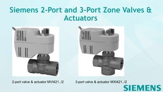
- 1. Siemens 2-Port and 3-Port Zone Valves & Actuators 2-port valve & actuator MVI421../2 3-port valve & actuator MXI421../2
- 2. Operating voltage AC 230 V, 2-position control signal Spring return Positioning force 200 N Direct mounting with union nut, no tools required Ergonomically designed manual adjuster Auxiliary switch, type ASC2.1/18 (optional) Hot-pressed brass valve body DN 15, DN 20 and DN 25 kvs 2…5 m3/h Internally threaded connections Rp.. to ISO 7-1
- 3. Use In ventilation and air conditioning systems for water-side terminal unit control in closed circuits, e.g. induction units, fan coil units, small re-heaters and small re- coolers, for use in In closed-circuit zone heating systems, e.g. 2-pipe systems with 1 heat exchanger for heating and cooling 4-pipe systems with 2 separate heat exchangers for heating and cooling - Separate floors in a building - Apartments - Individual rooms - Floor heating
- 4. Type Type Stock number DN Connections PN class kvs A®AB [m3/h] MVI421.1 5/2 S55310- M100 15 Rp ½“ 16 2.15 MVI421.2 0/2 S55310- M101 20 Rp ¾“ 3.5 MVI421.2 5/2 S55310- M102 25 Rp 1“ 5.0 Type Stock number DN Connections PN class kvs ABàA [m3/h ] kvs ABàB [m3/h ] MXI421.1 5/2 S55310- M103 15 Rp ½“ 16 2.15 1.5 MXI421.2 0/2 S55310- M104 20 Rp ¾“ 3.5 2.5 MXI421.2 5/2 S55310- M105 25 Rp 1“ 5.0 3.5 Valves Actuator 2-port 3-port Dps [kPa ] Dpmax [kPa] Positioning force Contro l signal MVI421. 15/2 MXI421. 15/2 300 300 1) 200 N 2- positio n MVI421. 20/2 MXI421. 20/2 300 300 1) MVI421. 25/2 MXI421 .25/2 250 250 1)
- 5. Technical and Mechanical design The zone valves are closed when de-energised. An on/off controller (thermostat) is required to drive the motorised valve actuators. If the temperature of the medium deviates from the set point, the controller delivers a control signal that drives the actuators, causing the valve to open. When the temperature of the medium reaches the set point the control signal is cut off and the valve closes. The valve is opened electrically by the actuator and closed by spring force. The actuator incorporates a synchronous motor, a gear mechanism and a return spring. The electric motor is overload-resistant and anti-locking, so that continuous operation is possible. The maximum stroke is limited mechanically. The closing motion, by contrast, includes an overrun for the gear mechanism. This protects the gear mechanism from mechanical shock and increases service life.
- 6. Engineering notes Electrical installation The admissible temperatures (see «Technical data») must be observed. The actuator may be operated only with alternating current AC 230 V. For safety and protection reasons connect the actuator with a suitable cable conduit, e.g. Phase cut and pulse-duration-modulated signals are not suitable. Recommended number of opening/closing operations: approx. 50 per day, with 200 heating or cooling days The valves should preferably be installed in the return, where the seals are exposed to lower temperatures. It is not allowed to put a shut off at the bypass port B.
- 7. Mounting notes Mounting instructions A6V11250782 are enclosed with the packaging Orientation The direction of flow as described under «Engineering notes» must be observed. Assembly is made with the coupling nut; no adjustments are required. Mounting The actuator must be fitted in position 1 (also refer to «Manual operation»): Position the actuator and tighten the coupling nut manually Do not use any tools such as wrenches The actuator must not be lagged Commissioning notes The valve may be commissioned only with the manual wheel pre-set or with a correctly mounted actuator. Check the wiring. Check the functioning of the actuator and of the auxiliary switch, if fitted.
- 8. Mounting notes Open valve manually 4867Z08 a 4867Z09 b The lever is locked into position at a valve opening of approx. 90 % Release lever manually4867Z10 Rotate lever as far as the mechanical stop and release. Manual adjustment The valve can be opened manually by use of a lever on the actuator. When the valve is approximately 90% open the lever locks into position. When electrical operation is resumed, the locking mechanism is released automatically. The valves will be opened by their own spring (normally open).
- 9. Technical data Valves Operating data PN class Permissible operating pressure Valve characteristic Leakage 2-port valve: Path A ® AB 3-port valve: Path AB ® A Bypass AB ® B • PN 16 to EN 12266-1 • 1600 kPa (16 bar) • The valves are designed for ON/OFF control only. • According to DIN EN 1349 • 0…0.05 % of kvs • 0…0.05 % of kvs • Max. 2…5 % of kvs • Permissible media • Temperature of medium • Nominal stroke Chilled water, low-temperature hot water and water with antifreeze. Recommendation: water should be treated as specified in VDI 2035. 1...110 °C 2.5 mm Materials • Valve body • Stem • Plug, seat, gland • Sealing glands • Hot-pressed brass • Stainless steel • Brass • EPDM O-rings
- 10. Technical data Actuators Power supply • Operating voltage • Voltage tolerance • Frequency • Power consumption • Primary fuse • AC 230 V • -15/+10 % • 50/60 Hz • 12 VA • External (max 3 A) Control • Positioning signal • Parallel operation of several actuators • Opening / closing operations Position with de-energized actuator • 2-port valve (MVI421../2) • 3-port valve (MXI421../2) • 2-position 1) • Permitted 2) • Recommended number: approx. 10‘000 / year (equivalent to approx. 50 per day) • A ® AB closed • AB A closed Operating data • Positioning time (open / close) • Nominal stroke • Positioning force • Manual adjustment • 50 Hz: 10 s if 60 Hz: 8 s • 2.5 mm • 200 N • 0…90 %
- 11. Technical data Actuators Weight without auxiliary switch with auxiliary switch • 0.585 kg • 0.692 kg Materials • Base-plate • Housing • Union nut • die-cast aluminum • PBT • Brass, nickel plated mat Housing colors • Base and cover • Lever • Light gray, RAL7035 • Pigeon blue, RAL5014 General ambient conditions Operation EN 60721-3-3 Transport EN 60721-3-2 Storage EN 60721-3-2 Environmental Conditions Class 3K3 Class 2K3 Class 2K3 Temperature 1...50 °C -25...70 °C -5...50 °C Humidity 5...85 % r. h. < 95 % r. h. 5...95 % r. h.
- 12. Connecting cable and terminals Actuator N brown blue yellow/green L Q14 Q12 Q11 System neutral System potential AC 230 V Earth Connection diagram N Controller (thermostat) Y Actuator with zone valve L System potential AC 230 V N System neutral Y1 Control signal OPEN Q1 Controller contact Q14 Q12 Q11 black / pink black / blue black / red 0...50 %: Q11 → Q12 50 %...1: Q11 → Q14
- 13. Dimensions L2 L1 58 280 2-port valves MXI421../2 Type DN Rp [inches] L1 [mm] L2 [mm] kg MVI421.15/2 15 Rp½ 60 30 0.796 MVI421.20/2 20 Rp¾ 65 32.5 0.837 MVI421.25/2 25 Rp1 84 45 1.077
- 14. Dimensions 58 Rp 3-port valves MXI421../2 280 280 Type DN Rp [inches] L1 [mm] L2 [mm] L3 [mm] kg MVI421.1 5/2 15 Rp½ 60 30 30 0.844 MVI421.2 0/2 20 Rp¾ 65 32.5 32.5 0.892 MVI421.2 5/2 25 Rp1 84 40 40 1.168