Download to read offline

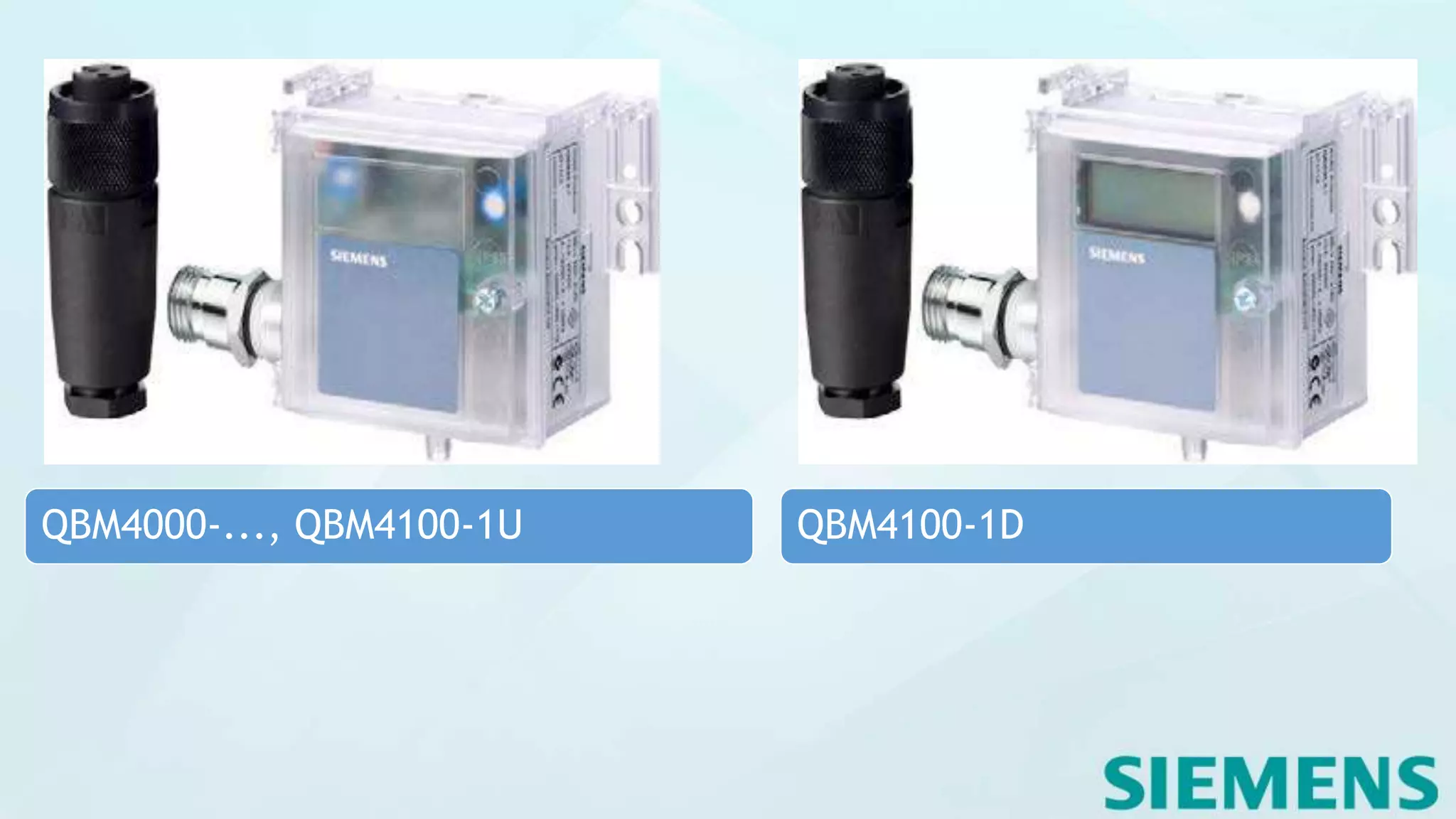
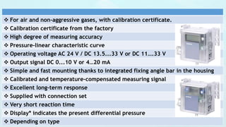
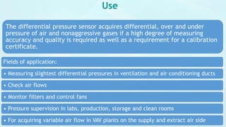
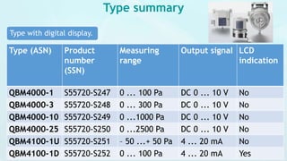
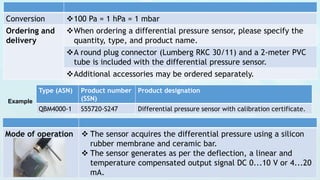
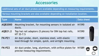
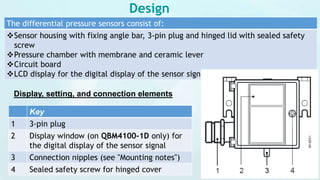
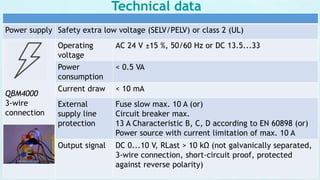
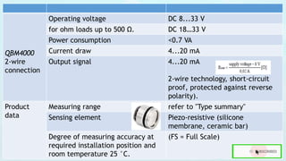
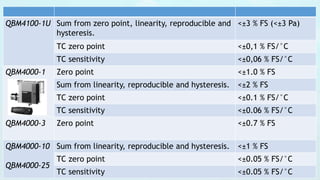
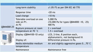
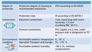

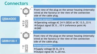
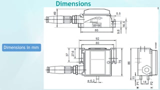

The document provides detailed specifications for differential pressure sensors (QBM4000 and QBM4100 models) designed for measuring air and non-aggressive gases, highlighting their accuracy, calibration certifications, and operational features such as output signals and response times. It includes information about installation requirements, accessories, and maintenance while emphasizing safety precautions and compliance with electrical standards. The document also outlines environmental conditions, technical data, and disposal guidelines for these sensors.