Downloaded 210 times


![Microwave Engineering
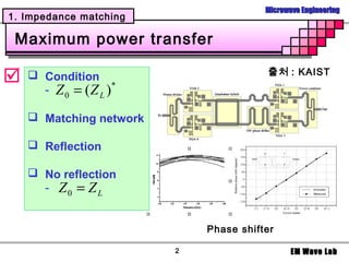
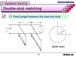
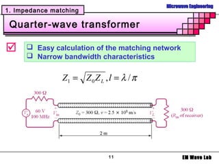
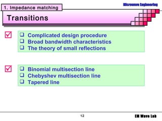
1. Impedance matching
Example
Design the L section matching network to
match the transmission line,
where
Z L = 200 − j100[ Ω], Z 0 = 100[ Ω], f = 500 MHz
Smith chart
5 EM Wave Lab](https://image.slidesharecdn.com/7-impedancematching-120810003454-phpapp01/85/Impedance-Matching-5-320.jpg)


![Microwave Engineering
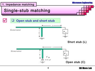
1. Impedance matching
Example
Design the single-stub shunt tuning network to
match the transmission line,
where
Z L = 15 + j10[ Ω], Z 0 = 50[ Ω], f = 2GHz
Smith chart
9 EM Wave Lab](https://image.slidesharecdn.com/7-impedancematching-120810003454-phpapp01/85/Impedance-Matching-9-320.jpg)

The document discusses impedance matching in microwave engineering. It covers: 1. The conditions required for maximum power transfer between a transmission line and load, which is when their impedances are equal. 2. Various matching network topologies that can be used including L-networks, T-networks, and pi-networks using lumped elements, as well as single-stub, double-stub, and quarter-wave transformer matching networks. 3. Design procedures and examples for L-network, single-stub shunt tuning, and double-stub matching networks using the Smith Chart. Transitions with broader bandwidth than quarter-wave transformers like binomial and Chebyshev multisection lines are also covered.