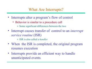
Interrupts
What Are Interrupts?
• Interrupts alter a program’s flow of control
   ∗ Behavior is similar to a procedure call
      » Some significant differences between the two
• Interrupt causes transfer of control to an interrupt
  service routine (ISR)
      » ISR is also called a handler
• When the ISR is completed, the original program
  resumes execution
• Interrupts provide an efficient way to handle
  unanticipated events
Interrupts versus Procedures
           Interrupts                      Procedures
•   Initiated by both software   •   Can only be initiated by
    and hardware                     software
•   Can handle anticipated       •   Can handle anticipated
    and unanticipated internal       events that are coded into
    as well as external events       the program
•   ISRs or interrupt handlers   •   Typically loaded along
    are memory resident              with the program
•   Use numbers to identify      •   Use meaningful names to
    an interrupt service             indicate their function
•   (E)FLAGS register is         •   Do not save the
    saved automatically
                                     (E)FLAGS register
A Taxonomy of Pentium Interrupts
Various Ways of Interacting with I/O Devices
Interrupt Processing in Real Mode
• Uses an interrupt vector table that stores pointers
  to the associated interrupt handlers.
   ∗ This table is located at base address zero.
• Each entry in this table consists of a CS:IP pointer
  to the associated ISRs
   ∗ Each entry or vector requires four bytes:
      » Two bytes for specifying CS
      » Two bytes for the offset
• Up to 256 interrupts are supported (0 to 255).
Interrupt Vector Table
Interrupt Number to Vector Translation
• Interrupt numbers range       Example
  from 0 to 255                 • For interrupt 2, the
                                  memory address is
• Interrupt number acts as               2 ∗ 4 = 8H
  an index into the interrupt   • The first two bytes at 8H
  vector table                    are taken as the offset
                                  value
• Since each vector takes 4     • The next two bytes (i.e., at
  bytes, interrupt number is      address AH) are used as
  multiplied by 4 to get the      the CS value
  corresponding ISR pointer
A Typical ISR Structure
• Just like procedures, ISRs should end with a return
  statement to return control back
• The interrupt return (iret) is used of this purpose
   ;save the registers used in the ISR
   sti      ;enable further interrupts
   . . .
   ISR body
   . . .
   ;restore the saved registers
   iret     ;return to interrupted program
What Happens When An Interrupt Occurs?
• Push flags register onto the stack
• Clear interrupt enable and trap flags
   ∗ This disables further interrupts
   ∗ Use sti to enable interrupts
• Push CS and IP registers onto the stack
• Load CS with the 16-bit data at memory address
      interrupt-type ∗ 4 + 2
• Load IP with the 16-bit data at memory address
      interrupt-type ∗ 4
Interrupt Enable Flag Instructions
• Interrupt enable flag controls whether the
  processor should be interrupted or not
• Clearing this flag disables all further interrupts
  until it is set
   ∗ Use cli (clear interrupt) instruction for this purpose
   ∗ It is cleared as part interrupt processing
• Unless there is special reason to block further
  interrupts, enable interrupts in your ISR
   ∗ Use sti (set interrupt) instruction for this purpose
Returning From An ISR
• As in procedures, the last instruction in an ISR
  should be iret
• The actions taken on iret are:
   ∗ pop the 16-bit value on top of the stack into IP register
   ∗ pop the 16-bit value on top of the stack into CS register
   ∗ pop the 16-bit value on top of the stack into the flags
     register
• As in procedures, make sure that your ISR does
  not leave any data on the stack
   ∗ Match your push and pop operations within the ISR
Dedicated Interrupts
• Several Pentium predefined interrupts --- called
  dedicated interrupts
• These include the first five interrupts:
   interrupt type   Purpose
       0            Divide error
       1            Single-step
       2            Nonmaskable interrupt (MNI)
       3            Breakpoint
       4            Overflow
Dedicated Interrupts (cont’d)
• Divide Error Interrupt
   ∗ CPU generates a type 0 interrupt whenever the div/idiv
     instructions result in a quotient that is larger than the
     destination specified
• Single-Step Interrupt
   ∗ Useful in debugging
   ∗ To single step, Trap Flag (TF) should be set
   ∗ CPU automatically generates a type 1 interrupt after
     executing each instruction if TF is set
   ∗ Type 1 ISR can be used to present the system state to
     the user
Dedicated Interrupts (cont’d)
• Breakpoint Interrupt
   ∗ Useful in debugging
   ∗ CPU generates a type 3 interrupt
   ∗ Generated by executing a special single-byte version of
     int 3 instruction (opcode CCH)
• Overflow Interrupt
   ∗ Two ways of generating this type 4 interrupt
      » int 4 (unconditionally generates a type 4 interrupt)
      » into (interrupt is generated only if the overflow flag is set)
   ∗ We do not normally use into as we can use jo/jno
     conditional jumps to take care of overflow
A Single-Step Interrupt Example
• Objectives:
   ∗ To demonstrate how ISRs can be defined and installed
     (i.e., user defined ISRs)
   ∗ How trap flag can be manipulated
      » There are no instruction to set/clear the trap flag unlike the
        interrupt enable flag sti/cli
• We write our own type 1 ISR that displays the
  contents of AX and BX registers after each
  instruction has been executed
Hardware Interrupts
• Software interrupts are synchronous events
   ∗ Caused by executing the int instruction
• Hardware interrupts are of hardware origin and
  asynchronous in nature
   ∗ Typically caused by applying an electrical signal to the
     processor chip
• Hardware interrupts can be
   ∗ Maskable
   ∗ Non-maskable
      » Causes a type 2 interrupt
How Are Hardware Interrupts Triggered?
• Non-maskable interrupt is triggered by applying
  an electrical signal to the MNI pin of Pentium
   ∗ Processor always responds to this signal
   ∗ Cannot be disabled under program control
• Maskable interrupt is triggered by applying an
  electrical signal to the INTR (INTerrupt Request)
  pin of Pentium
   ∗ Pentium recognizes this interrupt only if IF (interrupt
     enable flag) is set
   ∗ Interrupts can be masked or disabled by clearing IF
How Does the CPU Know the Interrupt Type?
• Interrupt invocation process is common to all
  interrupts
   ∗ Whether originated in software or hardware
• For hardware interrupts, CPU initiates an interrupt
  acknowledge sequence
   ∗ CPU sends out interrupt acknowledge (INTA) signal
   ∗ In response, interrupting device places interrupt type
     number on the data bus
   ∗ CPU uses this number to invoke the ISR that should
     service the device (as in software interrupts)
How can More Than One Device Interrupt?
• Processor has only one INTR pin to receive
  interrupt signal
• Typical system has more than one device that can
  interrupt --- keyboard, hard disk, floppy, etc.
• Use a special chip to prioritize the interrupts and
  forward only one interrupt to the CPU
• 8259 Programmable Interrupt Controller chip
  performs this function (more details later)
8259 Programmable Interrupt Controller
• 8259 can service up to eight hardware devices
   ∗ Interrupts are received on IRQ0 through IRQ7
• 8259 can be programmed to assign priorities in
  several ways
   ∗ Fixed priority scheme is used in the PC
      » IRQ0 has the highest priority and IRQ7 lowest
• 8259 has two registers
   ∗ Interrupt Command Register (ICR)
      » Used to program 8259
   ∗ Interrupt Mask Register (IMR)
8259 PIC (cont’d)
8259 Programmable Interrupt Controller
8259 Programmable Interrupt Controller Block Diagram

63071507 interrupts-up

  • 1.
  • 2.
    What Are Interrupts? •Interrupts alter a program’s flow of control ∗ Behavior is similar to a procedure call » Some significant differences between the two • Interrupt causes transfer of control to an interrupt service routine (ISR) » ISR is also called a handler • When the ISR is completed, the original program resumes execution • Interrupts provide an efficient way to handle unanticipated events
  • 3.
    Interrupts versus Procedures Interrupts Procedures • Initiated by both software • Can only be initiated by and hardware software • Can handle anticipated • Can handle anticipated and unanticipated internal events that are coded into as well as external events the program • ISRs or interrupt handlers • Typically loaded along are memory resident with the program • Use numbers to identify • Use meaningful names to an interrupt service indicate their function • (E)FLAGS register is • Do not save the saved automatically (E)FLAGS register
  • 4.
    A Taxonomy ofPentium Interrupts
  • 5.
    Various Ways ofInteracting with I/O Devices
  • 6.
    Interrupt Processing inReal Mode • Uses an interrupt vector table that stores pointers to the associated interrupt handlers. ∗ This table is located at base address zero. • Each entry in this table consists of a CS:IP pointer to the associated ISRs ∗ Each entry or vector requires four bytes: » Two bytes for specifying CS » Two bytes for the offset • Up to 256 interrupts are supported (0 to 255).
  • 7.
  • 8.
    Interrupt Number toVector Translation • Interrupt numbers range Example from 0 to 255 • For interrupt 2, the memory address is • Interrupt number acts as 2 ∗ 4 = 8H an index into the interrupt • The first two bytes at 8H vector table are taken as the offset value • Since each vector takes 4 • The next two bytes (i.e., at bytes, interrupt number is address AH) are used as multiplied by 4 to get the the CS value corresponding ISR pointer
  • 9.
    A Typical ISRStructure • Just like procedures, ISRs should end with a return statement to return control back • The interrupt return (iret) is used of this purpose ;save the registers used in the ISR sti ;enable further interrupts . . . ISR body . . . ;restore the saved registers iret ;return to interrupted program
  • 10.
    What Happens WhenAn Interrupt Occurs? • Push flags register onto the stack • Clear interrupt enable and trap flags ∗ This disables further interrupts ∗ Use sti to enable interrupts • Push CS and IP registers onto the stack • Load CS with the 16-bit data at memory address interrupt-type ∗ 4 + 2 • Load IP with the 16-bit data at memory address interrupt-type ∗ 4
  • 11.
    Interrupt Enable FlagInstructions • Interrupt enable flag controls whether the processor should be interrupted or not • Clearing this flag disables all further interrupts until it is set ∗ Use cli (clear interrupt) instruction for this purpose ∗ It is cleared as part interrupt processing • Unless there is special reason to block further interrupts, enable interrupts in your ISR ∗ Use sti (set interrupt) instruction for this purpose
  • 12.
    Returning From AnISR • As in procedures, the last instruction in an ISR should be iret • The actions taken on iret are: ∗ pop the 16-bit value on top of the stack into IP register ∗ pop the 16-bit value on top of the stack into CS register ∗ pop the 16-bit value on top of the stack into the flags register • As in procedures, make sure that your ISR does not leave any data on the stack ∗ Match your push and pop operations within the ISR
  • 13.
    Dedicated Interrupts • SeveralPentium predefined interrupts --- called dedicated interrupts • These include the first five interrupts: interrupt type Purpose 0 Divide error 1 Single-step 2 Nonmaskable interrupt (MNI) 3 Breakpoint 4 Overflow
  • 14.
    Dedicated Interrupts (cont’d) •Divide Error Interrupt ∗ CPU generates a type 0 interrupt whenever the div/idiv instructions result in a quotient that is larger than the destination specified • Single-Step Interrupt ∗ Useful in debugging ∗ To single step, Trap Flag (TF) should be set ∗ CPU automatically generates a type 1 interrupt after executing each instruction if TF is set ∗ Type 1 ISR can be used to present the system state to the user
  • 15.
    Dedicated Interrupts (cont’d) •Breakpoint Interrupt ∗ Useful in debugging ∗ CPU generates a type 3 interrupt ∗ Generated by executing a special single-byte version of int 3 instruction (opcode CCH) • Overflow Interrupt ∗ Two ways of generating this type 4 interrupt » int 4 (unconditionally generates a type 4 interrupt) » into (interrupt is generated only if the overflow flag is set) ∗ We do not normally use into as we can use jo/jno conditional jumps to take care of overflow
  • 16.
    A Single-Step InterruptExample • Objectives: ∗ To demonstrate how ISRs can be defined and installed (i.e., user defined ISRs) ∗ How trap flag can be manipulated » There are no instruction to set/clear the trap flag unlike the interrupt enable flag sti/cli • We write our own type 1 ISR that displays the contents of AX and BX registers after each instruction has been executed
  • 17.
    Hardware Interrupts • Softwareinterrupts are synchronous events ∗ Caused by executing the int instruction • Hardware interrupts are of hardware origin and asynchronous in nature ∗ Typically caused by applying an electrical signal to the processor chip • Hardware interrupts can be ∗ Maskable ∗ Non-maskable » Causes a type 2 interrupt
  • 18.
    How Are HardwareInterrupts Triggered? • Non-maskable interrupt is triggered by applying an electrical signal to the MNI pin of Pentium ∗ Processor always responds to this signal ∗ Cannot be disabled under program control • Maskable interrupt is triggered by applying an electrical signal to the INTR (INTerrupt Request) pin of Pentium ∗ Pentium recognizes this interrupt only if IF (interrupt enable flag) is set ∗ Interrupts can be masked or disabled by clearing IF
  • 19.
    How Does theCPU Know the Interrupt Type? • Interrupt invocation process is common to all interrupts ∗ Whether originated in software or hardware • For hardware interrupts, CPU initiates an interrupt acknowledge sequence ∗ CPU sends out interrupt acknowledge (INTA) signal ∗ In response, interrupting device places interrupt type number on the data bus ∗ CPU uses this number to invoke the ISR that should service the device (as in software interrupts)
  • 22.
    How can MoreThan One Device Interrupt? • Processor has only one INTR pin to receive interrupt signal • Typical system has more than one device that can interrupt --- keyboard, hard disk, floppy, etc. • Use a special chip to prioritize the interrupts and forward only one interrupt to the CPU • 8259 Programmable Interrupt Controller chip performs this function (more details later)
  • 24.
    8259 Programmable InterruptController • 8259 can service up to eight hardware devices ∗ Interrupts are received on IRQ0 through IRQ7 • 8259 can be programmed to assign priorities in several ways ∗ Fixed priority scheme is used in the PC » IRQ0 has the highest priority and IRQ7 lowest • 8259 has two registers ∗ Interrupt Command Register (ICR) » Used to program 8259 ∗ Interrupt Mask Register (IMR)
  • 25.
  • 26.
  • 27.
    8259 Programmable InterruptController Block Diagram