Microprocessor - 8086Interrupts
Interrupt is the method of creating a temporary
halt during program execution and allows
peripheral devices to access the microprocessor.
The microprocessor responds to that interrupt
with an ISR (Interrupt Service Routine), which is
a short program to instruct the microprocessor
on how to handle the interrupt.
2.
The following imageshows the types of interrupts we
have in a 8086 microprocessor
3.
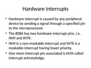
Hardware Interrupts
• Hardwareinterrupt is caused by any peripheral
device by sending a signal through a specified pin
to the microprocessor.
• The 8086 has two hardware interrupt pins, i.e.
NMI and INTR.
• NMI is a non-maskable interrupt and INTR is a
maskable interrupt having lower priority.
• One more interrupt pin associated is INTA called
interrupt acknowledge.
4.
NMI
• It isa single non-maskable interrupt pin (NMI) having higher
priority than the maskable interrupt request pin (INTR)and
it is of type 2 interrupt.
• When this interrupt is activated, these actions take place −
Completes the current instruction that is in progress.
Pushes the Flag register values on to the stack.
Pushes the CS (code segment) value and IP (instruction
pointer) value of the return address on to the stack.
IP is loaded from the contents of the word location 00008H.
CS is loaded from the contents of the next word location
0000AH.
Interrupt flag and trap flag are reset to 0.
5.
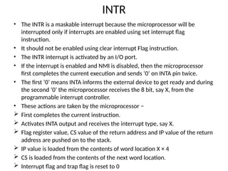
INTR
• The INTRis a maskable interrupt because the microprocessor will be
interrupted only if interrupts are enabled using set interrupt flag
instruction.
• It should not be enabled using clear interrupt Flag instruction.
• The INTR interrupt is activated by an I/O port.
• If the interrupt is enabled and NMI is disabled, then the microprocessor
first completes the current execution and sends ‘0’ on INTA pin twice.
• The first ‘0’ means INTA informs the external device to get ready and during
the second ‘0’ the microprocessor receives the 8 bit, say X, from the
programmable interrupt controller.
• These actions are taken by the microprocessor −
First completes the current instruction.
Activates INTA output and receives the interrupt type, say X.
Flag register value, CS value of the return address and IP value of the return
address are pushed on to the stack.
IP value is loaded from the contents of word location X × 4
CS is loaded from the contents of the next word location.
Interrupt flag and trap flag is reset to 0
6.
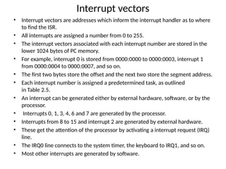
Interrupt vectors
• Interruptvectors are addresses which inform the interrupt handler as to where
to find the ISR.
• All interrupts are assigned a number from 0 to 255.
• The interrupt vectors associated with each interrupt number are stored in the
lower 1024 bytes of PC memory.
• For example, interrupt 0 is stored from 0000:0000 to 0000:0003, interrupt 1
from 0000:0004 to 0000:0007, and so on.
• The first two bytes store the offset and the next two store the segment address.
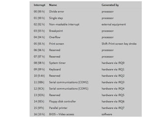
• Each interrupt number is assigned a predetermined task, as outlined
in Table 2.5.
• An interrupt can be generated either by external hardware, software, or by the
processor.
• Interrupts 0, 1, 3, 4, 6 and 7 are generated by the processor.
• Interrupts from 8 to 15 and interrupt 2 are generated by external hardware.
• These get the attention of the processor by activating a interrupt request (IRQ)
line.
• The IRQ0 line connects to the system timer, the keyboard to IRQ1, and so on.
• Most other interrupts are generated by software.
11.
• In aninterrupt vector table, the first five
interrupt vectors are identical in all
Intel microprocessor family members, from the
8086 to the Pentium.
• Other interrupt vectors exist for the 80286 that
are upward-compatible to 80386, 80486, and
Pentium to Pentium 4, but not downward-
compatible to the 8086 or 8088.
• Intel reserves the first 32 interrupt vectors for its
use in various microprocessor family members.
• The last 224 vectors are available as user
interrupt vectors.
12.
Software Interrupts
• Someinstructions are inserted at the desired
position into the program to create interrupts.
• These interrupt instructions can be used to
test the working of various interrupt handlers.
13.
INT- Interrupt instructionwith type number
• It is 2-byte instruction.
• First byte provides the op-code and the second byte provides
the interrupt type number.
• There are 256 interrupt types under this group.
• Its execution includes the following steps −
Flag register value is pushed on to the stack.
CS value of the return address and IP value of the return
address are pushed on to the stack.
IP is loaded from the contents of the word location ‘type
number’ × 4
CS is loaded from the contents of the next word location.
Interrupt Flag and Trap Flag are reset to 0
The starting address for type0 interrupt is 000000H, for type1
interrupt is 00004H similarly for type2 is 00008H and ……so on.
14.
First Five Pointers
•The first five pointers are dedicated interrupt pointers.
i.e. −
TYPE 0 interrupt represents division by zero situation.
TYPE 1 interrupt represents single-step execution
during the debugging of a program.
TYPE 2 interrupt represents non-maskable NMI
interrupt.
TYPE 3 interrupt represents break-point interrupt.
TYPE 4 interrupt represents overflow interrupt.
• The interrupts from Type 5 to Type 31 are reserved for
other advanced microprocessors, and
• interrupts from 32 to Type 255 are available for
hardware and software interrupts.
15.
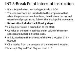
INT 3-Break PointInterrupt Instruction
• It is a 1-byte instruction having op-code is CCH.
• These instructions are inserted into the program so that
when the processor reaches there, then it stops the normal
execution of program and follows the break-point procedure.
• Its execution includes the following steps −
Flag register value is pushed on to the stack.
CS value of the return address and IP value of the return
address are pushed on to the stack.
IP is loaded from the contents of the word location 3×4 =
0000CH
CS is loaded from the contents of the next word location.
Interrupt Flag and Trap Flag are reset to 0
16.
INT4 - Interrupton overflow instruction
• It is a 1-byte instruction and their mnemonic INT4.
• The op-code for this instruction is CEH.
• As the name suggests it is a conditional interrupt instruction, i.e.
it is active only when the overflow flag is set to 1 and branches to
the interrupt handler whose interrupt type number is 4.
• If the overflow flag is reset then, the execution continues to the
next instruction.
• Its execution includes the following steps −
Flag register values are pushed on to the stack.
CS value of the return address and IP value of the return address
are pushed on to the stack.
IP is loaded from the contents of word location 4×4 = 00010H
CS is loaded from the contents of the next word location.
Interrupt flag and Trap flag are reset to 0
17.
Interrupt Nesting
• Anotherfeature of this family is that interrupt nesting can be enabled.
With interrupt nesting enabled interrupts can interrupt other interrupts
(but not themselves).
• Yet another feature in this family allows an interrupt level (0–7) to be
assigned to each interrupt handler.
• Instead of a hard interrupts-enabled or -disabled (GIE flag) there is
available a service level number (0–7) that indicates which interrupts are
enabled by level number.
• For example, if the service level is set to 3, only levels 3, 4, 5, 6, and 7 are
serviced, the remaining act like the interrupt is disabled.
• This is used for complex programs where, depending on the current mode
of the program, only certain groups of interrupts are enabled.
• The level also determines which interrupt is invoked first if two interrupts
happen at the same time.
• To set the level for an ISR, use: # int_ext level=3
• Finally there is a group of interrupt sources defined in this family that is
related to program errors. These are called traps but work like interrupts.
• For example, one of the traps is a divide by zero