Download as PDF, PPTX

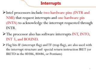
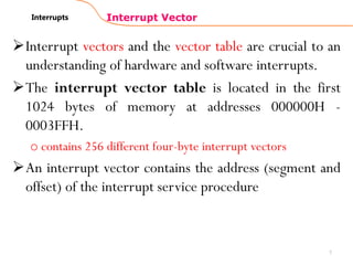

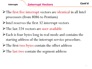
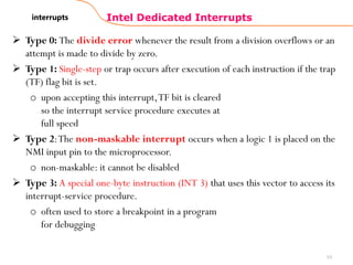

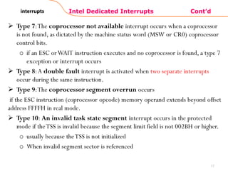
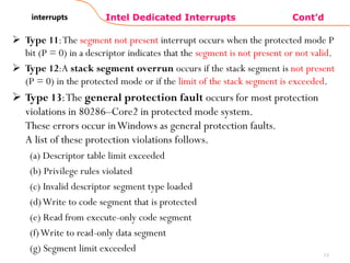

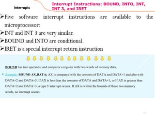


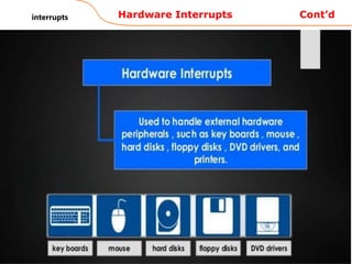


The document explains the interrupt structure of Intel microprocessors, detailing both hardware and software interrupt types and their operations. Key aspects include how interrupts temporarily halt program execution, the significance of flags such as the interrupt enable flag and trap flag, and the function of interrupt vectors and tables. It also discusses various types of interrupts and dedicated interrupt types specific to Intel processors, including error handling and external hardware interactions.