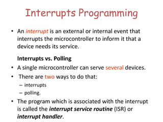
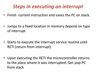
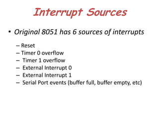
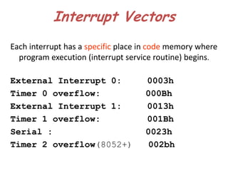
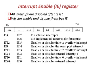
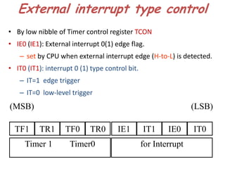
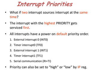
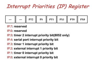
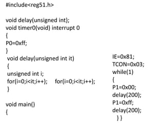
The document discusses interrupts in the 8051 microcontroller. It describes interrupts as events that interrupt normal program flow to service external devices. Interrupts provide faster response than polling. The interrupt service routine starts at a specific memory location. When an interrupt occurs, the program counter is saved and the ISR begins. Upon returning from the ISR, normal code execution resumes. The 8051 has several interrupt sources with different priority levels that determine service order. Interrupt enable bits and edge/level triggering are controlled through registers.
2. Interrupts Programming
• An interrupt is an external or internal event that
interrupts the microcontroller to inform it that a
device needs its service.
Interrupts vs. Polling
• A single microcontroller can serve several devices.
• There are two ways to do that:
– interrupts
– polling.
• The program which is associated with the interrupt
is called the interrupt service routine (ISR) or
interrupt handler.
3. Steps in executing an interrupt
• Finish current instruction and saves the PC on stack.
• Jumps to a fixed location in memory depend on type
of interrupt
• Starts to execute the interrupt service routine until
RETI (return from interrupt)
• Upon executing the RETI the microcontroller returns
to the place where it was interrupted. Get pop PC
from stack
4. Interrupt Sources
• Original 8051 has 6 sources of interrupts
– Reset
– Timer 0 overflow
– Timer 1 overflow
– External Interrupt 0
– External Interrupt 1
– Serial Port events (buffer full, buffer empty, etc)
5. Interrupt Vectors
Each interrupt has a specific place in code memory where
program execution (interrupt service routine) begins.
External Interrupt 0: 0003h
Timer 0 overflow: 000Bh
External Interrupt 1: 0013h
Timer 1 overflow: 001Bh
Serial : 0023h
Timer 2 overflow(8052+) 002bh
6. Interrupt Enable (IE) register
All interrupt are disabled after reset
We can enable and disable them bye IE
7. External interrupt type control
• By low nibble of Timer control register TCON
• IE0 (IE1): External interrupt 0(1) edge flag.
– set by CPU when external interrupt edge (H-to-L) is detected.
• IT0 (IT1): interrupt 0 (1) type control bit.
– IT=1 edge trigger
– IT=0 low-level trigger
(MSB) (LSB)
TF1 TR1 TF0 TR0 IE1 IT1 IE0 IT0
Timer 1 Timer0 for Interrupt
8. Interrupt Priorities
• What if two interrupt sources interrupt at the same
time?
• The interrupt with the highest PRIORITY gets
serviced first.
• All interrupts have a power on default priority order.
1. External interrupt 0 (INT0)
2. Timer interrupt0 (TF0)
3. External interrupt 1 (INT1)
4. Timer interrupt1 (TF1)
5. Serial communication (RI+TI)
• Priority can also be set to “high” or “low” by IP reg.
9. Interrupt Priorities (IP) Register
--- --- PT2 PS PT1 PX1 PT0 PX0
IP.7: reserved
IP.6: reserved
IP.5: timer 2 interrupt priority bit(8052 only)
IP.4: serial port interrupt priority bit
IP.3: timer 1 interrupt priority bit
IP.2: external interrupt 1 priority bit
IP.1: timer 0 interrupt priority bit
IP.0: external interrupt 0 priority bit