Download as PDF, PPTX

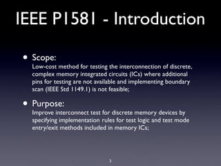
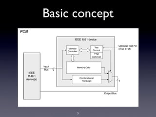
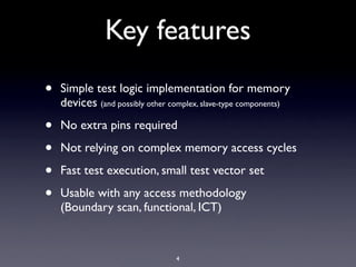
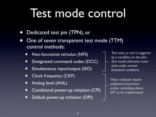

IEEE P1581 provides a standard method for testing interconnects of complex memory ICs without requiring additional test pins. It specifies implementation rules for simple test logic and transparent test mode entry/exit methods. Key features include fast testing with small test vectors without needing complex memory access or additional pins. Test mode is entered via a dedicated test pin, one of seven transparent test mode control methods, or optional test functions. The standard aims to improve testing of memory devices on printed circuit boards.