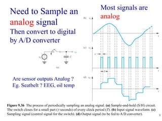
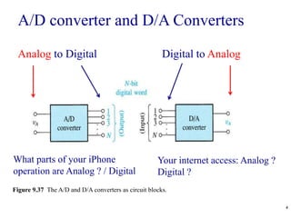
1. Analog to digital converters (ADCs) sample analog signals and convert them into digital words. This allows analog signals from sensors to be processed digitally.
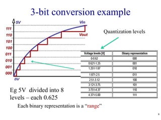
2. The conversion process has two steps - quantization breaks down the analog value into discrete levels, and encoding assigns a digital code to each level. For example, a 3-bit ADC of a 0-10V signal quantizes it into 8 levels separated by 1.25V and encodes each with a 3-bit binary code.
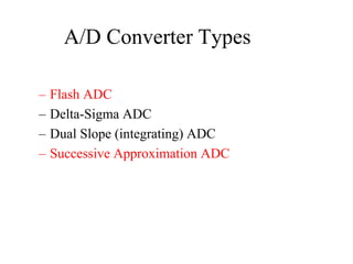
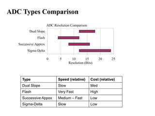
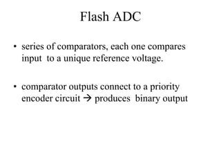
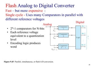
3. There are several types of ADCs including flash, successive approximation, delta-sigma, and dual slope. Flash ADCs are fastest but most expensive, while successive approximation and dual slope ADCs are slower


![9
Figure 2.10 A weighted summer.
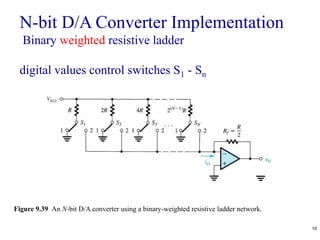
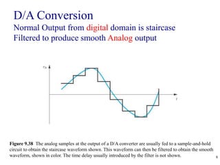
D/A conversion implementation
Weighted Summing Circuit
vo = - [(Rf / R1) * v1 + (Rf / R2) * v2 +….+ (Rf / Rn) * vn]
in = ?
i = ?](https://image.slidesharecdn.com/adcanddac-210909151941/85/Adc-and-dac-9-320.jpg)