chap-3lecture13.pptIEC 61850 Standard For Substation Automation
1.
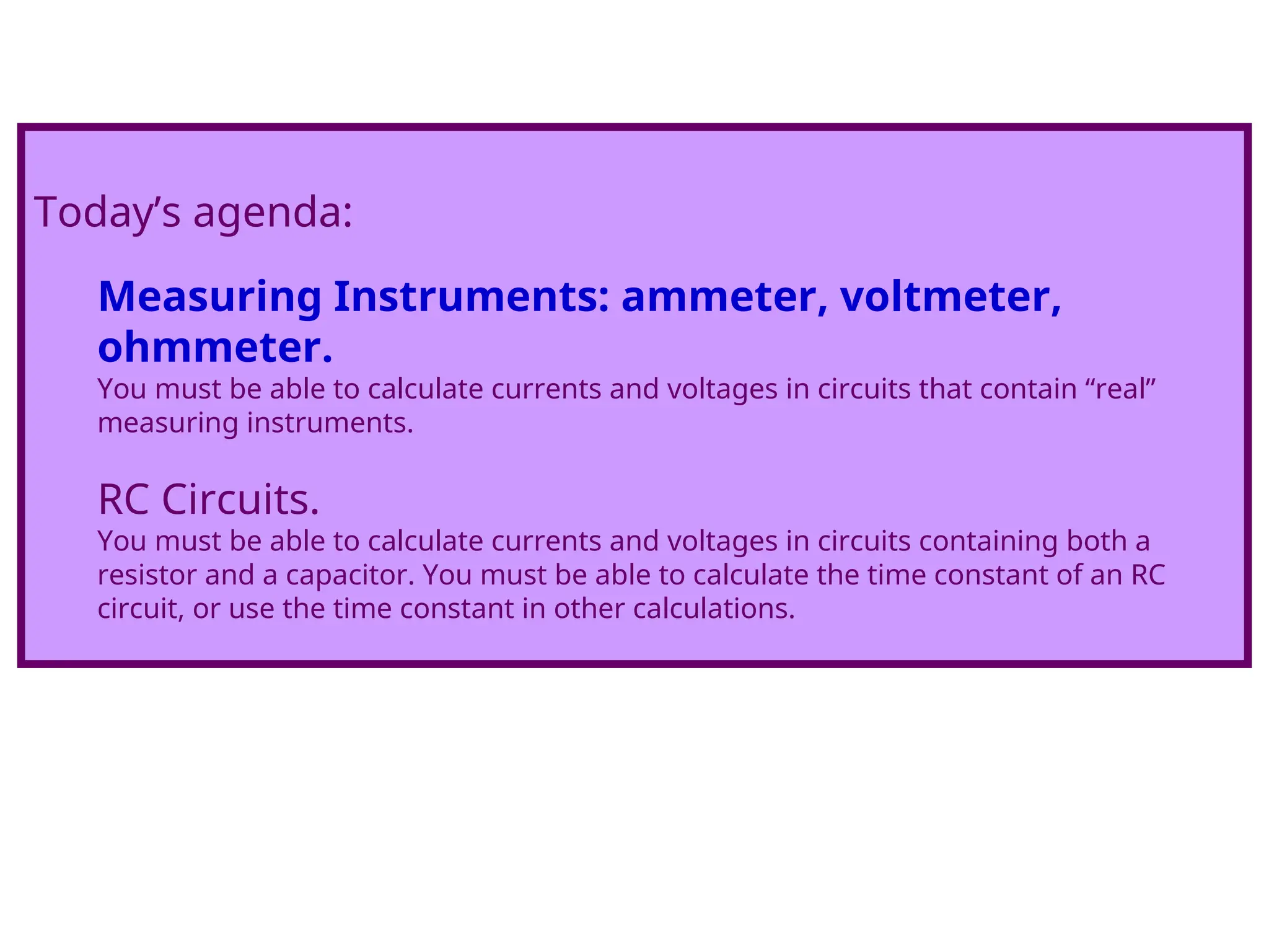
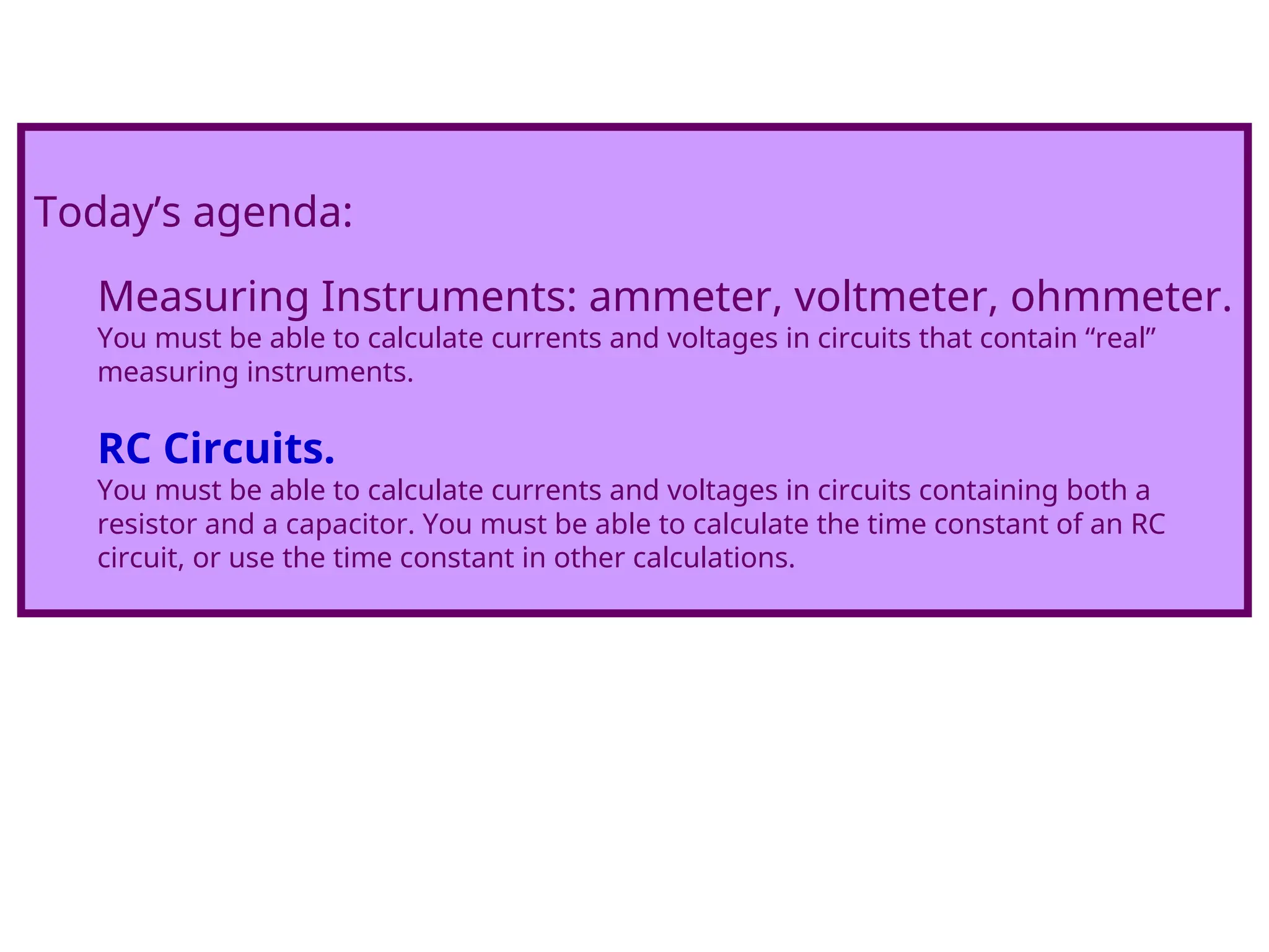
Today’s agenda:
Measuring Instruments:ammeter, voltmeter,
ohmmeter.
You must be able to calculate currents and voltages in circuits that contain “real”
measuring instruments.
RC Circuits.
You must be able to calculate currents and voltages in circuits containing both a
resistor and a capacitor. You must be able to calculate the time constant of an RC
circuit, or use the time constant in other calculations.
2.
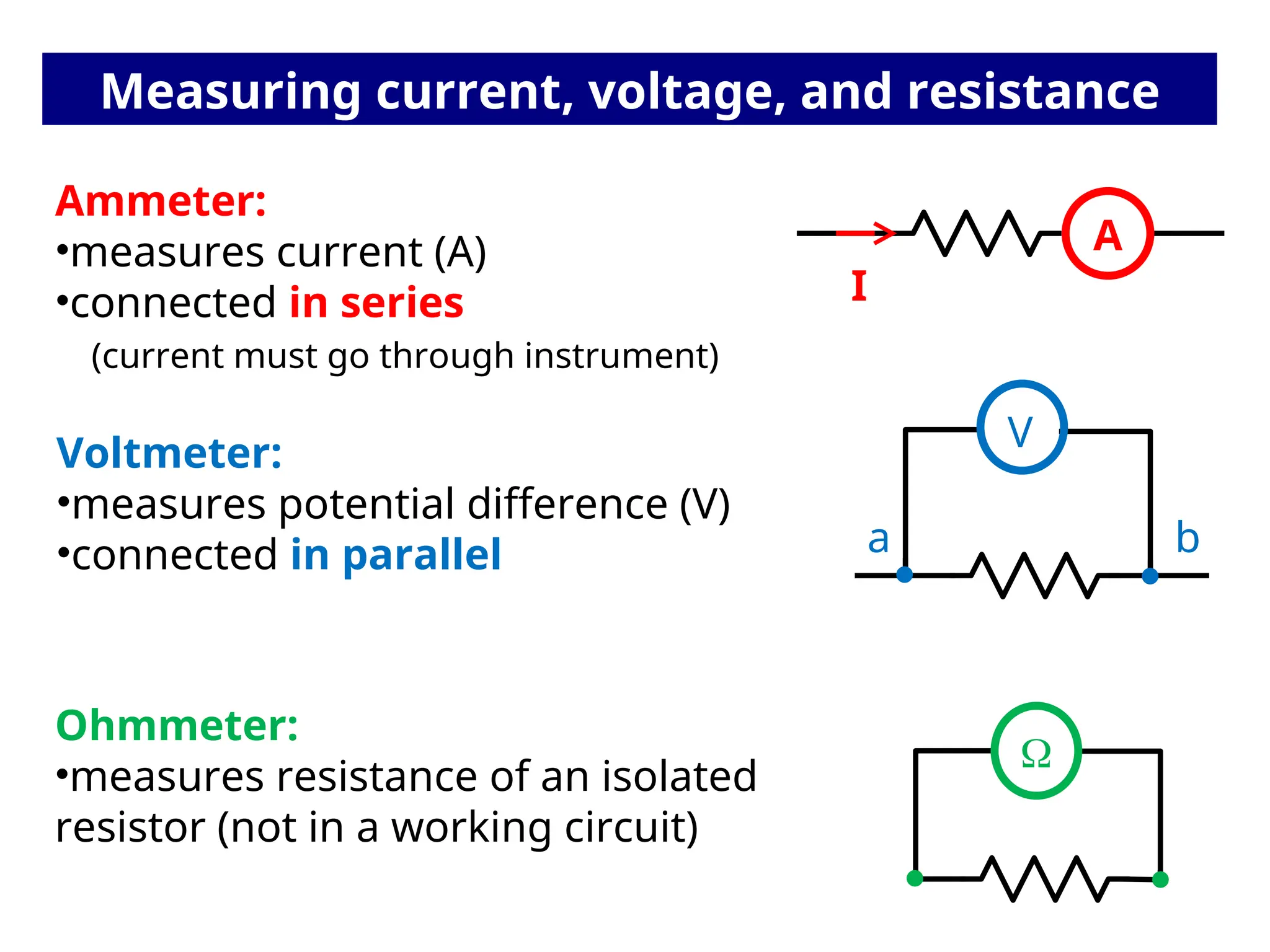
Measuring current, voltage,and resistance
A
Ammeter:
•measures current (A)
•connected in series
(current must go through instrument)
I
V
a b
Voltmeter:
•measures potential difference (V)
•connected in parallel
Ohmmeter:
•measures resistance of an isolated
resistor (not in a working circuit)
3.
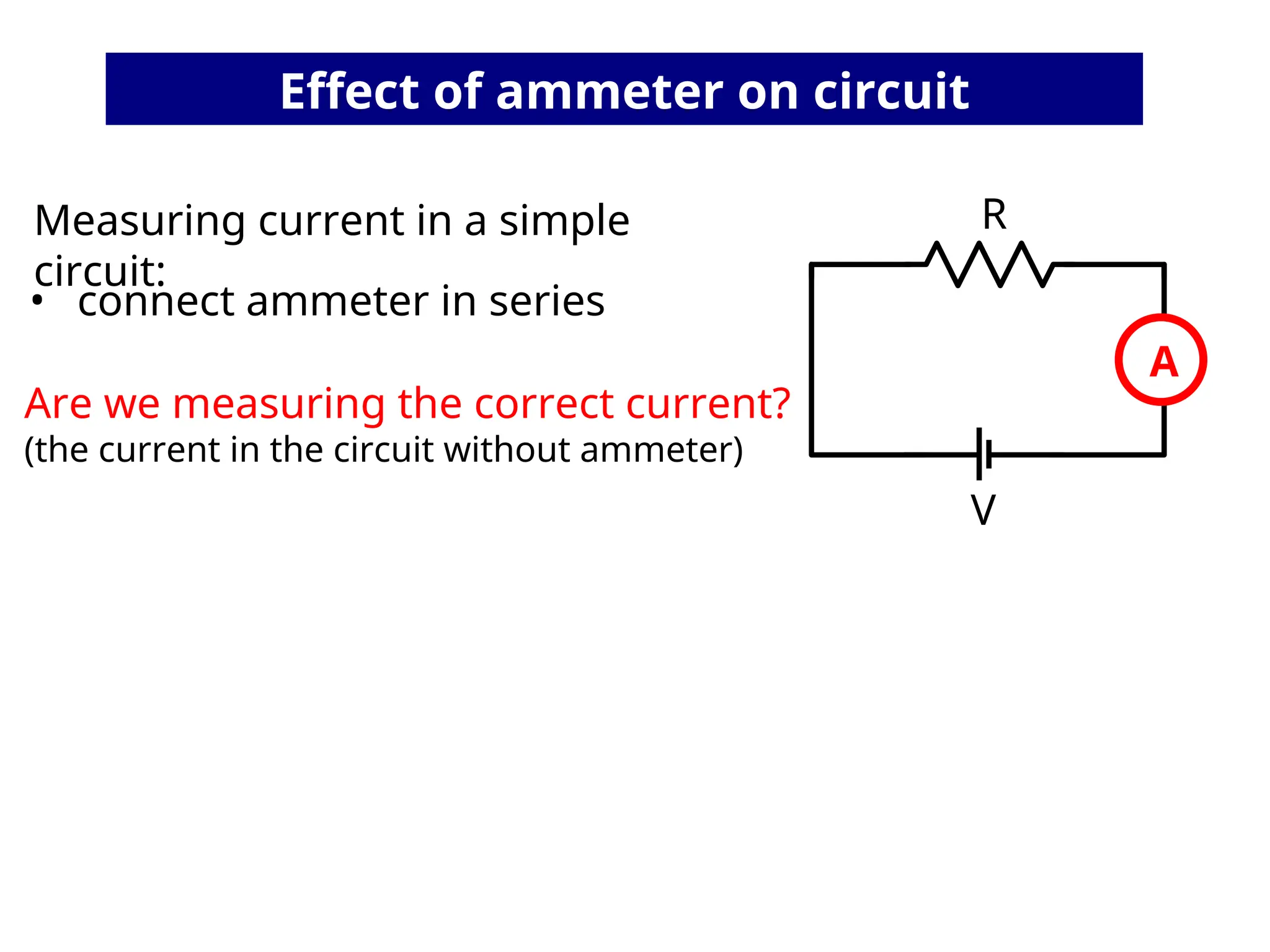
Effect of ammeteron circuit
V
R
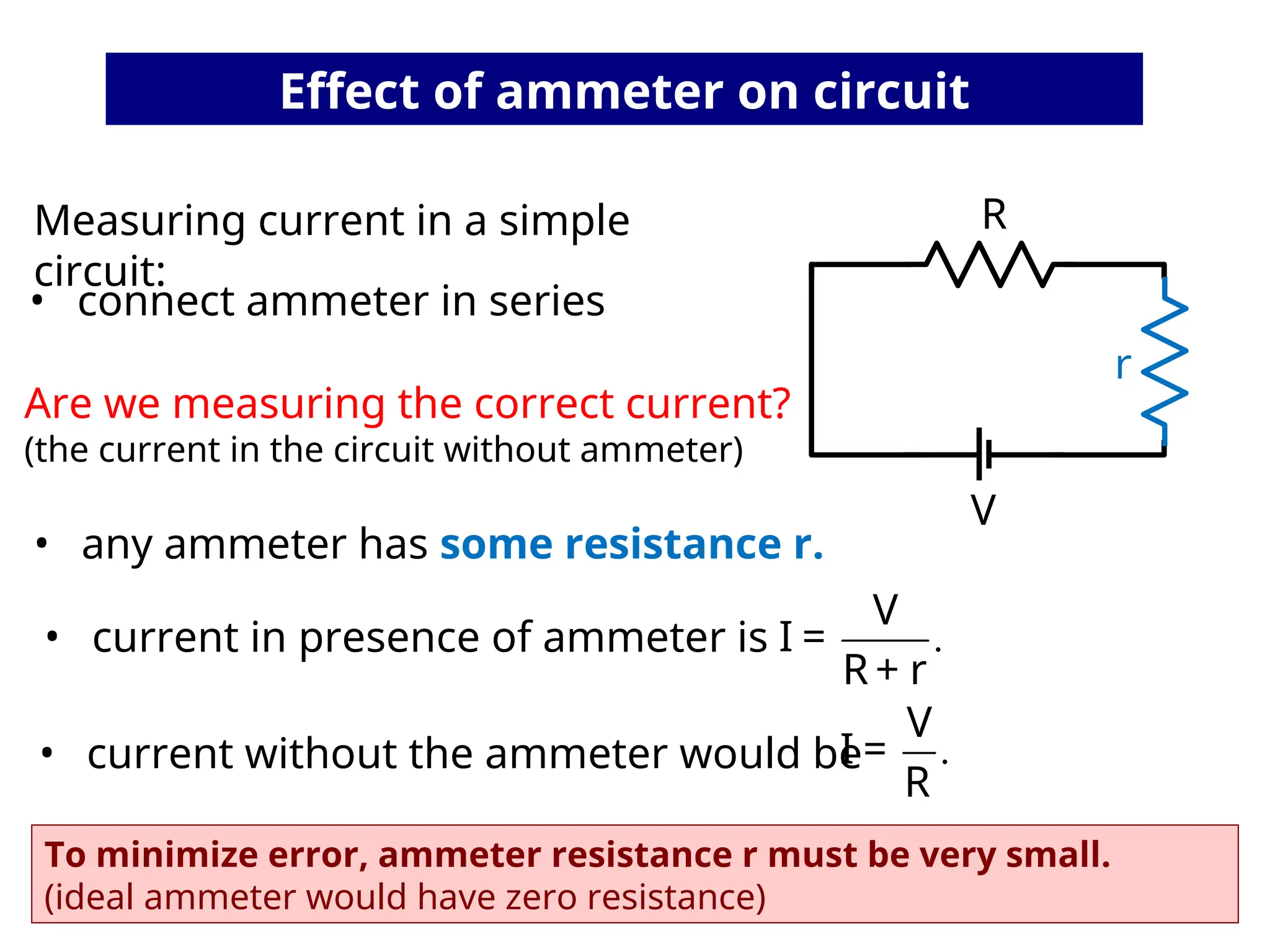
Measuring current in a simple
circuit:
A
• connect ammeter in series
Are we measuring the correct current?
(the current in the circuit without ammeter)
4.
• current withoutthe ammeter would be
V
R
.
V
I =
R
Measuring current in a simple
circuit:
.
V
I =
R + r
To minimize error, ammeter resistance r must be very small.
(ideal ammeter would have zero resistance)
• any ammeter has some resistance r.
r
• connect ammeter in series
Are we measuring the correct current?
(the current in the circuit without ammeter)
• current in presence of ammeter is
Effect of ammeter on circuit
5.
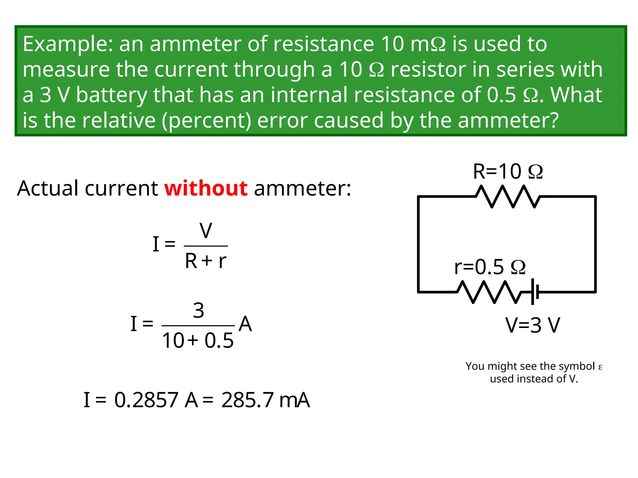
Example: an ammeterof resistance 10 m is used to
measure the current through a 10 resistor in series with
a 3 V battery that has an internal resistance of 0.5 . What
is the relative (percent) error caused by the ammeter?
V=3 V
R=10
r=0.5
Actual current without ammeter:
V
I =
R + r
3
I = A
10+ 0.5
I = 0.2857 A = 285.7 mA
You might see the symbol
used instead of V.
6.
V=3 V
R=10
r=0.5
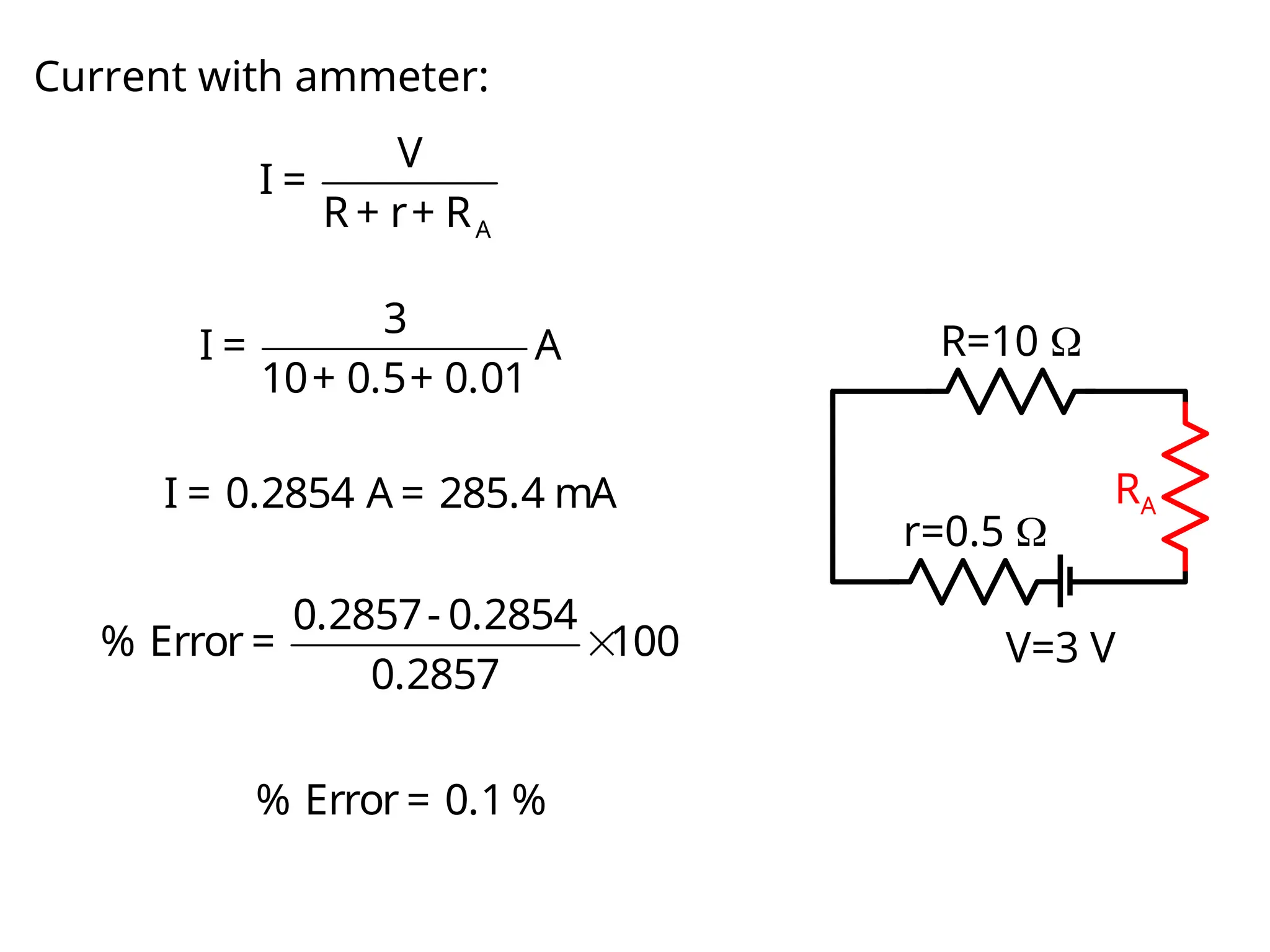
Current with ammeter:
A
V
I =
R + r+ R
3
I = A
10+ 0.5+ 0.01
I = 0.2854 A = 285.4 mA RA
0.2857- 0.2854
% Error = 100
0.2857
% Error = 0.1 %
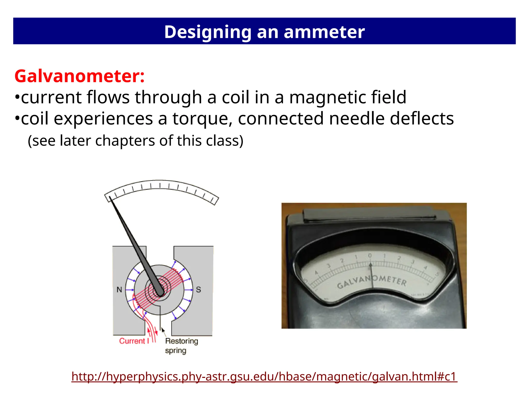
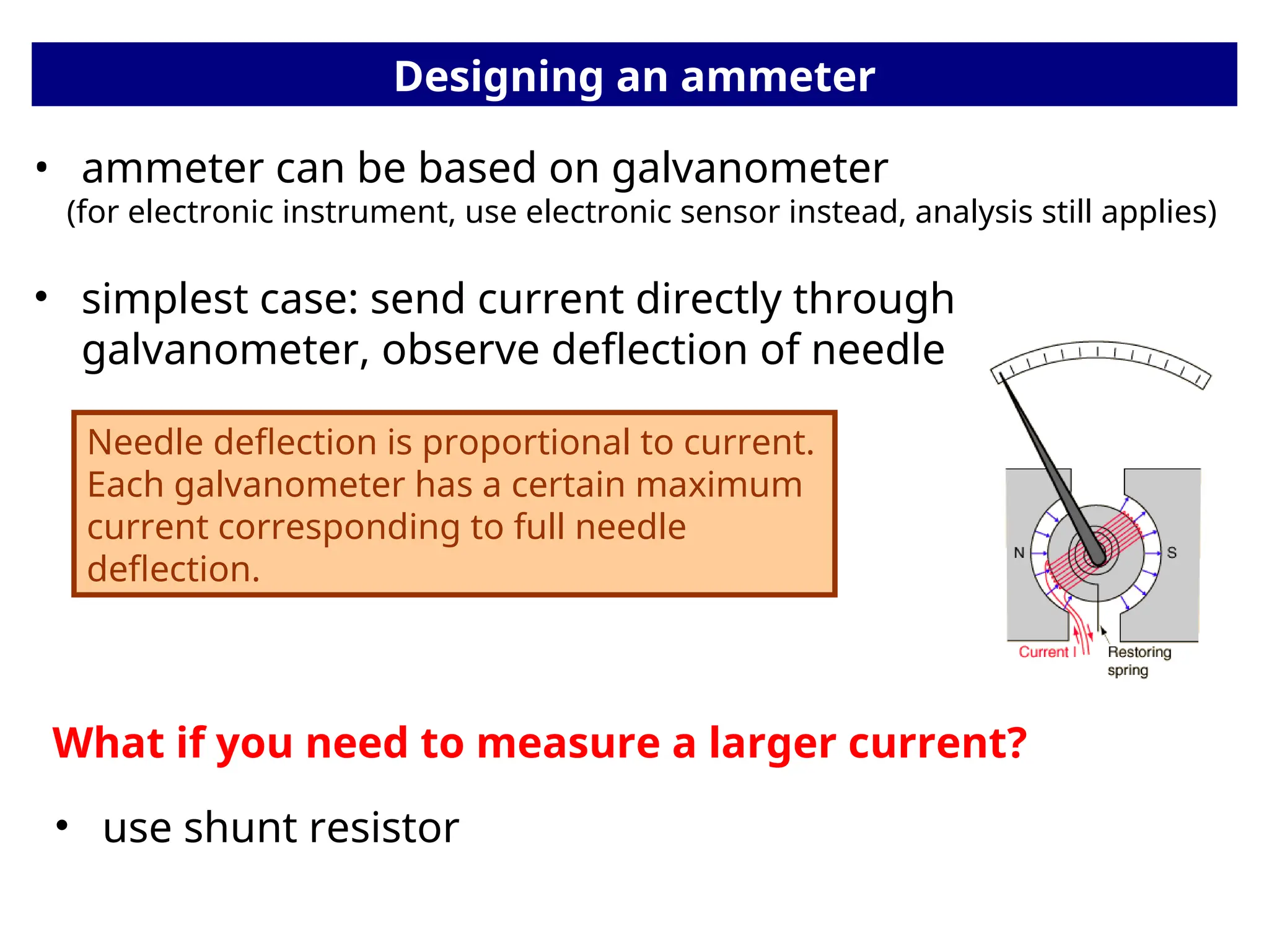
Designing an ammeter
•ammeter can be based on galvanometer
(for electronic instrument, use electronic sensor instead, analysis still applies)
• simplest case: send current directly through
galvanometer, observe deflection of needle
Needle deflection is proportional to current.
Each galvanometer has a certain maximum
current corresponding to full needle
deflection.
What if you need to measure a larger current?
• use shunt resistor
9.
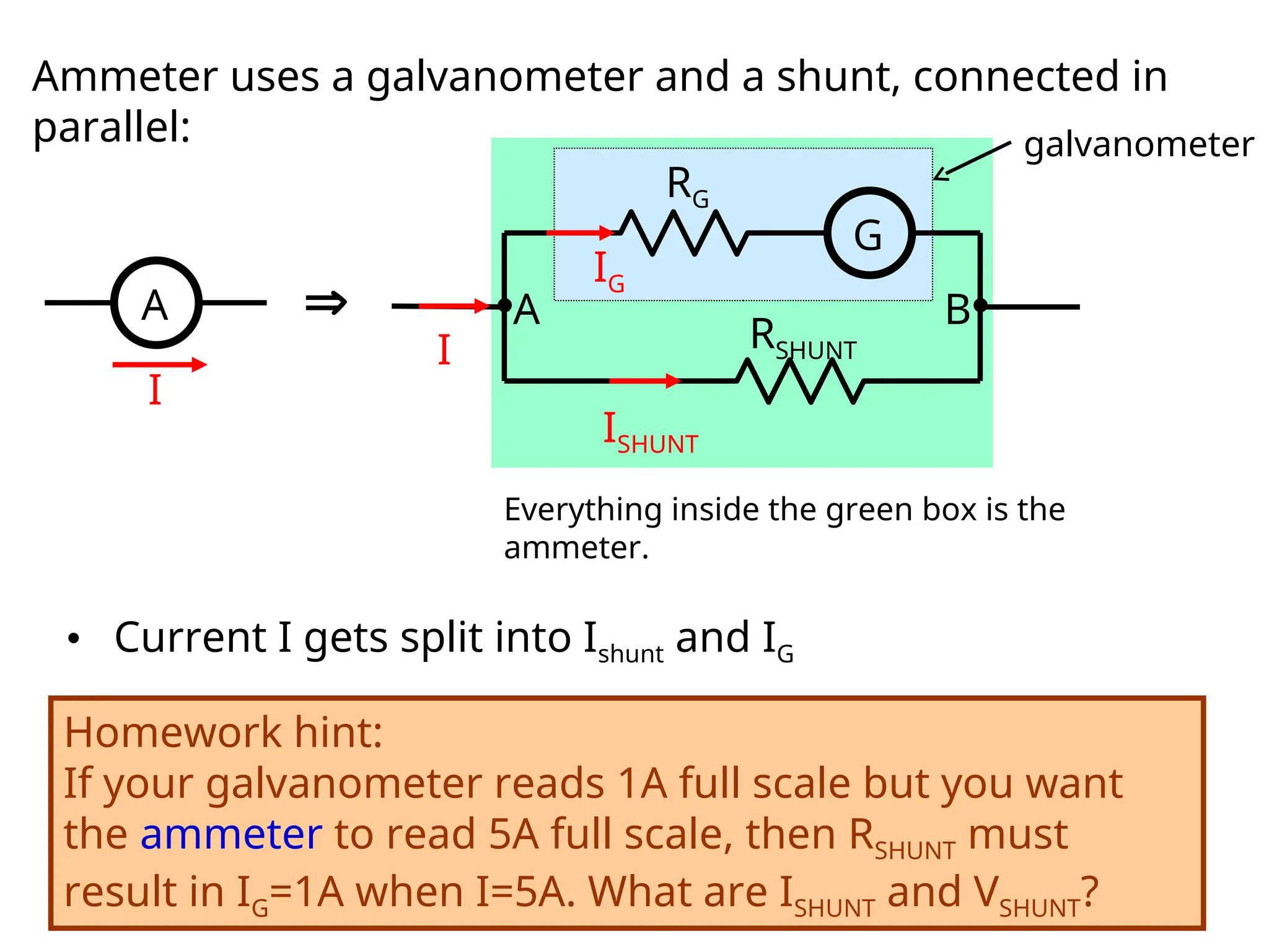
Ammeter uses agalvanometer and a shunt, connected in
parallel:
A
I
Everything inside the green box is the
ammeter.
• Current I gets split into Ishunt and IG
Homework hint:
If your galvanometer reads 1A full scale but you want
the ammeter to read 5A full scale, then RSHUNT must
result in IG=1A when I=5A. What are ISHUNT and VSHUNT?
G
RG
RSHUNT
IG
ISHUNT
I
A B
galvanometer
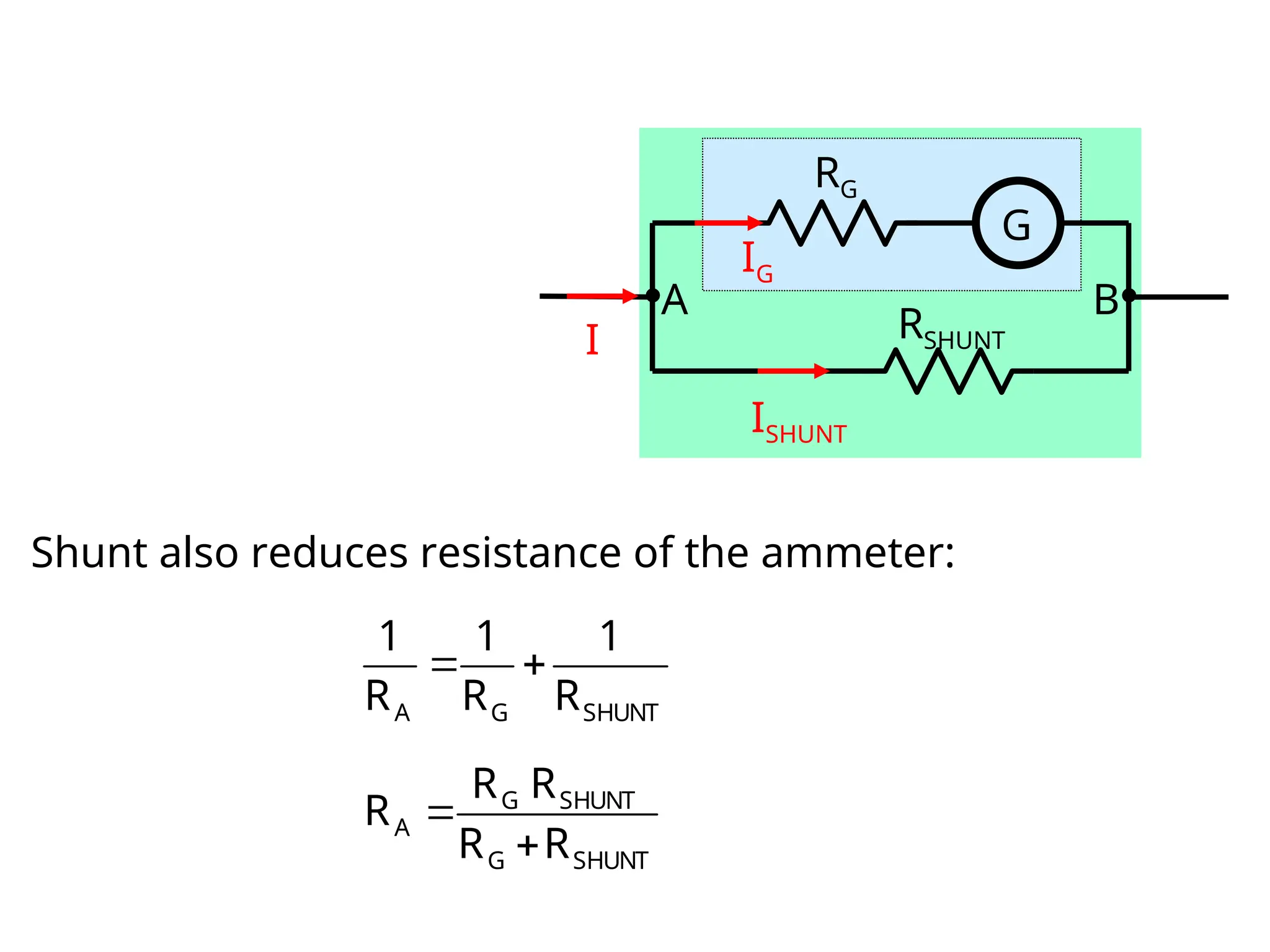
A galvanometer-based ammeteruses a galvanometer and a
shunt, connected in parallel:
G
RG
RS
IG
IS
I
A G S
1 1 1
R R R
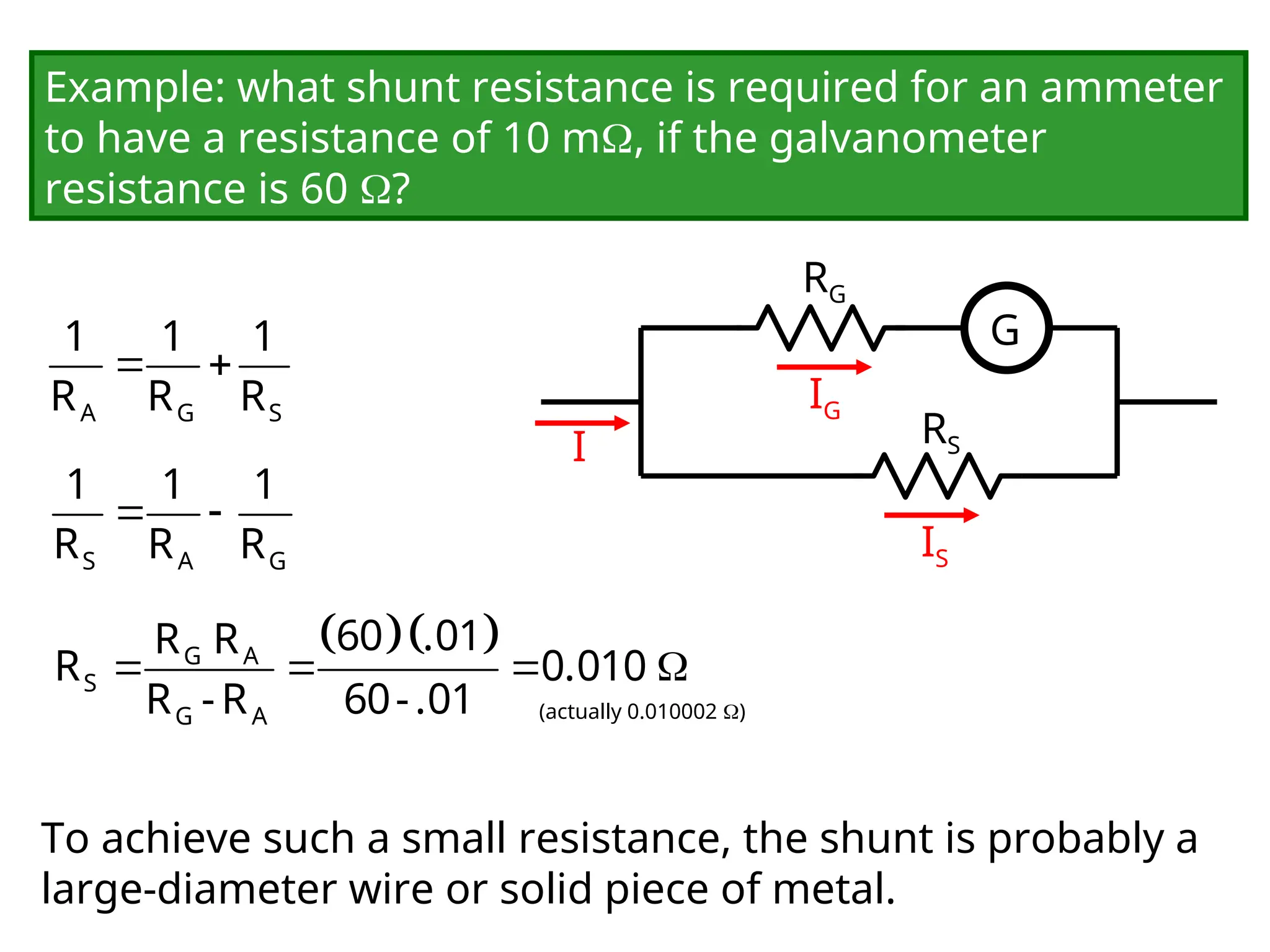
Example: what shunt resistance is required for an ammeter
to have a resistance of 10 m, if the galvanometer
resistance is 60 ?
S A G
1 1 1
R R R
G A
S
G A
60 .01
R R
R 0.010
R -R 60-.01 (actually 0.010002 )
To achieve such a small resistance, the shunt is probably a
large-diameter wire or solid piece of metal.
12.
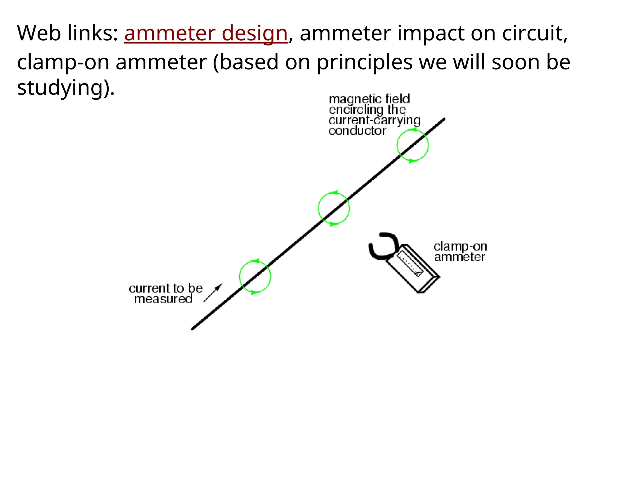
Web links: ammeterdesign, ammeter impact on circuit,
clamp-on ammeter (based on principles we will soon be
studying).
13.
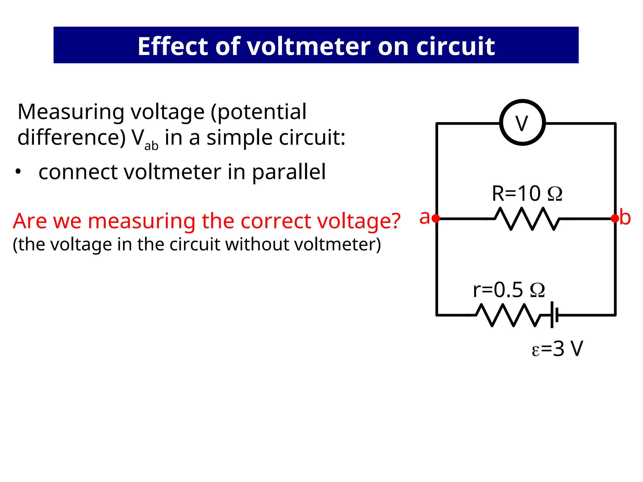
Effect of voltmeteron circuit
Measuring voltage (potential
difference) Vab in a simple circuit:
• connect voltmeter in parallel
Are we measuring the correct voltage?
(the voltage in the circuit without voltmeter)
=3 V
R=10
r=0.5
V
a b
14.
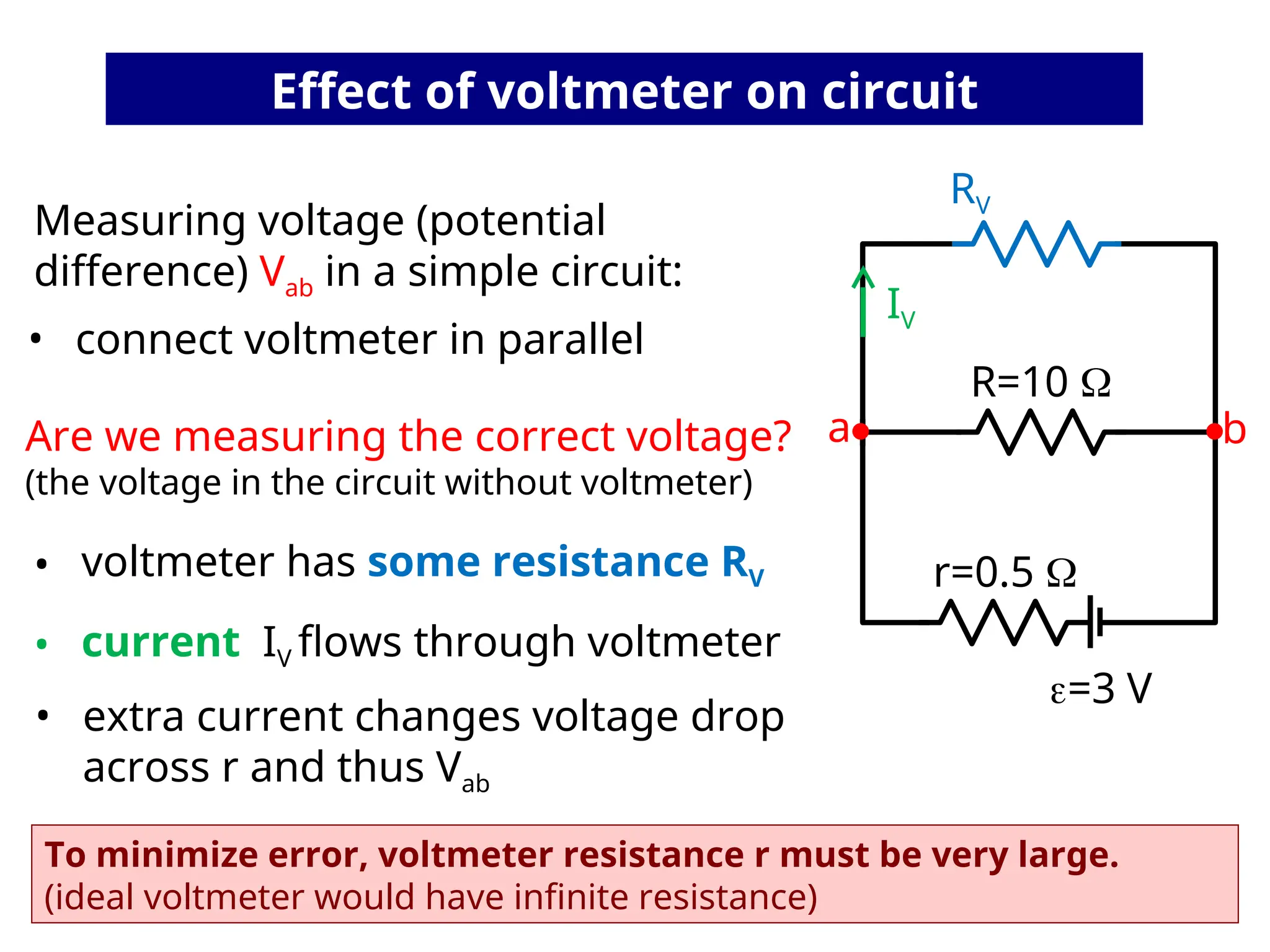
• extra currentchanges voltage drop
across r and thus Vab
To minimize error, voltmeter resistance r must be very large.
(ideal voltmeter would have infinite resistance)
• voltmeter has some resistance RV
• current IV flows through voltmeter
Effect of voltmeter on circuit
Measuring voltage (potential
difference) Vab in a simple circuit:
• connect voltmeter in parallel
Are we measuring the correct voltage?
(the voltage in the circuit without voltmeter)
=3 V
R=10
r=0.5
RV
a b
IV
15.
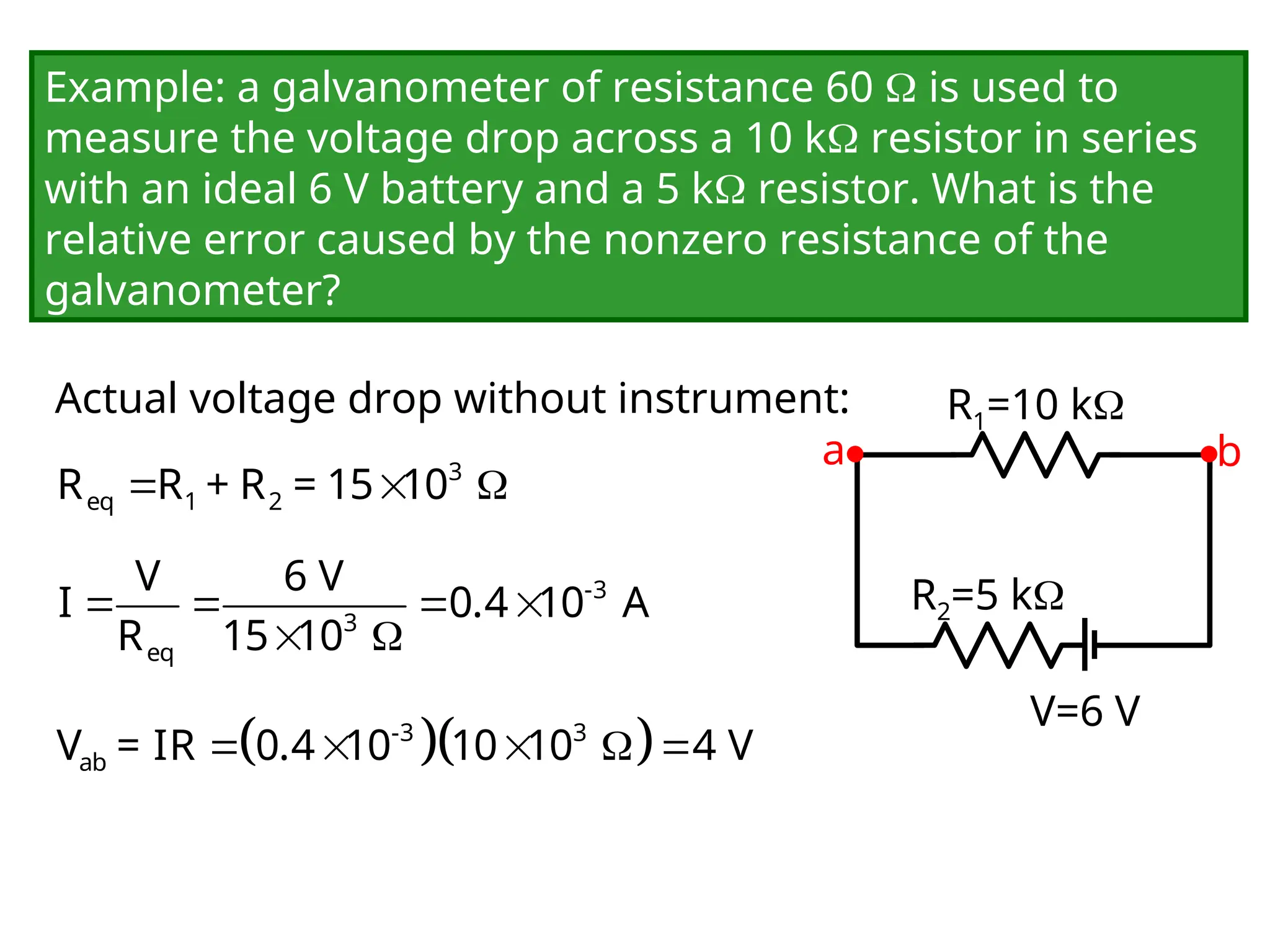
Example: a galvanometerof resistance 60 is used to
measure the voltage drop across a 10 k resistor in series
with an ideal 6 V battery and a 5 k resistor. What is the
relative error caused by the nonzero resistance of the
galvanometer?
Actual voltage drop without instrument:
V=6 V
R1=10 k
R2=5 k
a b
3
eq 1 2
R R + R = 15 10
-3
3
eq
V 6 V
I 0.4 10 A
R 15 10
-3 3
ab
V = IR 0.4 10 10 10 4 V
16.
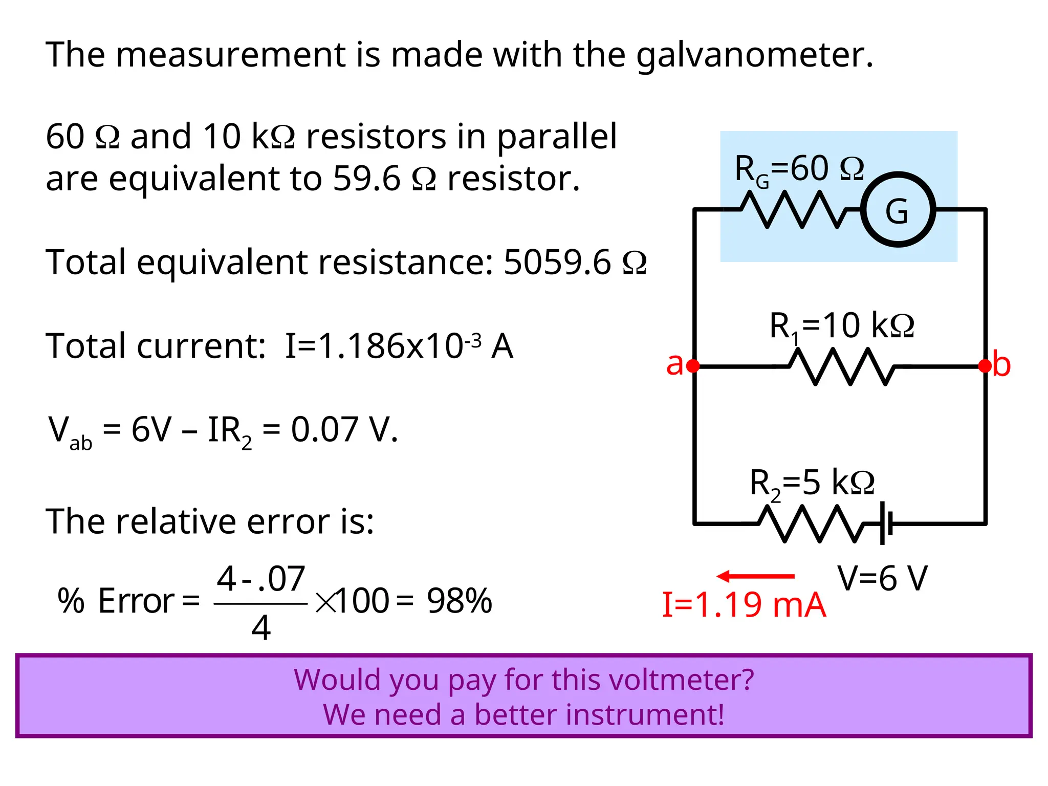
The measurement ismade with the galvanometer.
V=6 V
R1=10 k
R2=5 k
G
RG=60
a b
60 and 10 k resistors in parallel
are equivalent to 59.6 resistor.
Total equivalent resistance: 5059.6
Total current: I=1.186x10⁻³
A
I=1.19 mA
Vab = 6V – IR2 = 0.07 V.
The relative error is:
4-.07
% Error = 100= 98%
4
Would you pay for this voltmeter?
Would you pay for this voltmeter?
We need a better instrument!
17.
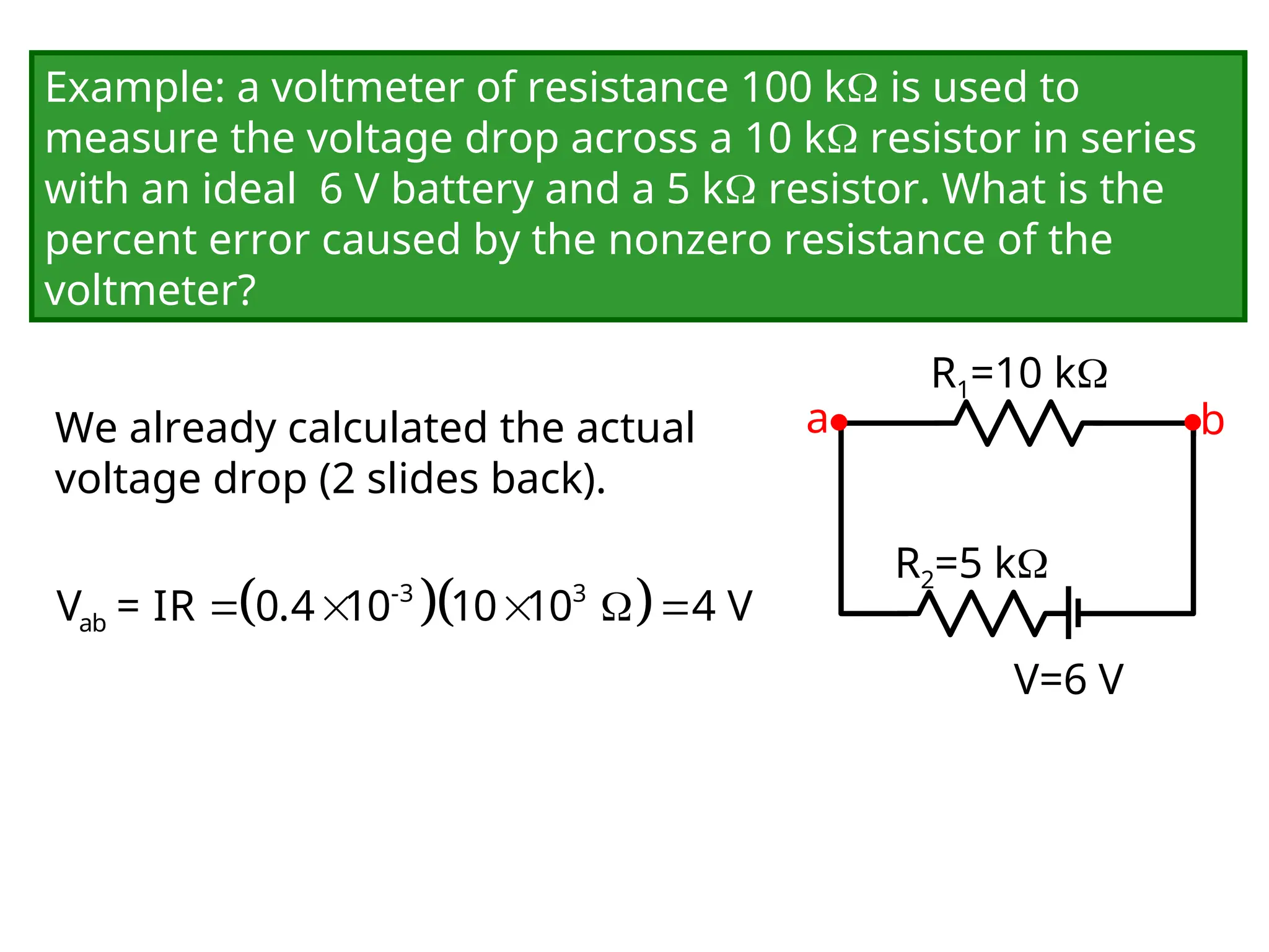
Example: a voltmeterof resistance 100 k is used to
measure the voltage drop across a 10 k resistor in series
with an ideal 6 V battery and a 5 k resistor. What is the
percent error caused by the nonzero resistance of the
voltmeter?
We already calculated the actual
voltage drop (2 slides back).
V=6 V
R1=10 k
R2=5 k
a b
-3 3
ab
V = IR 0.4 10 10 10 4 V
18.
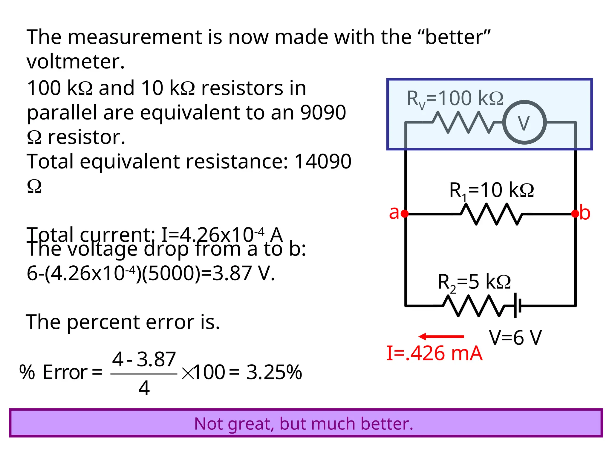
The measurement isnow made with the “better”
voltmeter.
V=6 V
R1=10 k
R2=5 k
V
RV=100 k
a b
100 k and 10 k resistors in
parallel are equivalent to an 9090
resistor.
Total equivalent resistance: 14090
Total current: I=4.26x10⁻⁴
A
I=.426 mA
The voltage drop from a to b:
6-(4.26x10⁻⁴
)(5000)=3.87 V.
The percent error is.
4- 3.87
% Error = 100= 3.25%
4
Not great, but much better.
19.
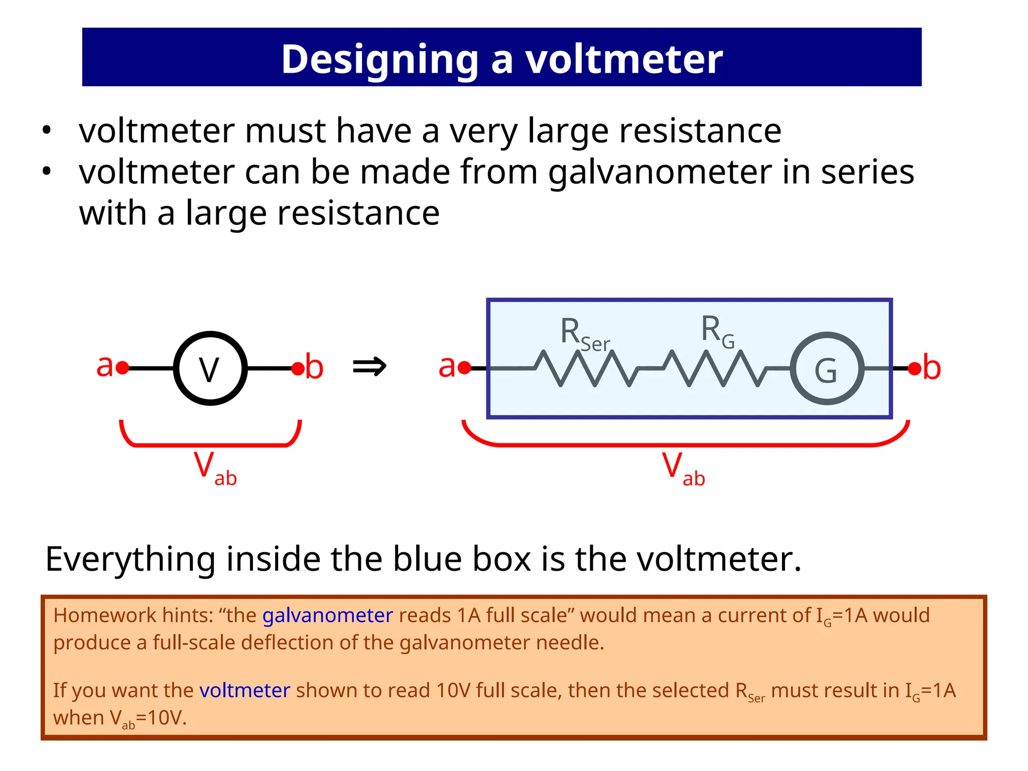
• voltmeter musthave a very large resistance
• voltmeter can be made from galvanometer in series
with a large resistance
V G
RG
RSer
Everything inside the blue box is the voltmeter.
a b
Vab
a b
Vab
Homework hints: “the galvanometer reads 1A full scale” would mean a current of IG=1A would
produce a full-scale deflection of the galvanometer needle.
If you want the voltmeter shown to read 10V full scale, then the selected RSer must result in IG=1A
when Vab=10V.
Homework hints: “the galvanometer reads 1A full scale” would mean a current of IG=1A would
produce a full-scale deflection of the galvanometer needle.
If you want the voltmeter shown to read 10V full scale, then the selected RSer must result in IG=1A
when Vab=10V.
Designing a voltmeter
20.
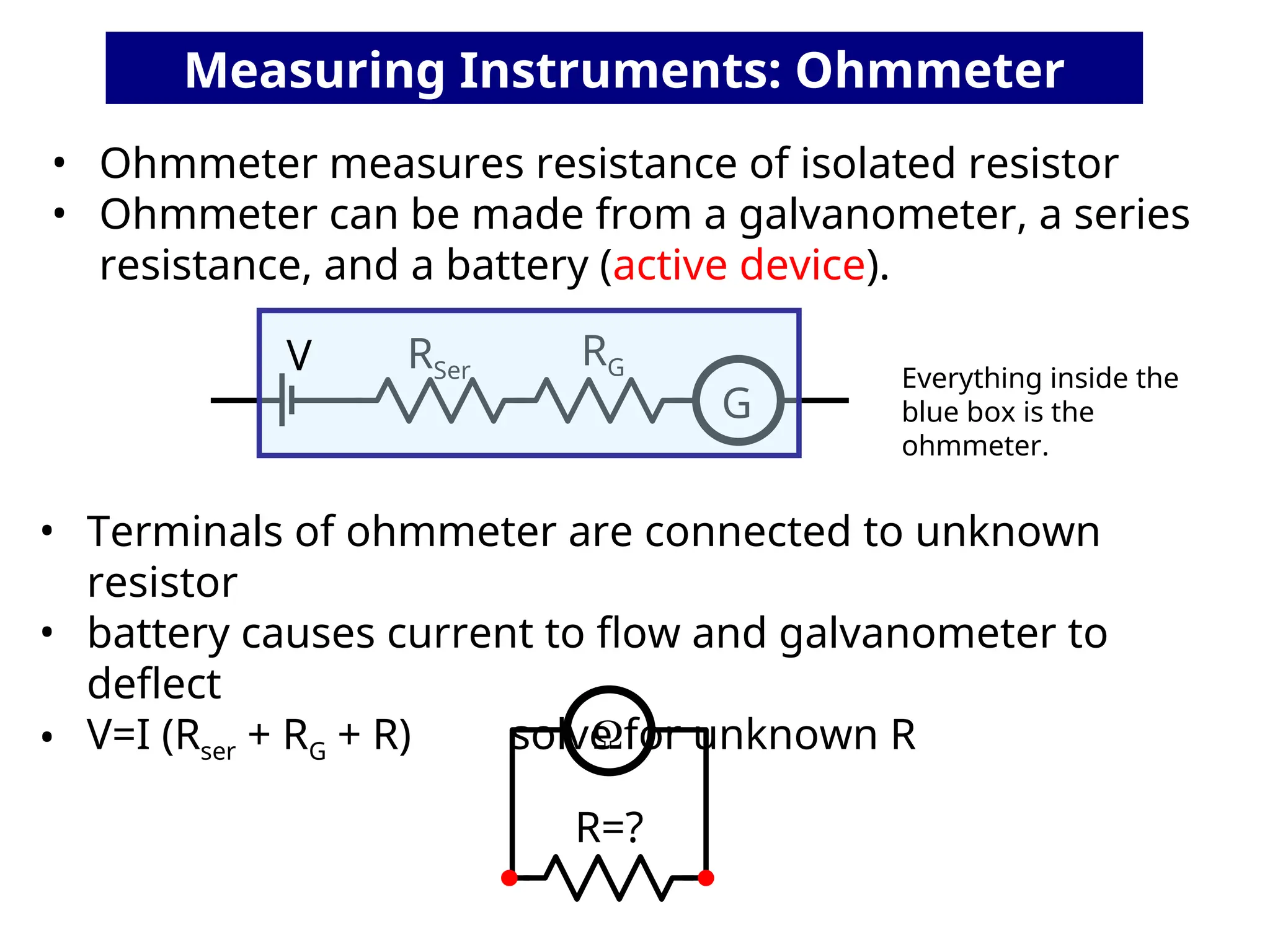
• Ohmmeter measuresresistance of isolated resistor
• Ohmmeter can be made from a galvanometer, a series
resistance, and a battery (active device).
G
RG
RSer
R=?
• Terminals of ohmmeter are connected to unknown
resistor
• battery causes current to flow and galvanometer to
deflect
• V=I (Rser + RG + R) solve for unknown R
Measuring Instruments: Ohmmeter
Everything inside the
blue box is the
ohmmeter.
V
21.
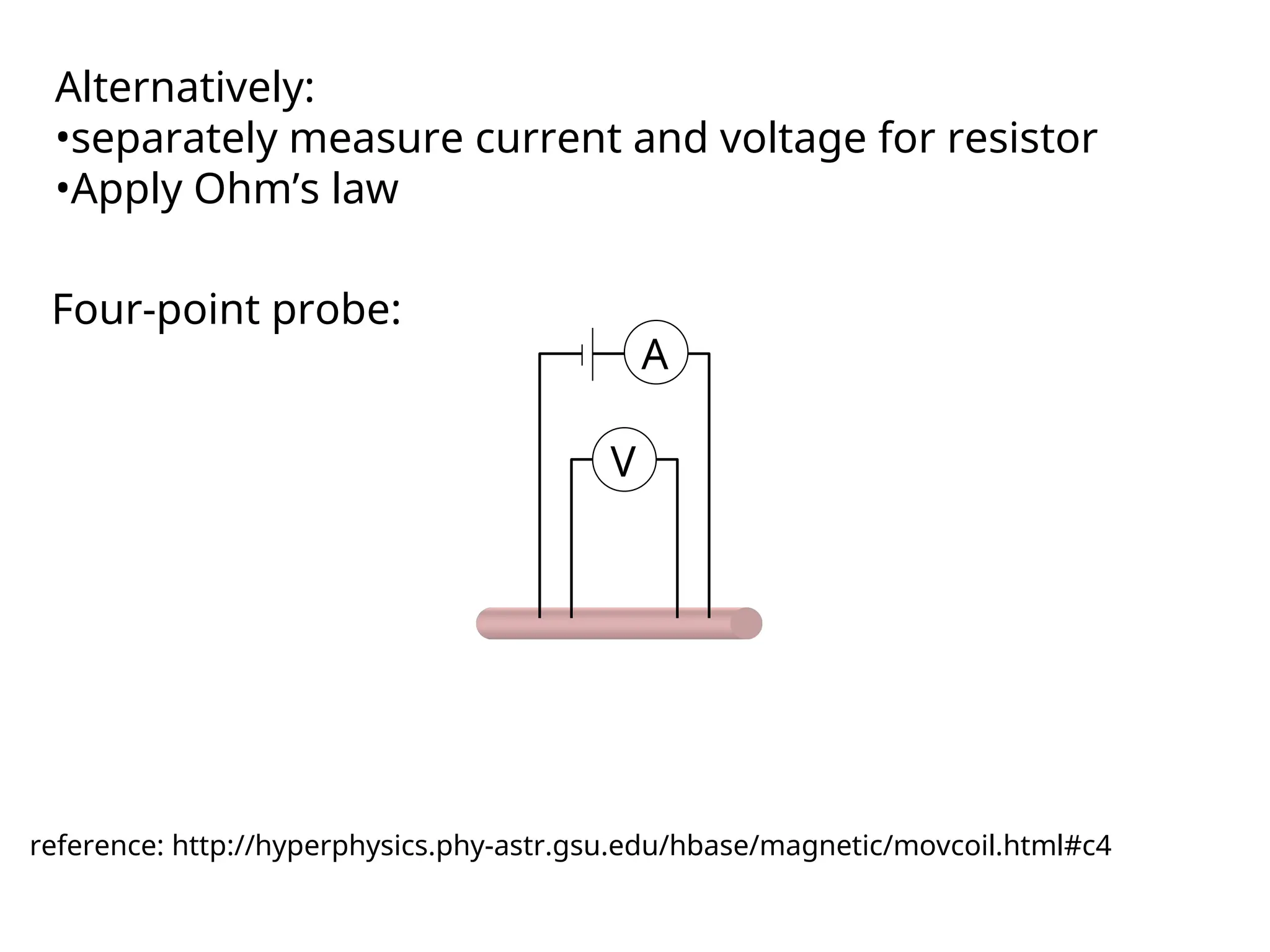
Alternatively:
•separately measure currentand voltage for resistor
•Apply Ohm’s law
Four-point probe:
V
A
reference: http://hyperphysics.phy-astr.gsu.edu/hbase/magnetic/movcoil.html#c4
22.
Today’s agenda:
Measuring Instruments:ammeter, voltmeter, ohmmeter.
You must be able to calculate currents and voltages in circuits that contain “real”
measuring instruments.
RC Circuits.
You must be able to calculate currents and voltages in circuits containing both a
resistor and a capacitor. You must be able to calculate the time constant of an RC
circuit, or use the time constant in other calculations.
23.
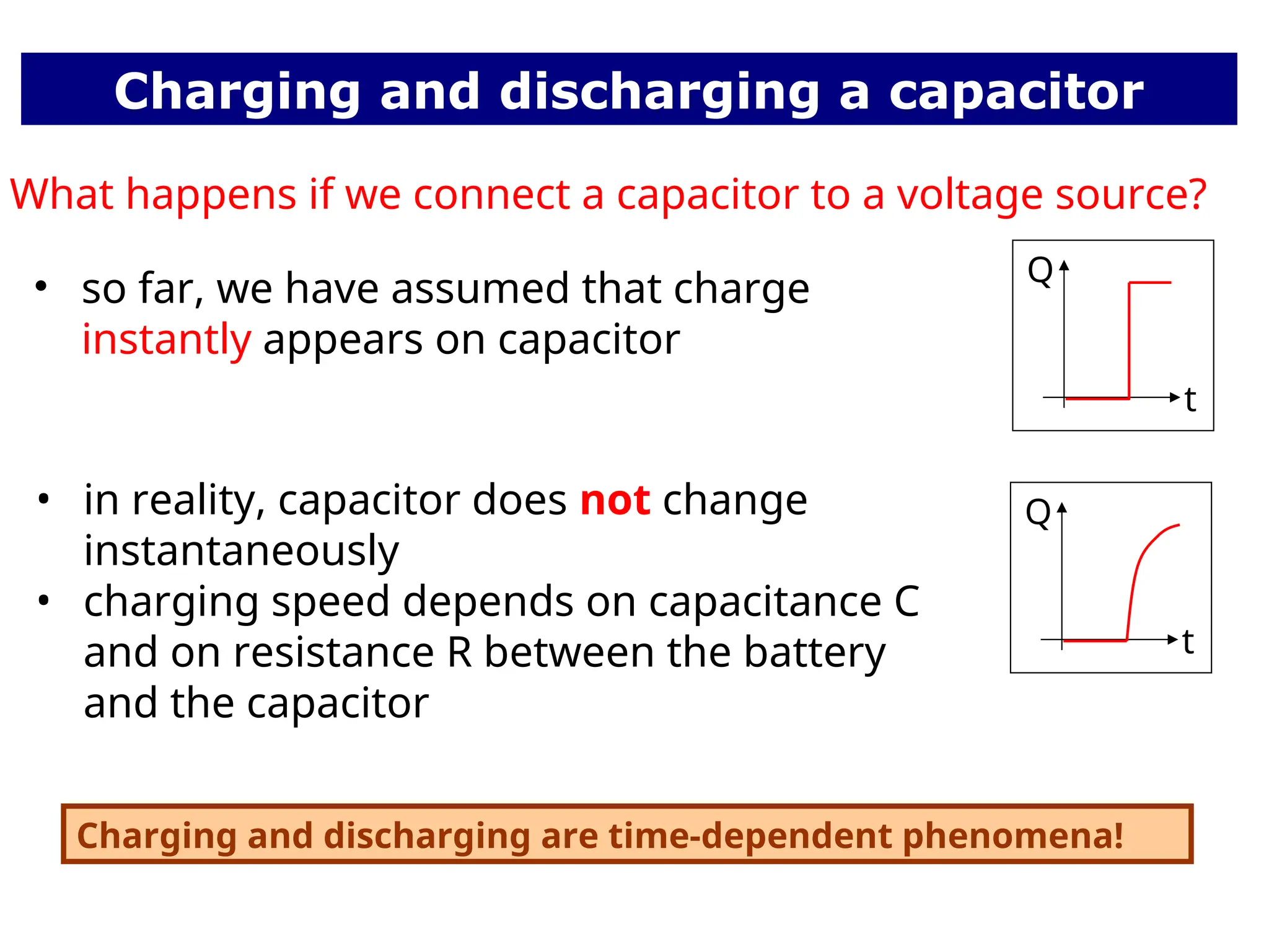
Charging and discharginga capacitor
• so far, we have assumed that charge
instantly appears on capacitor
• in reality, capacitor does not change
instantaneously
• charging speed depends on capacitance C
and on resistance R between the battery
and the capacitor
Q
t
Q
t
What happens if we connect a capacitor to a voltage source?
Charging and discharging are time-dependent phenomena!
24.
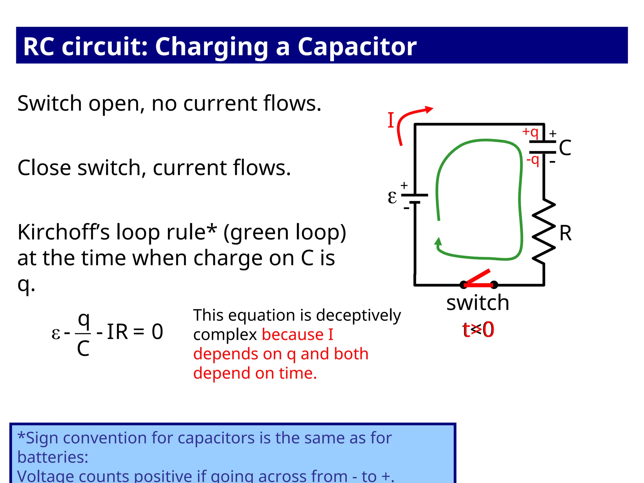
Switch open, nocurrent flows.
RC circuit: Charging a Capacitor
R
switch
C
t<0
Close switch, current flows.
t>0
I
Kirchoff’s loop rule* (green loop)
at the time when charge on C is
q.
*Sign convention for capacitors is the same as for
batteries:
Voltage counts positive if going across from - to +.
ε
q
- - IR = 0
C
This equation is deceptively
complex because I
depends on q and both
depend on time.
-
-
+
+
-q
+q
25.
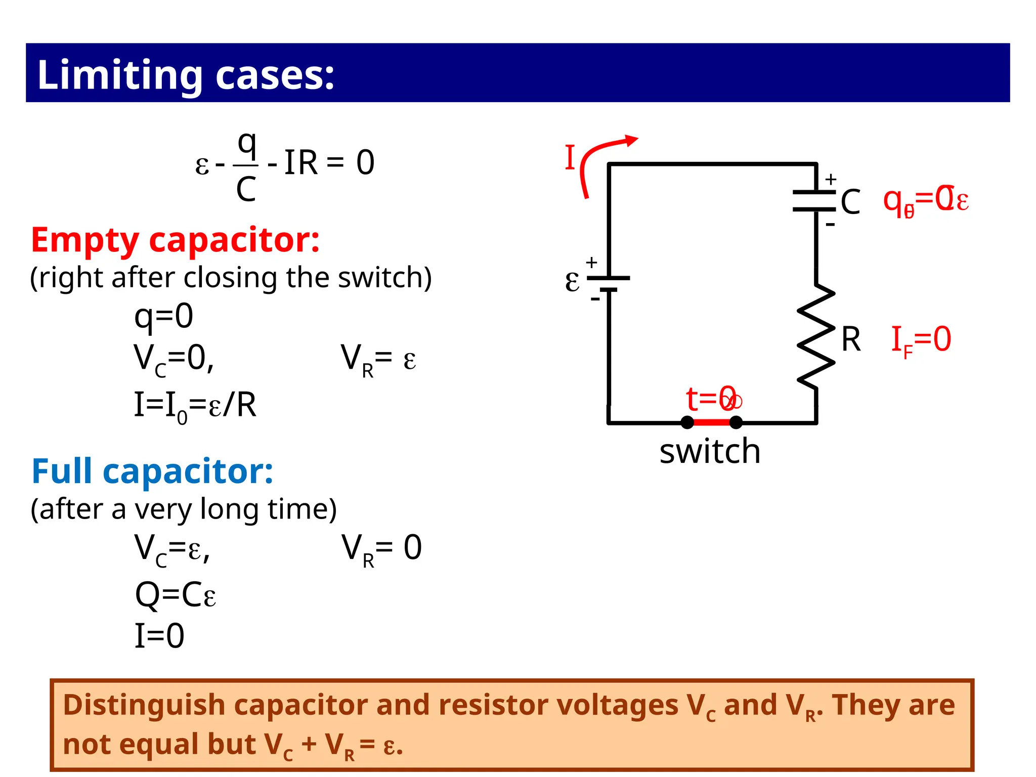
Empty capacitor:
(right afterclosing the switch)
q=0
VC=0, VR=
I=I0=/R
R
switch
C
Full capacitor:
(after a very long time)
VC=, VR= 0
Q=C
I=0
I
ε
q
- - IR = 0
C
-
-
+
+
q0=0
t=0
qF=C
t=
IF=0
Distinguish capacitor and resistor voltages VC and VR. They are
not equal but VC + VR = .
Limiting cases:
26.
ε
q
- - IR= 0
C
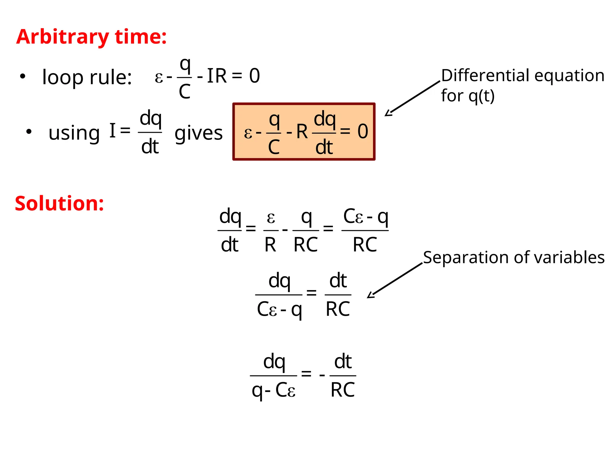
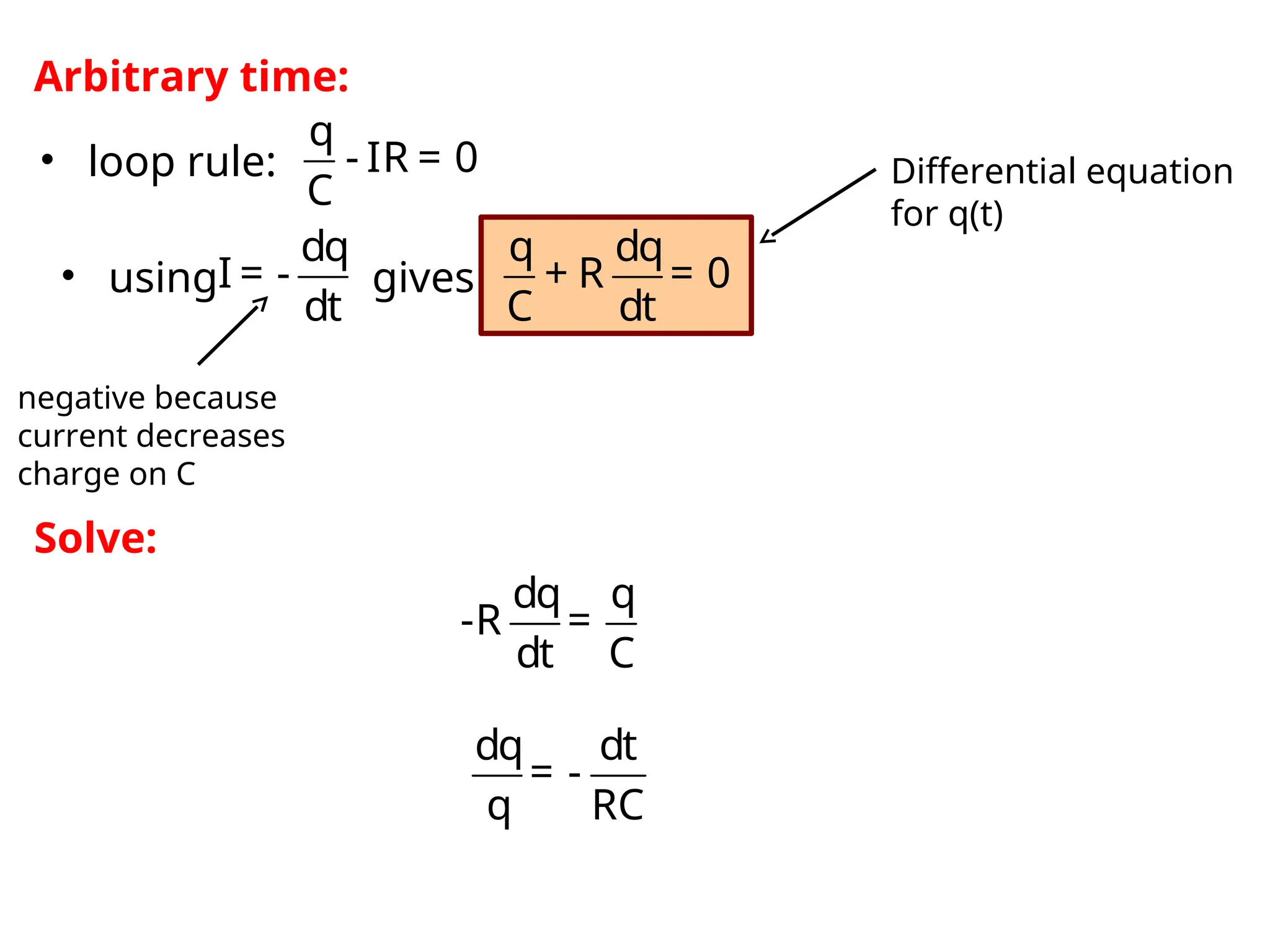
Arbitrary time:
ε ε
dq q C - q
= - =
dt R RC RC
ε
dq dt
=
C - q RC
ε
dq dt
= -
q- C RC
dq
I =
dt
• using gives
• loop rule:
ε
q dq
- -R = 0
C dt
Differential equation
for q(t)
Solution:
Separation of variables
27.
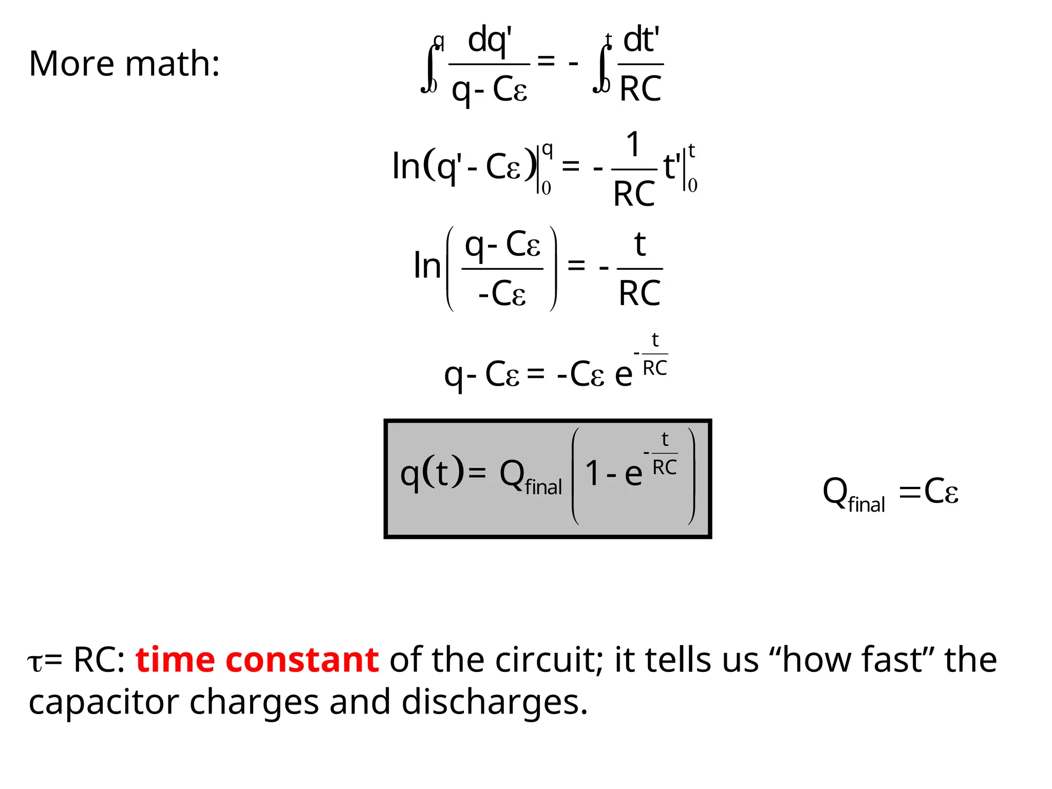
More math: 0ε
q t
0
dq' dt'
= -
q- C RC
0
0
ε
q t
1
ln q'- C = - t'
RC
ε
ε
q- C t
ln = -
-C RC
ε ε
t
-
RC
q- C = -C e
t
-
RC
final
q t = Q 1- e
ε
final
Q C
= RC: time constant of the circuit; it tells us “how fast” the
capacitor charges and discharges.
28.
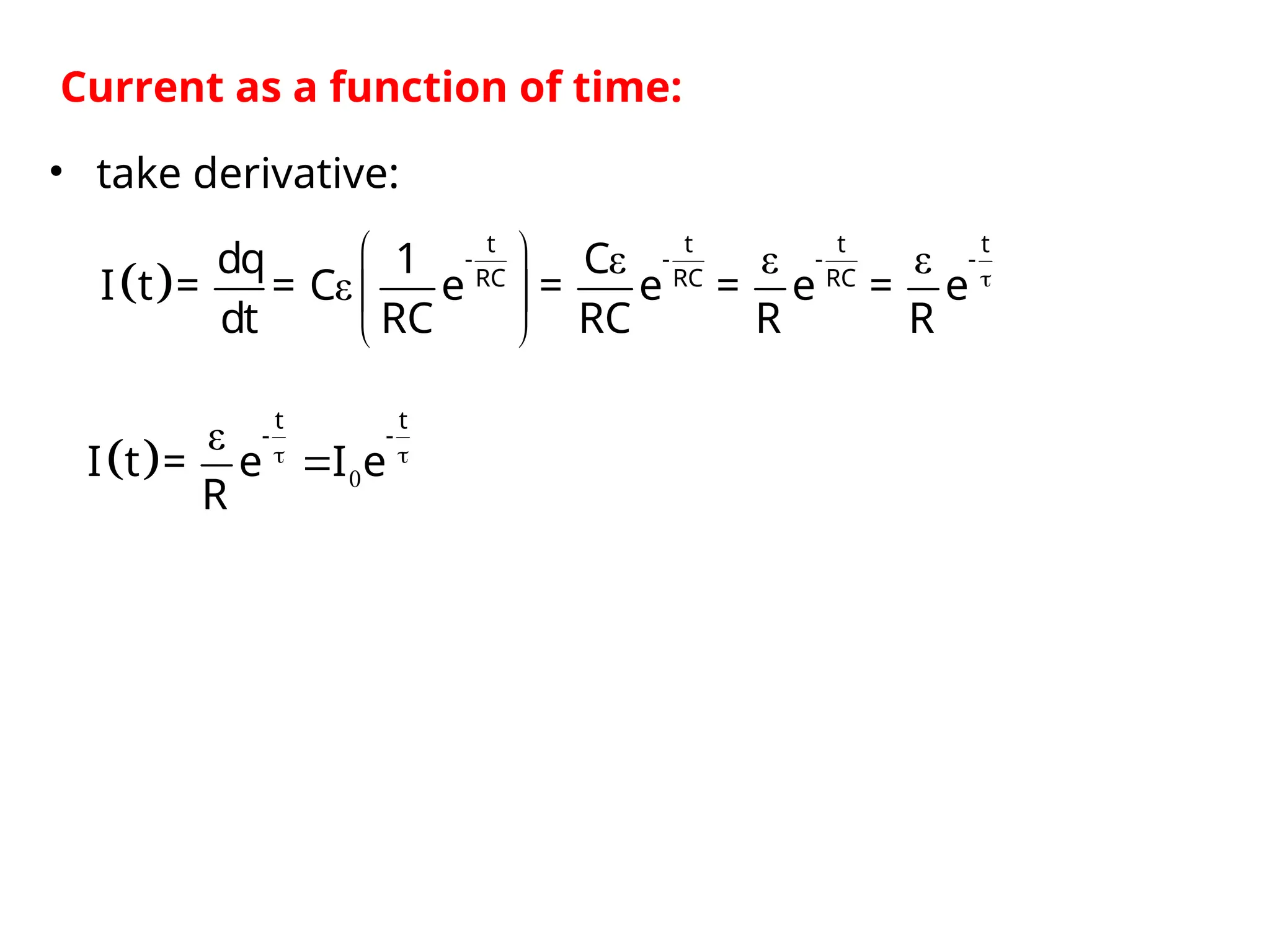
ε εε
ε
t t t t
- - - -
RC RC RC
dq 1 C
I t = = C e = e = e = e
dt RC RC R R
Current as a function of time:
• take derivative:
0
ε
t t
- -
I t = e I e
R
29.
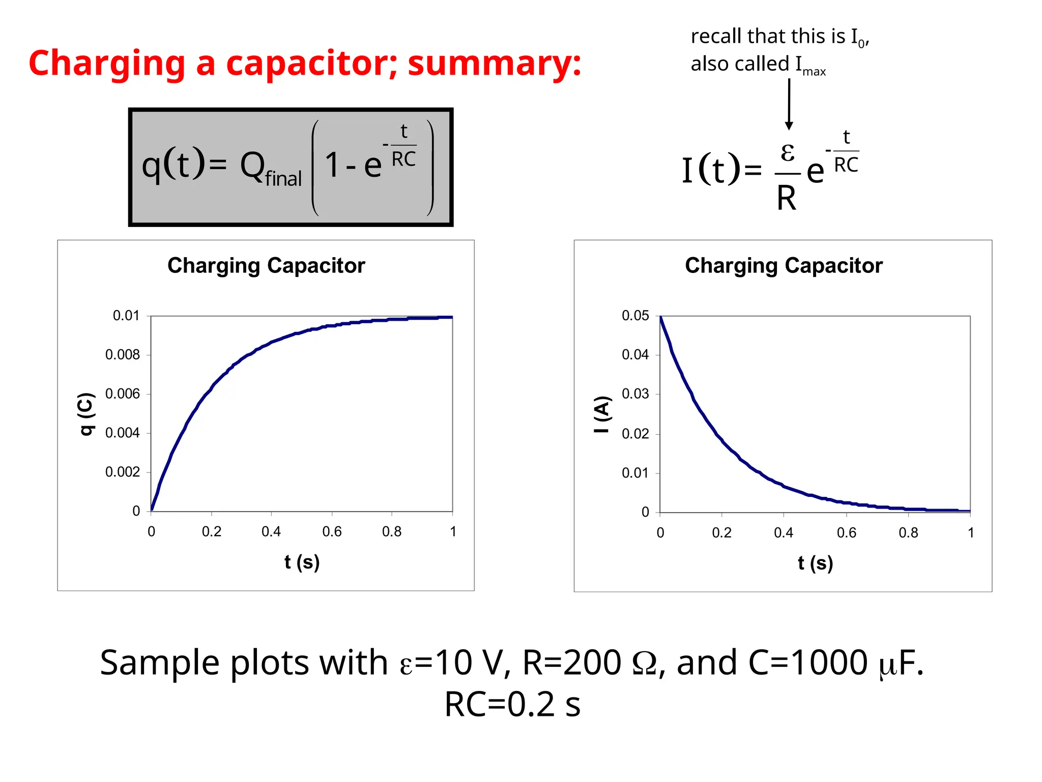
Charging a capacitor;summary:
t
-
RC
final
q t = Q 1- e
ε t
-
RC
I t = e
R
Charging Capacitor
0
0.002
0.004
0.006
0.008
0.01
0 0.2 0.4 0.6 0.8 1
t (s)
q
(C)
Charging Capacitor
0
0.01
0.02
0.03
0.04
0.05
0 0.2 0.4 0.6 0.8 1
t (s)
I
(A)
Sample plots with =10 V, R=200 , and C=1000 F.
RC=0.2 s
recall that this is I0,
also called Imax
30.
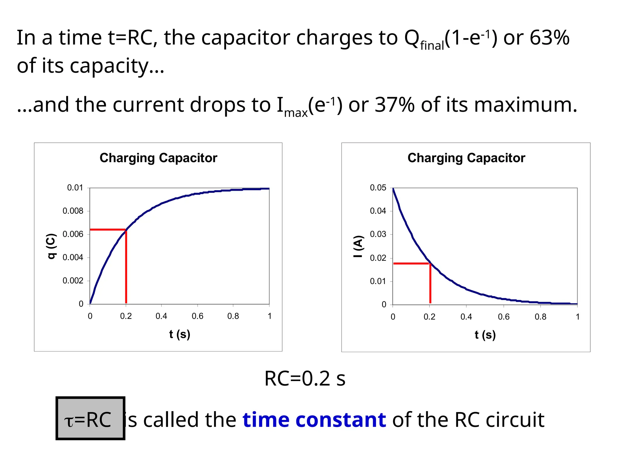
In a timet=RC, the capacitor charges to Qfinal(1-e-1
) or 63%
of its capacity…
Charging Capacitor
0
0.002
0.004
0.006
0.008
0.01
0 0.2 0.4 0.6 0.8 1
t (s)
q
(C)
Charging Capacitor
0
0.01
0.02
0.03
0.04
0.05
0 0.2 0.4 0.6 0.8 1
t (s)
I
(A)
RC=0.2 s
…and the current drops to Imax(e-1
) or 37% of its maximum.
=RC is called the time constant of the RC circuit
31.
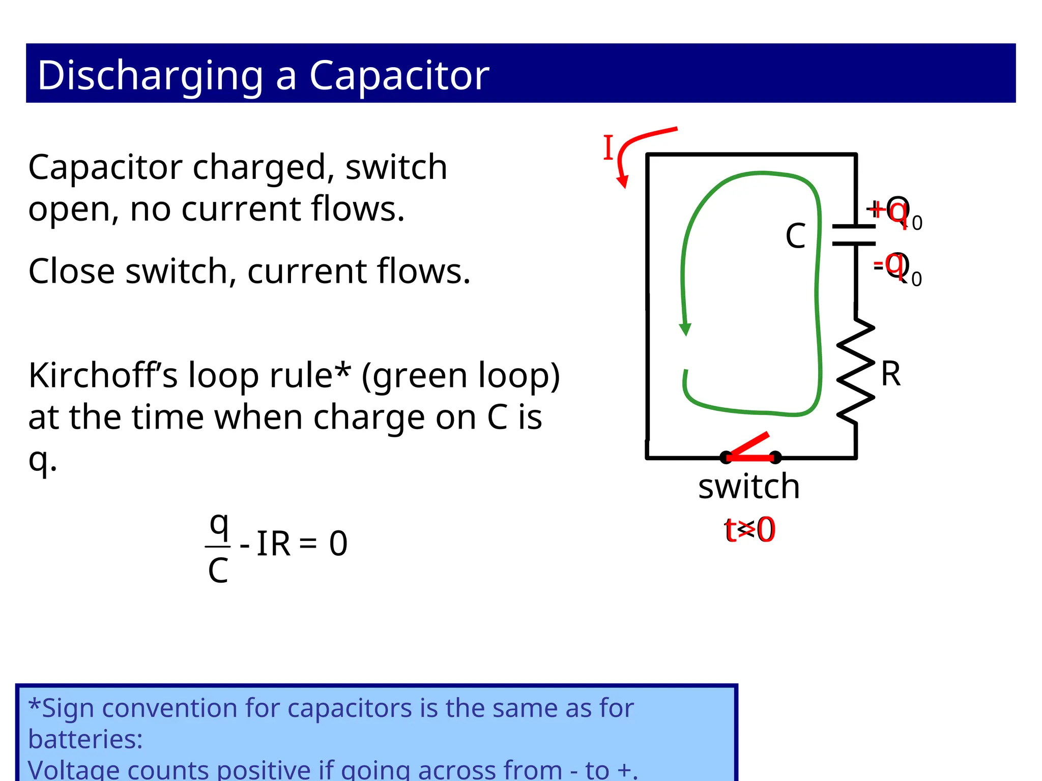
Capacitor charged, switch
open,no current flows.
Discharging a Capacitor
R
switch
C
t<0
Close switch, current flows.
t>0
I
Kirchoff’s loop rule* (green loop)
at the time when charge on C is
q.
q
- IR = 0
C
+Q0
-Q0
-q
+q
*Sign convention for capacitors is the same as for
batteries:
Voltage counts positive if going across from - to +.
32.
q
- IR =0
C
dq dt
= -
q RC
dq q
-R =
dt C
negative because
current decreases
charge on C
Arbitrary time:
dq
I = -
dt
• using gives
• loop rule: Differential equation
for q(t)
q dq
+ R = 0
C dt
Solve:
33.
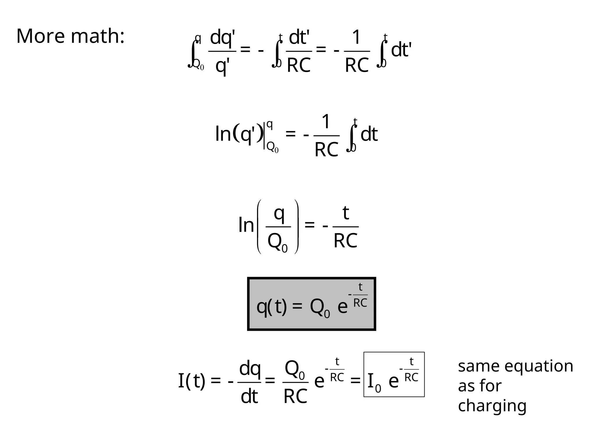
More math:
0
q t t
Q 0 0
dq' dt' 1
= - = - dt'
q' RC RC
0
t
q
Q 0
1
ln q' = - dt
RC
0
q t
ln = -
Q RC
t
-
RC
0
q(t) = Q e
t t
- -
0 RC RC
0
Q
dq
I(t) = - = e = I e
dt RC
same equation
as for
charging
34.
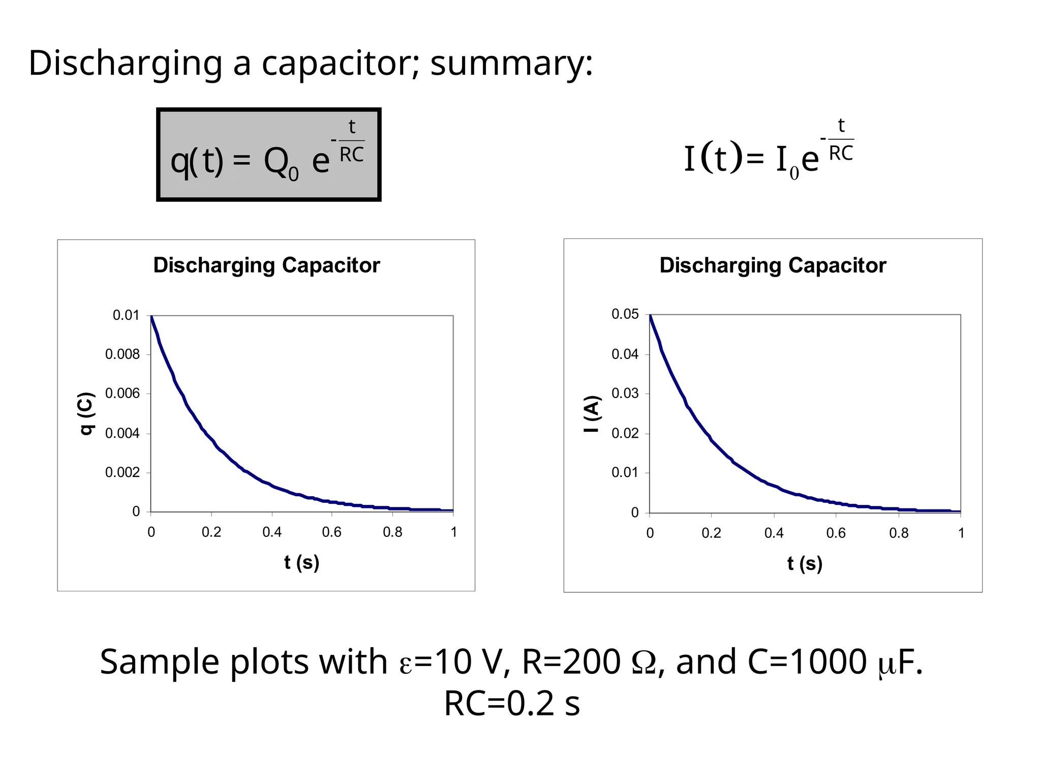
Discharging a capacitor;summary:
0
t
-
RC
I t = I e
Sample plots with =10 V, R=200 , and C=1000 F.
RC=0.2 s
t
-
RC
0
q(t) = Q e
Discharging Capacitor
0
0.002
0.004
0.006
0.008
0.01
0 0.2 0.4 0.6 0.8 1
t (s)
q
(C)
Discharging Capacitor
0
0.01
0.02
0.03
0.04
0.05
0 0.2 0.4 0.6 0.8 1
t (s)
I
(A)
35.
Discharging Capacitor
0
0.01
0.02
0.03
0.04
0.05
0 0.20.4 0.6 0.8 1
t (s)
I
(A)
Discharging Capacitor
0
0.002
0.004
0.006
0.008
0.01
0 0.2 0.4 0.6 0.8 1
t (s)
q
(C)
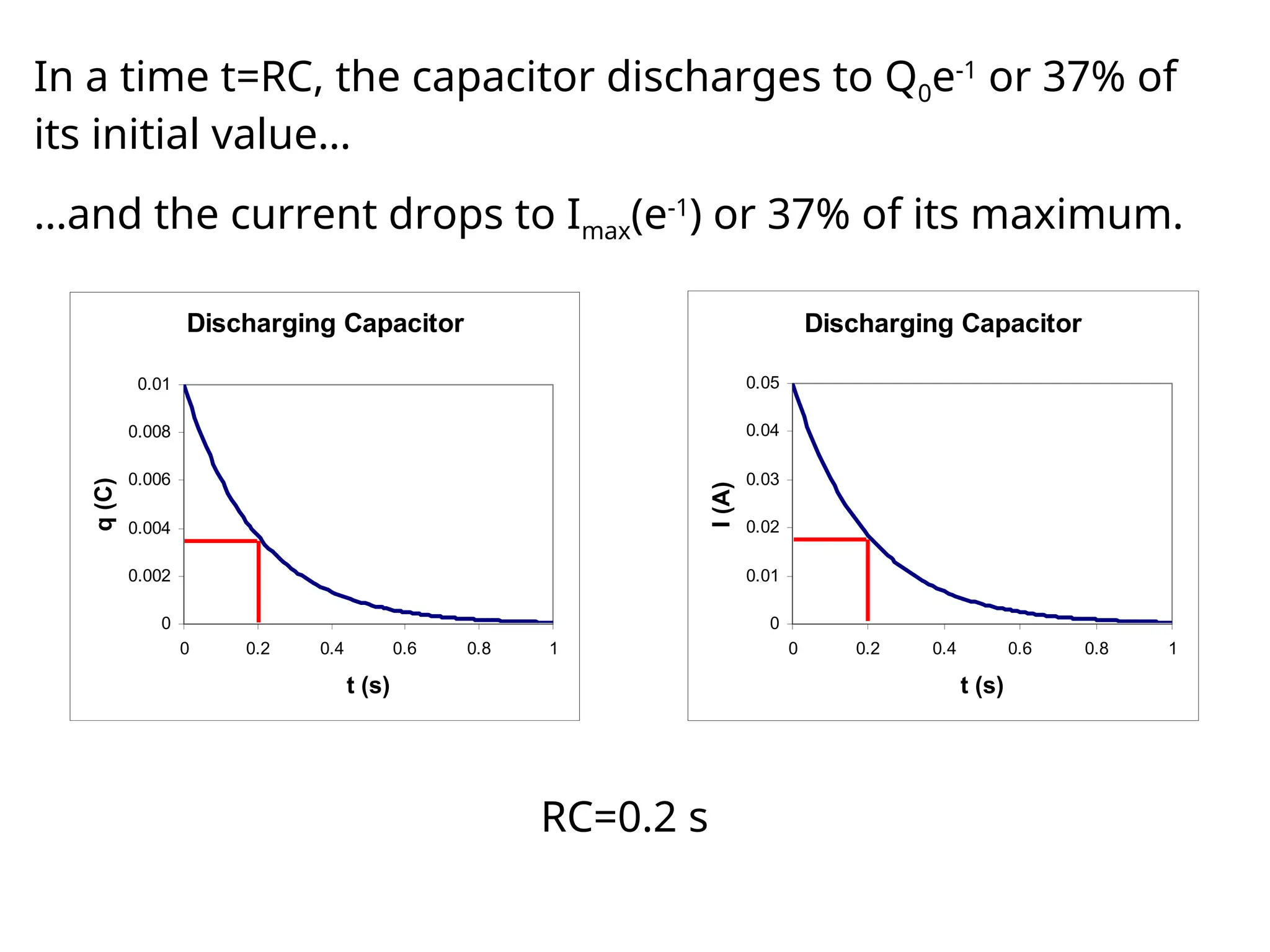
In a time t=RC, the capacitor discharges to Q0e-1
or 37% of
its initial value…
RC=0.2 s
…and the current drops to Imax(e-1
) or 37% of its maximum.
36.
Charging Discharging
Charge Q(t)Q(t) = Qfinal(1-e-t/
) Q(t) = Q0 e-t/
Capacitor voltage VC(t) VC(t) = (1-e-t/
) VC(t) = V0 e-t/
= (Q0/C) e-t/
Resistor voltage VR(t) VR(t) = -VC(t)
= e-t/
VR(t) = VC(t)=V0 e-t/
= (Q0/C) e-t/
Current I(t) I(t) = I0 e-t/
= (/R) e-t/
I(t) = I0 e-t/
= [Q0/(RC)] e-t/
Only the equations for the charge Q(t) are starting equations. You
must be able to derive the other quantities.
=RC
37.
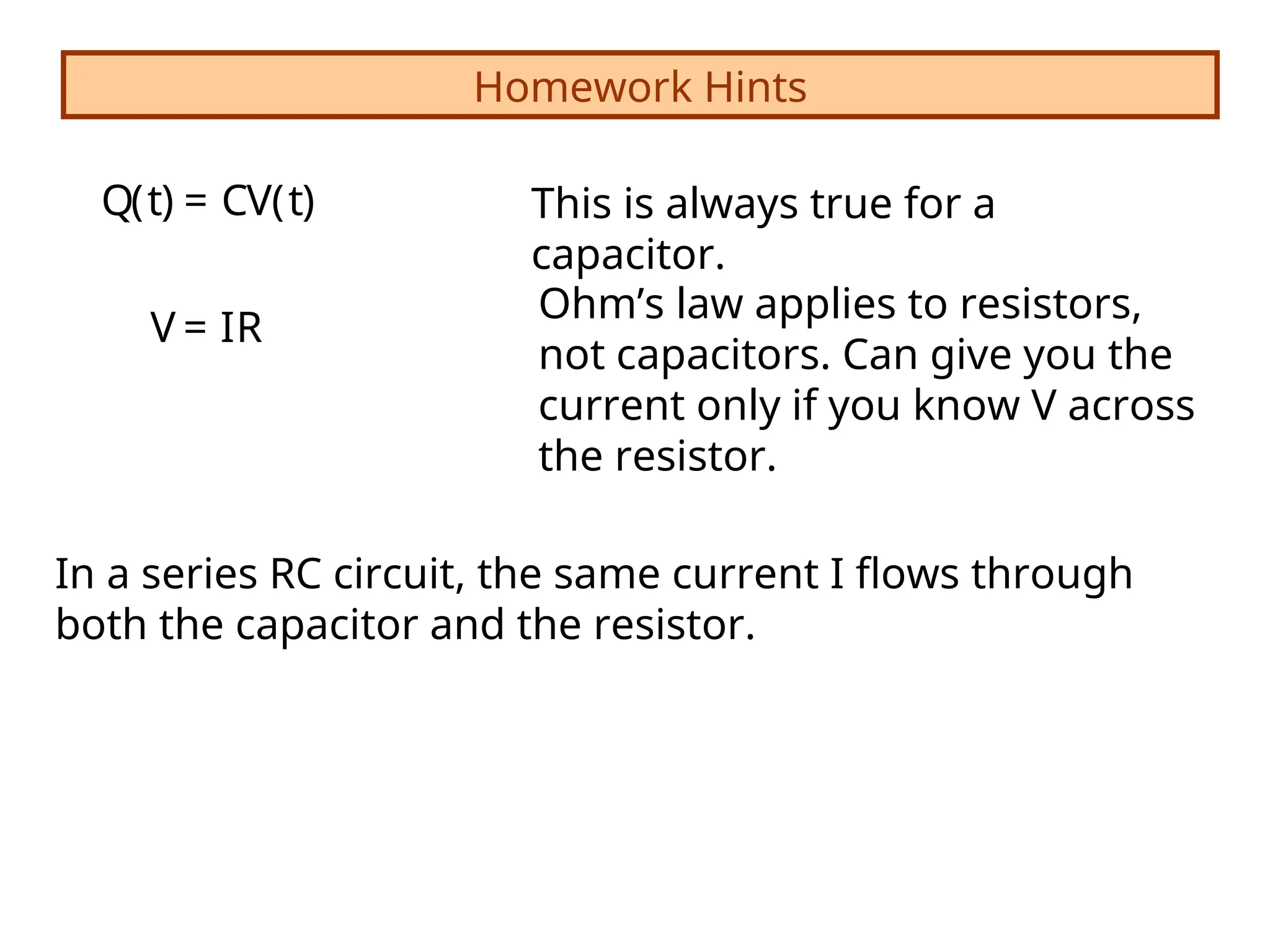
Homework Hints
V =IR
Q(t) = CV(t) This is always true for a
capacitor.
Ohm’s law applies to resistors,
not capacitors. Can give you the
current only if you know V across
the resistor.
In a series RC circuit, the same current I flows through
both the capacitor and the resistor.
38.
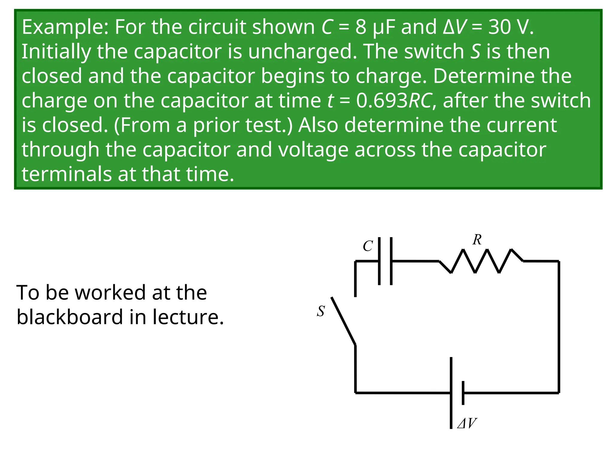
Example: For thecircuit shown C = 8 μF and ΔV = 30 V.
Initially the capacitor is uncharged. The switch S is then
closed and the capacitor begins to charge. Determine the
charge on the capacitor at time t = 0.693RC, after the switch
is closed. (From a prior test.) Also determine the current
through the capacitor and voltage across the capacitor
terminals at that time.
C
ΔV
R
S
To be worked at the
blackboard in lecture.
39.
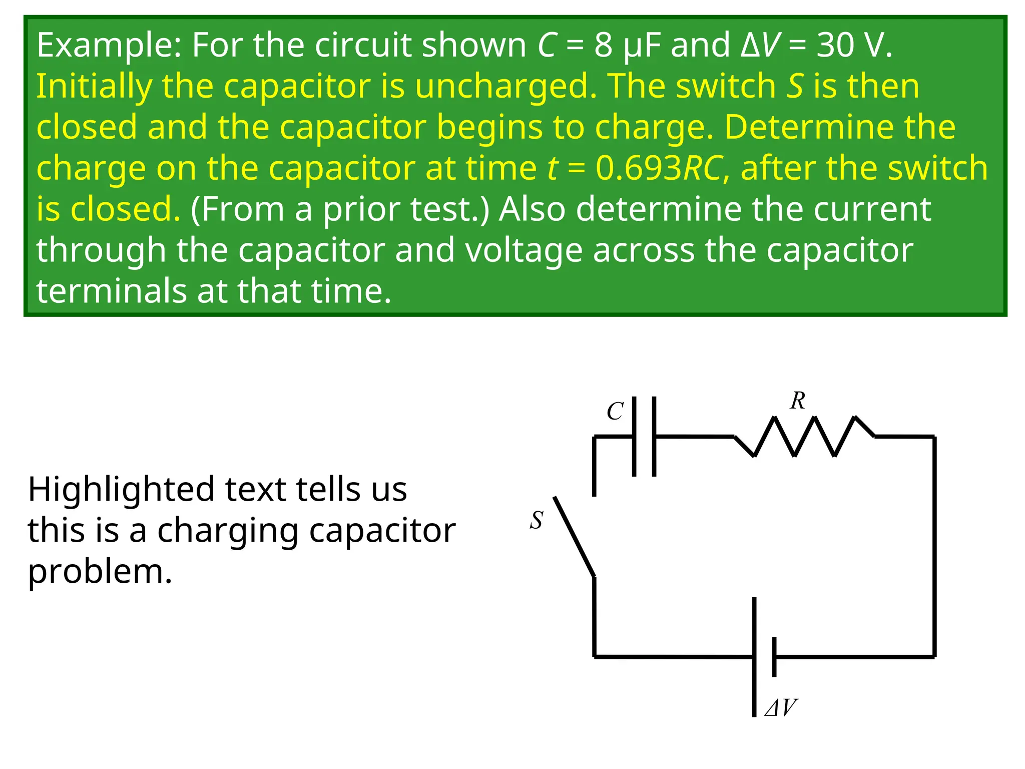
Example: For thecircuit shown C = 8 μF and ΔV = 30 V.
Initially the capacitor is uncharged. The switch S is then
closed and the capacitor begins to charge. Determine the
charge on the capacitor at time t = 0.693RC, after the switch
is closed. (From a prior test.) Also determine the current
through the capacitor and voltage across the capacitor
terminals at that time.
C
ΔV
R
S
Highlighted text tells us
this is a charging capacitor
problem.
40.
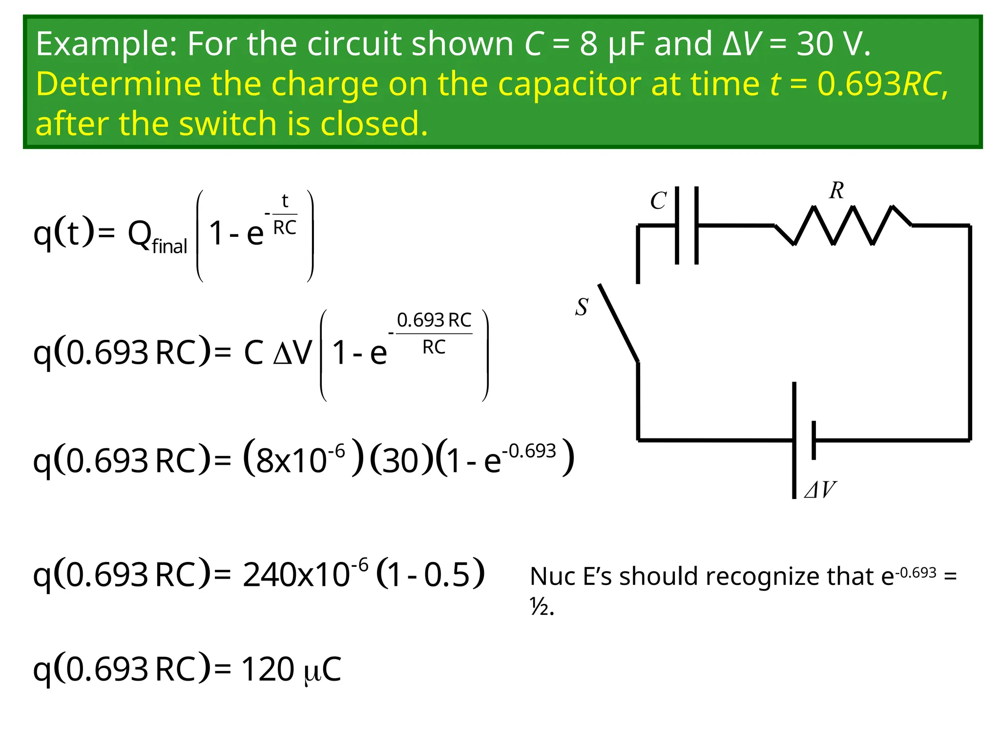
Example: For thecircuit shown C = 8 μF and ΔV = 30 V.
Determine the charge on the capacitor at time t = 0.693RC,
after the switch is closed.
C
ΔV
R
S
t
-
RC
final
q t = Q 1- e
0.693RC
-
RC
q 0.693RC = C V 1- e
-6 -0.693
q 0.693RC = 8x10 30 1- e
-6
q 0.693RC = 240x10 1- 0.5
q 0.693RC = 120 C
Nuc E’s should recognize that e-0.693
=
½.
41.
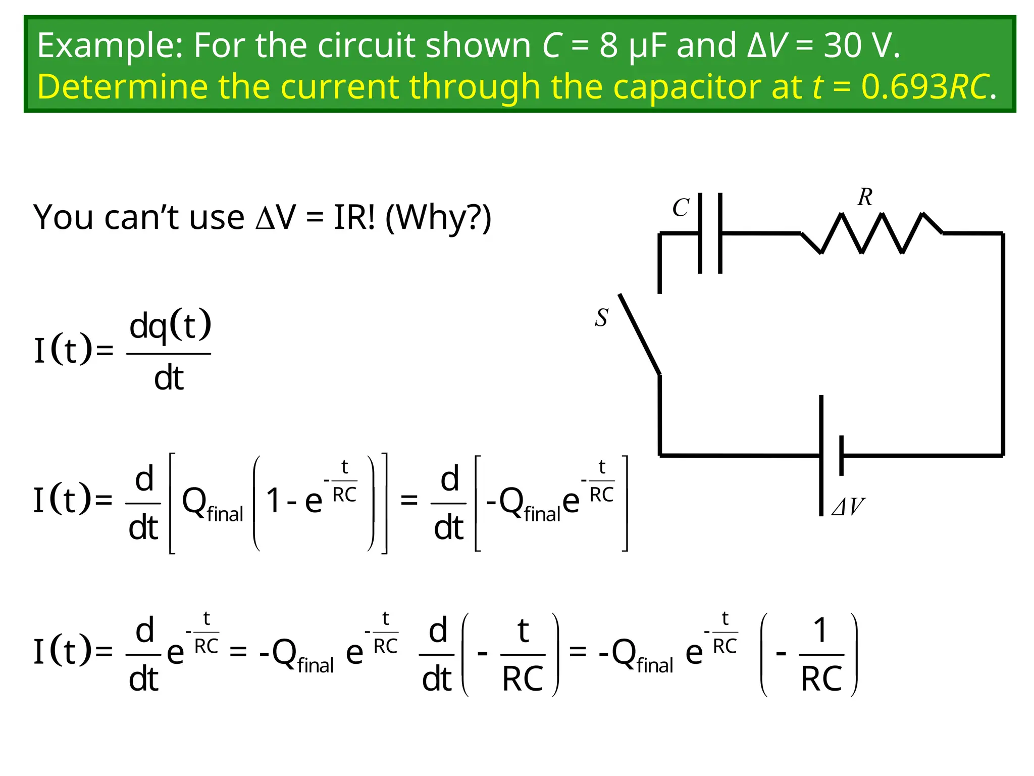
Example: For thecircuit shown C = 8 μF and ΔV = 30 V.
Determine the current through the capacitor at t = 0.693RC.
You can’t use V = IR! (Why?) C
ΔV
R
S
dq t
I t =
dt
t t
- -
RC RC
final final
d d
I t = Q 1- e = -Q e
dt dt
t t t
- - -
RC RC RC
final final
d d t 1
I t = e = -Q e = -Q e
dt dt RC RC
42.
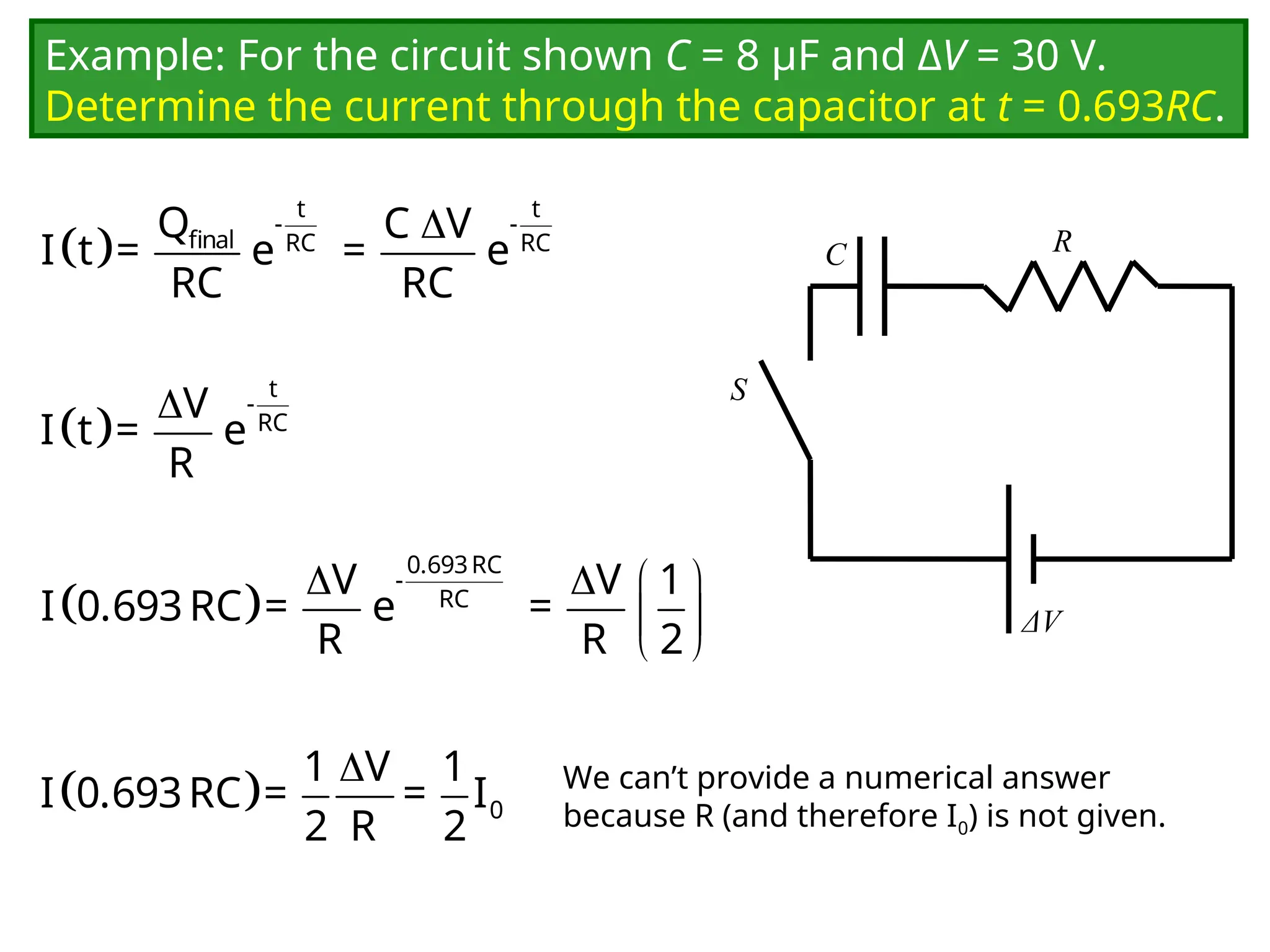
Example: For thecircuit shown C = 8 μF and ΔV = 30 V.
Determine the current through the capacitor at t = 0.693RC.
C
ΔV
R
S
t t
- -
final RC RC
Q C V
I t = e = e
RC RC
t
-
RC
V
I t = e
R
0.693RC
-
RC
V V 1
I 0.693RC = e =
R R 2
0
1 V 1
I 0.693RC = = I
2 R 2
We can’t provide a numerical answer
because R (and therefore I0) is not given.
43.
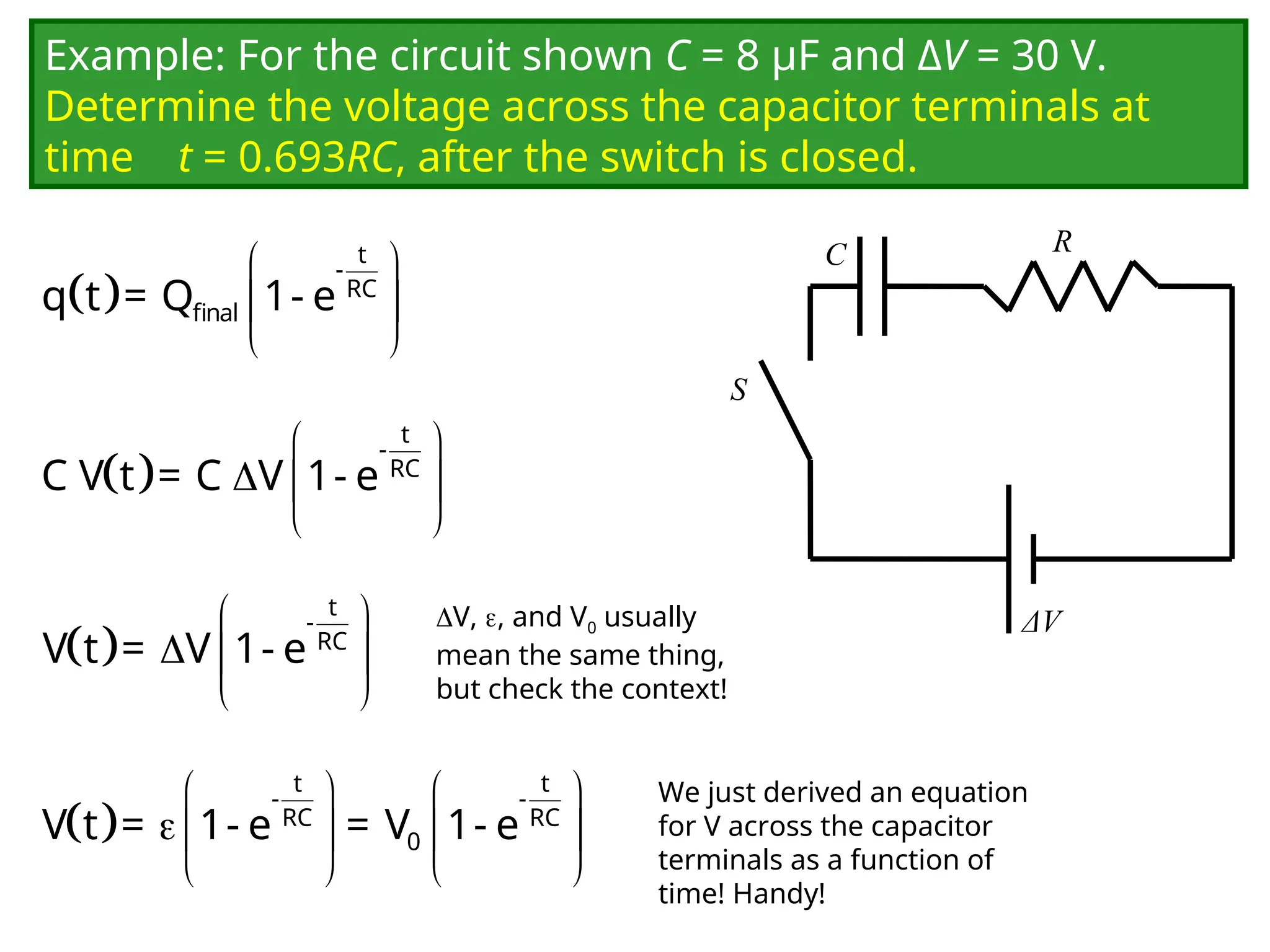
Example: For thecircuit shown C = 8 μF and ΔV = 30 V.
Determine the voltage across the capacitor terminals at
time t = 0.693RC, after the switch is closed.
C
ΔV
R
S
t
-
RC
final
q t = Q 1- e
We just derived an equation
for V across the capacitor
terminals as a function of
time! Handy!
t
-
RC
C V t = C V 1- e
t
-
RC
V t = V 1- e
t t
- -
RC RC
0
V t = 1- e = V 1- e
V, , and V0 usually
mean the same thing,
but check the context!
44.
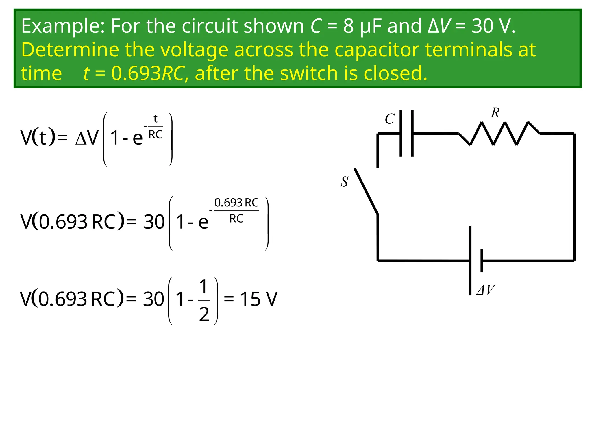
Example: For thecircuit shown C = 8 μF and ΔV = 30 V.
Determine the voltage across the capacitor terminals at
time t = 0.693RC, after the switch is closed.
C
ΔV
R
S
t
-
RC
V t = V 1- e
0.693RC
-
RC
V 0.693RC = 30 1- e
1
V 0.693RC = 30 1- = 15 V
2
45.
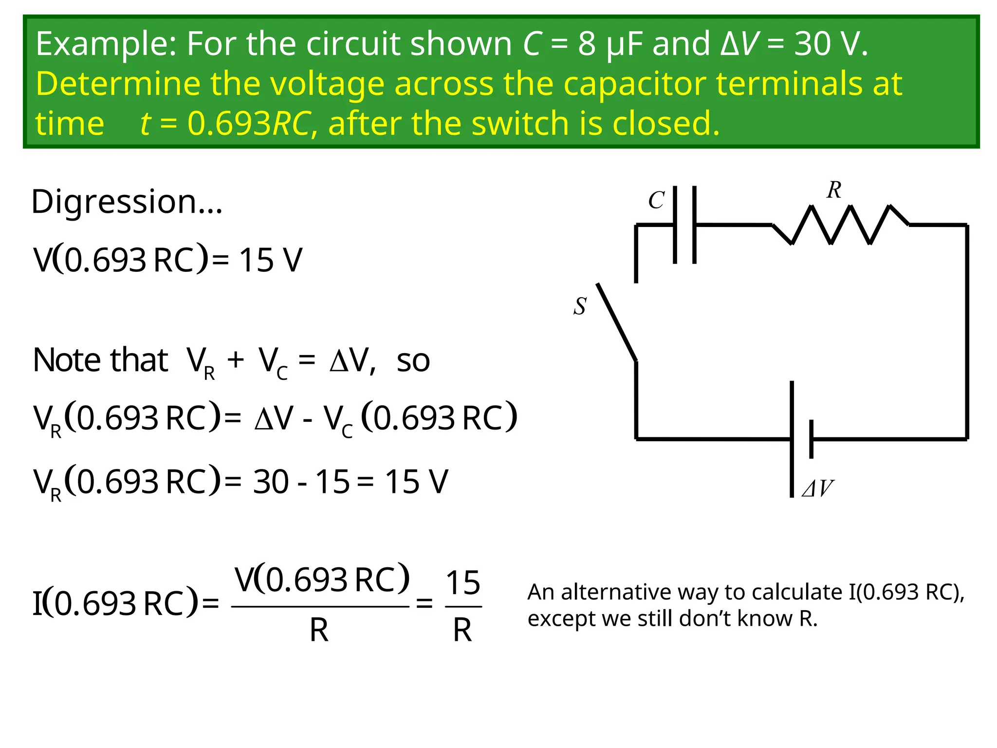
Example: For thecircuit shown C = 8 μF and ΔV = 30 V.
Determine the voltage across the capacitor terminals at
time t = 0.693RC, after the switch is closed.
C
ΔV
R
S
V 0.693RC = 15 V
R C
Note that V + V = V, so
R C
V 0.693RC = V - V 0.693RC
R
V 0.693RC = 30 - 15= 15 V
V 0.693RC 15
I 0.693RC = =
R R
An alternative way to calculate I(0.693 RC),
except we still don’t know R.
Digression…
46.
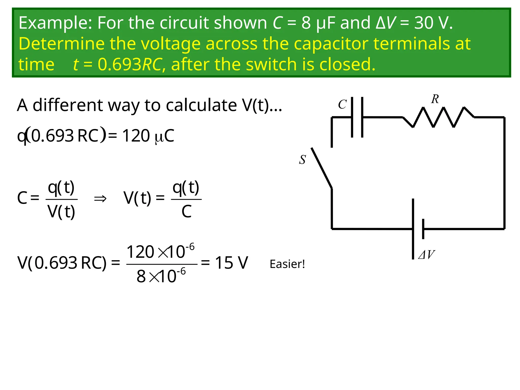
Example: For thecircuit shown C = 8 μF and ΔV = 30 V.
Determine the voltage across the capacitor terminals at
time t = 0.693RC, after the switch is closed.
C
ΔV
R
S
q 0.693RC = 120 C
q(t) q(t)
C= V(t) =
V(t) C
Easier!
A different way to calculate V(t)…
-6
-6
120 10
V(0.693RC) = = 15 V
8 10
47.
Demo
Charging and discharging
acapacitor.
Instead of doing a physical demo, if I have time I will do a virtual demo using
the applet linked on the next slide. The applet illustrates the same principles as
the physical demo.
48.
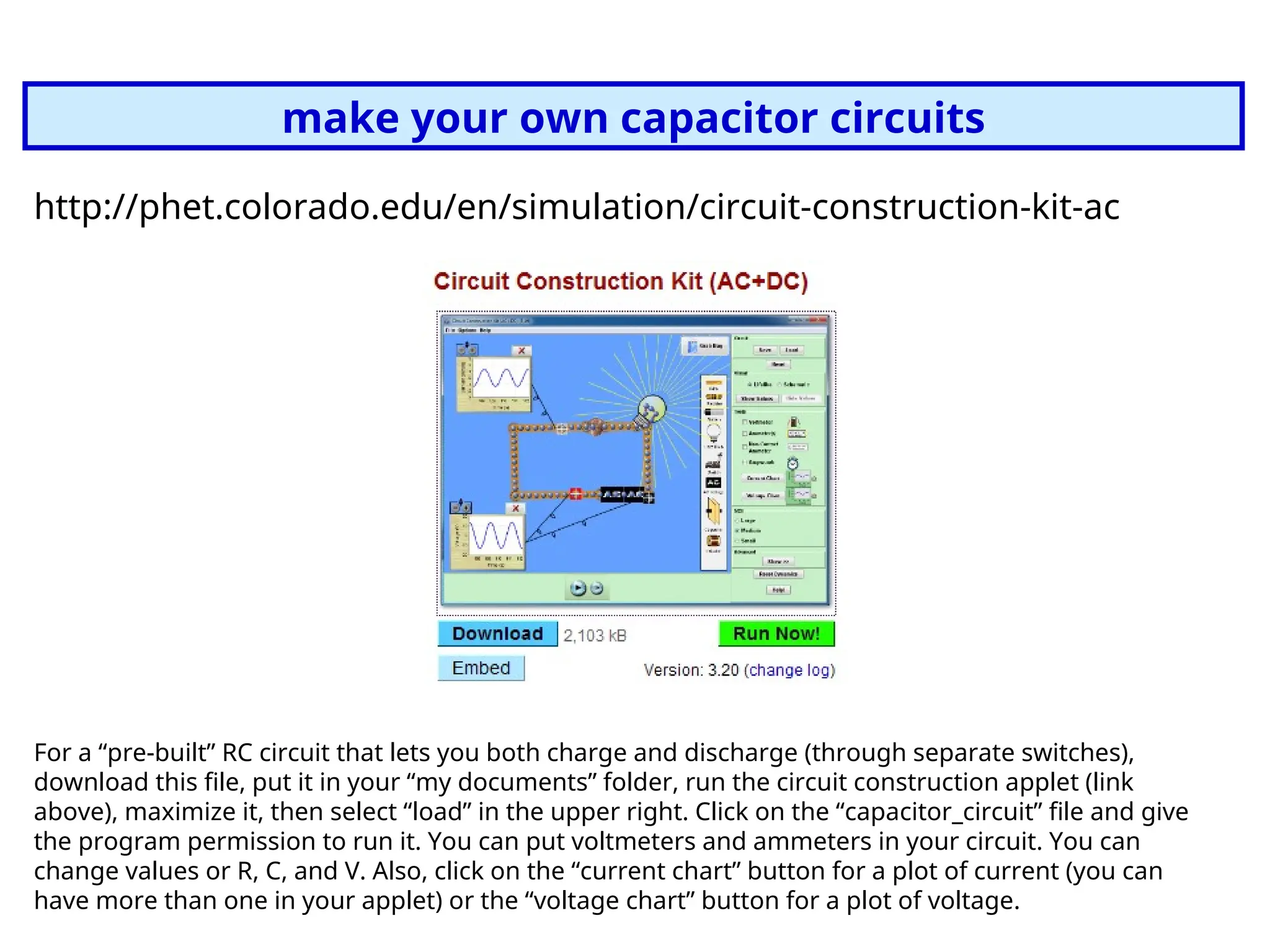
make your owncapacitor circuits
http://phet.colorado.edu/en/simulation/circuit-construction-kit-ac
For a “pre-built” RC circuit that lets you both charge and discharge (through separate switches),
download this file, put it in your “my documents” folder, run the circuit construction applet (link
above), maximize it, then select “load” in the upper right. Click on the “capacitor_circuit” file and give
the program permission to run it. You can put voltmeters and ammeters in your circuit. You can
change values or R, C, and V. Also, click on the “current chart” button for a plot of current (you can
have more than one in your applet) or the “voltage chart” button for a plot of voltage.
![Charging Discharging
Charge Q(t) Q(t) = Qfinal(1-e-t/
) Q(t) = Q0 e-t/
Capacitor voltage VC(t) VC(t) = (1-e-t/
) VC(t) = V0 e-t/
= (Q0/C) e-t/
Resistor voltage VR(t) VR(t) = -VC(t)
= e-t/
VR(t) = VC(t)=V0 e-t/
= (Q0/C) e-t/
Current I(t) I(t) = I0 e-t/
= (/R) e-t/
I(t) = I0 e-t/
= [Q0/(RC)] e-t/
Only the equations for the charge Q(t) are starting equations. You
must be able to derive the other quantities.
=RC](https://image.slidesharecdn.com/chap-3lecture13-251028125615-7cca8574/75/chap-3lecture13-pptIEC-61850-Standard-For-Substation-Automation-36-2048.jpg)