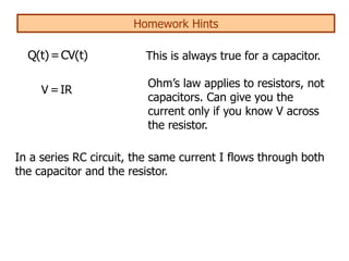
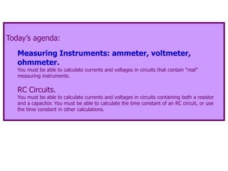
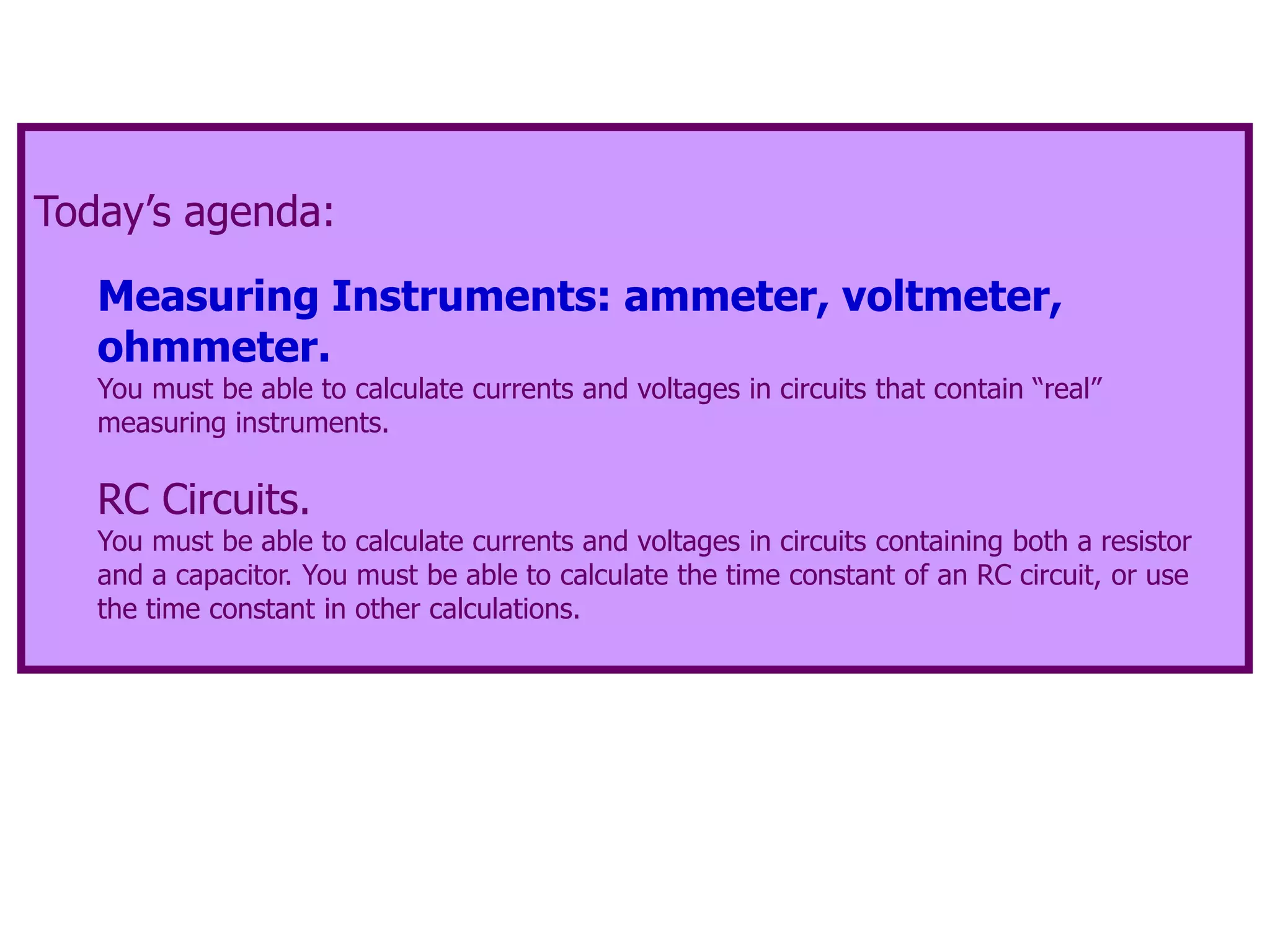
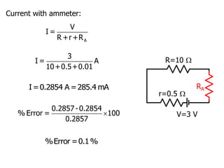
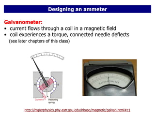
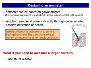
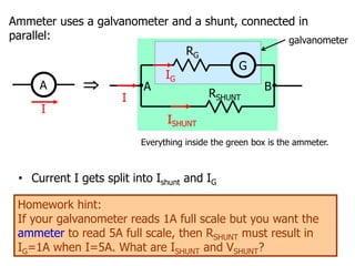
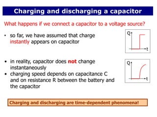
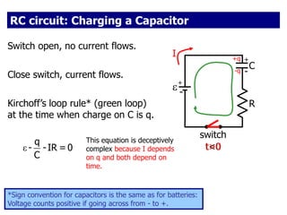
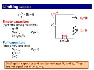
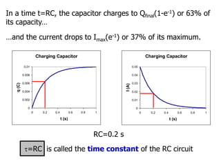
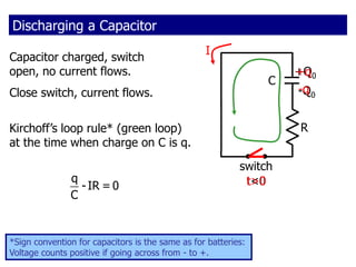
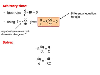
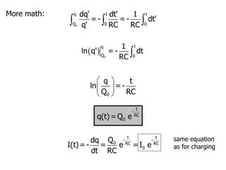
The document discusses measuring instruments, RC circuits, and charging/discharging capacitors. It begins with an agenda covering measuring instruments like ammeters, voltmeters, and ohmmeters. It then discusses calculating currents and voltages in RC circuits, and calculating the time constant of an RC circuit. The document provides details on how ammeters, voltmeters, and ohmmeters work, including the effects of their internal resistances on measurements. It also covers charging and discharging a capacitor in an RC circuit over time using differential equations and plots the capacitor voltage, charge, and current versus time.
![Charging Discharging
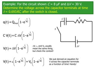
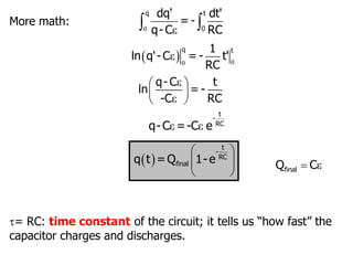
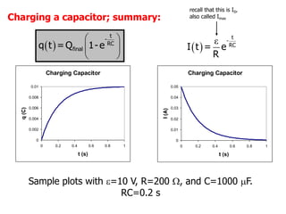
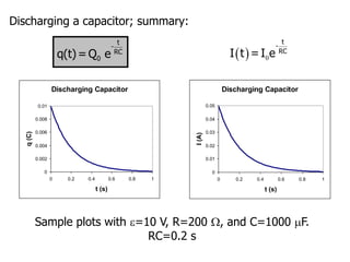
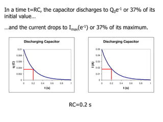
Charge Q(t) Q(t) = Qfinal(1-e-t/) Q(t) = Q0 e-t/
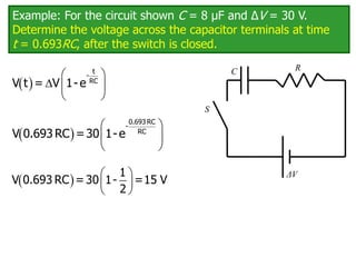
Capacitor voltage VC(t) VC(t) = (1-e-t/) VC(t) = V0 e-t/
= (Q0/C) e-t/
Resistor voltage VR(t) VR(t) = -VC(t)
= e-t/
VR(t) = VC(t)=V0 e-t/
= (Q0/C) e-t/
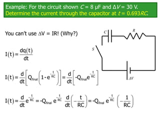
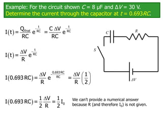
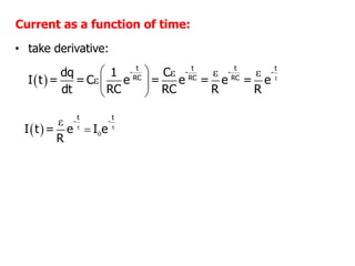
Current I(t) I(t) = I0 e-t/
= (/R) e-t/
I(t) = I0 e-t/
= [Q0/(RC)] e-t/
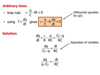
Only the equations for the charge Q(t) are starting equations. You must
be able to derive the other quantities.
=RC](https://image.slidesharecdn.com/emmaterialeee-230625164042-4157025e/85/EM-material-eee-ppt-36-320.jpg)