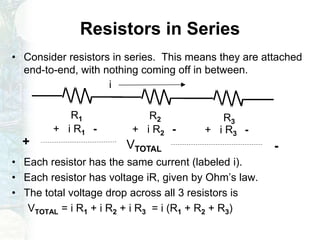
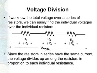
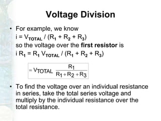
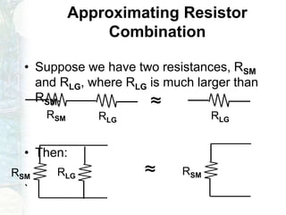
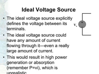
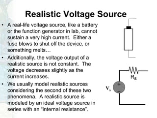
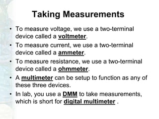
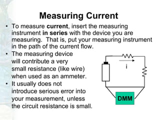
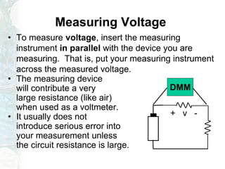
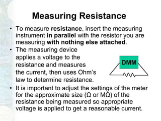
Linear Circuit Analysis
Dr.Muhammad Talha Gul
1
Introduction to Linear Circuit
Analysis
Introduction Circuits for Electrical and Computer Engineering:
By
James W. Nilsson, Susan A. Riedel
Fundamentals of Electric Circuits
By
Charles K Alexander, Mathew N O Sadiku
Resource Person: Dr. Muhammad Talha Gul
Assistant Professor, FET, Superior University, Lahore
2
Books
• Text Book
– Electric Circuits, by Nilsson & Riedel 2009
• Reference Books
– Fundamentals of Electric Circuits, 3rd Ed., By
Alexander and Sadiku, McGraw-Hill
– Basic Engineering Circuit Analysis, 8t h Ed., By J.
David Irwin, John Wiley & Sons
3
Class Information
Meeting time: All week after class.
Email ID: talha.gul@superior.edu.pk
• Everything will be discuss there, including:
– Syllabus.
– News.
– Projects, etc
4
Course Objective
• Cover topics on Linear Circuit Analysis.
• Emphasis on Circuits Variables.
• Emphasis on Circuits Simplification techniques.
5
Resistors in Series
• Consider resistors in series. This means they are attached
end-to-end, with nothing coming off in between.
• Each resistor has the same current (labeled i).
• Each resistor has voltage iR, given by Ohm’s law.
• The total voltage drop across all 3 resistors is
VTOTAL = i R1 + i R2 + i R3 = i (R1 + R2 + R3)
i
R1 R2 R3
+ i R1 - + i R2 - + i R3 -
+ -VTOTAL
Voltage Division
• If we know the total voltage over a series of
resistors, we can easily find the individual voltages
over the individual resistors.
• Since the resistors in series have the same current,
the voltage divides up among the resistors in
proportion to each individual resistance.
R1 R2 R3
+ i R1 - + i R2 - + i R3 -
+ -VTOTAL
Voltage Division
• For example, we know
i = VTOTAL / (R1 + R2 + R3)
so the voltage over the first resistor is
i R1 = R1 VTOTAL / (R1 + R2 + R3)
• To find the voltage over an individual resistance
in series, take the total series voltage and
multiply by the individual resistance over the
total resistance.
3R2R1R
1R
TOTALV


Elements in Parallel
• KVL tells us that any set of elements which are directly
connected by wire at both ends carry the same voltage.
• We say these elements are in parallel.
KVL clockwise,
start at top:
Vb – Va = 0
Va = Vb
Elements in Parallel--Examples
Which of these resistors are in parallel?
R1
R2
R3
R4 R5
R6
R7
R8
None
R4 and R5
R7 and R8
Resistors in Parallel
• Resistors in parallel carry the same voltage. All of
the resistors below have voltage VR .
• The current flowing through each resistor could
definitely be different. Even though they have the
same voltage, the resistances could be different.
R1 R2 R3
+
VR
_i1 i2 i3
i1 = VR / R1
i2 = VR / R2
i3 = VR / R3
Current Division
• If we know the current flowing into two parallel resistors, we
can find out how the current will divide up in one step.
• The value of the current through R1 is
i1 = iTOTAL R2 / (R1 + R2)
• The value of the current through R2 is
i2 = iTOTAL R1 / (R1 + R2)
• Note that this differs slightly
from the voltage division
formula for series resistors.
R1 R2
i1 i2
iTOTAL
Current Division—Other Cases
• If more than two resistors are in parallel, one can:
– Find the voltage over the resistors, VR, by combining the
resistors in parallel and computing VR = iTOTAL REQ.
Then, use Ohm’s law to find i1 = VR / R1, etc.
– Or, leave the resistor of interest alone, and combine other
resistors in parallel. Use the equation for two resistors.
R1 R2 R3
+
VR
_ i1 i2 i3
REQ
+
VR
_
iTOTAL iTOTAL
Example
• For the above circuit, what is i1?
• Suppose i1 was measured using an ammeter
with internal resistance 1 Ω. What would the
meter read?
9 Ω 27 Ω
i1 i2 i3
54 Ω3 A
Example
• By current division, i1 = -3 A (18 Ω)/(9 Ω+18 Ω) = -2 A
• When the ammeter is placed in series with the 9 Ω,
• Now, i1 = -3 A (18 Ω)/(10 Ω+18 Ω) = -1.93 A
9 Ω 27 Ω
i1 i2 i3
54 Ω3 A 9 Ω 18 Ω
i1
3 A
9 Ω 27 Ω
i1 i2 i3
54 Ω3 A 10 Ω 18 Ω
i1
3 A
1 Ω
Issues with Series and Parallel
Combination
• Resistors in series and resistors in parallel, when
considered as a group, have the same I-V relationship
as a single resistor.
• If the group of resistors is part of a larger circuit, the rest
of the circuit cannot tell whether there are separate
resistors in series (or parallel) or just one equivalent
resistor. All voltages and currents outside the group are
the same whether resistors are separate or combined.
• Thus, when you want to find currents and voltages
outside the group of resistors, it is good to use the
simpler equivalent resistor.
• Once you simplify the resistors down to one, you
(temporarily) lose the current or voltage information for
the individual resistors involved.
Issues with Series and Parallel
Combination
• For resistors in series:
– The individual resistors have the same
current as the single equivalent resistor.
– The voltage across the single equivalent
resistor is the sum of the voltages across the
individual resistors.
– Individual voltages and currents can be
recovered using Ohm’s law or voltage
division.
i
R1 R2 R3
v -+
i
+ v -
REQ
Approximating Resistor
Combination
• Suppose we have two resistances, RSM
and RLG, where RLG is much larger than
RSM.
• Then:
`
RSM RLG
≈
RLG
RSM RLG ≈ RSM
Ideal Voltage Source
• The ideal voltage source explicitly
defines the voltage between its
terminals.
• The ideal voltage source could
have any amount of current
flowing through it—even a really
large amount of current.
• This would result in high power
generation or absorption
(remember P=vi), which is


Vs
Realistic Voltage Source
• A real-life voltage source, like a battery
or the function generator in lab, cannot
sustain a very high current. Either a
fuse blows to shut off the device, or
something melts…
• Additionally, the voltage output of a
realistic source is not constant. The
voltage decreases slightly as the
current increases.
• We usually model realistic sources
considering the second of these two
phenomena. A realistic source is
modeled by an ideal voltage source in
series with an “internal resistance”.


Vs
RS
Realistic Current Source
• Constant-current sources are much less
common than voltage sources.
• There are a variety of circuits that can
produces constant currents, and these
circuits are usually composed of transistors.
• Analogous to realistic voltage sources, the
current output of the realistic constant
currents source does depend on the
voltage. We may investigate this
dependence further when we study
transistors.
Taking Measurements
• To measure voltage, we use a two-terminal
device called a voltmeter.
• To measure current, we use a two-terminal
device called a ammeter.
• To measure resistance, we use a two-terminal
device called a ohmmeter.
• A multimeter can be setup to function as any of
these three devices.
• In lab, you use a DMM to take measurements,
which is short for digital multimeter .
Measuring Current
• To measure current, insert the measuring
instrument in series with the device you are
measuring. That is, put your measuring instrument
in the path of the current flow.
• The measuring device
will contribute a very
small resistance (like wire)
when used as an ammeter.
• It usually does not
introduce serious error into
your measurement, unless
the circuit resistance is small.
i
DMM
Measuring Voltage
• To measure voltage, insert the measuring
instrument in parallel with the device you are
measuring. That is, put your measuring instrument
across the measured voltage.
• The measuring device
will contribute a very
large resistance (like air)
when used as a voltmeter.
• It usually does not
introduce serious error into
your measurement unless
the circuit resistance is large.
+ v -
DMM
Measuring Resistance
• To measure resistance, insert the measuring
instrument in parallel with the resistor you are
measuring with nothing else attached.
• The measuring device
applies a voltage to the
resistance and measures
the current, then uses Ohm’s
law to determine resistance.
• It is important to adjust the settings of the meter
for the approximate size (Ω or MΩ) of the
resistance being measured so appropriate
voltage is applied to get a reasonable current.
DMM
26
Questions?

Linear circuit analysis 3

  • 1.
  • 2.
    Introduction to LinearCircuit Analysis Introduction Circuits for Electrical and Computer Engineering: By James W. Nilsson, Susan A. Riedel Fundamentals of Electric Circuits By Charles K Alexander, Mathew N O Sadiku Resource Person: Dr. Muhammad Talha Gul Assistant Professor, FET, Superior University, Lahore 2
  • 3.
    Books • Text Book –Electric Circuits, by Nilsson & Riedel 2009 • Reference Books – Fundamentals of Electric Circuits, 3rd Ed., By Alexander and Sadiku, McGraw-Hill – Basic Engineering Circuit Analysis, 8t h Ed., By J. David Irwin, John Wiley & Sons 3
  • 4.
    Class Information Meeting time:All week after class. Email ID: talha.gul@superior.edu.pk • Everything will be discuss there, including: – Syllabus. – News. – Projects, etc 4
  • 5.
    Course Objective • Covertopics on Linear Circuit Analysis. • Emphasis on Circuits Variables. • Emphasis on Circuits Simplification techniques. 5
  • 6.
    Resistors in Series •Consider resistors in series. This means they are attached end-to-end, with nothing coming off in between. • Each resistor has the same current (labeled i). • Each resistor has voltage iR, given by Ohm’s law. • The total voltage drop across all 3 resistors is VTOTAL = i R1 + i R2 + i R3 = i (R1 + R2 + R3) i R1 R2 R3 + i R1 - + i R2 - + i R3 - + -VTOTAL
  • 7.
    Voltage Division • Ifwe know the total voltage over a series of resistors, we can easily find the individual voltages over the individual resistors. • Since the resistors in series have the same current, the voltage divides up among the resistors in proportion to each individual resistance. R1 R2 R3 + i R1 - + i R2 - + i R3 - + -VTOTAL
  • 8.
    Voltage Division • Forexample, we know i = VTOTAL / (R1 + R2 + R3) so the voltage over the first resistor is i R1 = R1 VTOTAL / (R1 + R2 + R3) • To find the voltage over an individual resistance in series, take the total series voltage and multiply by the individual resistance over the total resistance. 3R2R1R 1R TOTALV  
  • 9.
    Elements in Parallel •KVL tells us that any set of elements which are directly connected by wire at both ends carry the same voltage. • We say these elements are in parallel. KVL clockwise, start at top: Vb – Va = 0 Va = Vb
  • 10.
    Elements in Parallel--Examples Whichof these resistors are in parallel? R1 R2 R3 R4 R5 R6 R7 R8 None R4 and R5 R7 and R8
  • 11.
    Resistors in Parallel •Resistors in parallel carry the same voltage. All of the resistors below have voltage VR . • The current flowing through each resistor could definitely be different. Even though they have the same voltage, the resistances could be different. R1 R2 R3 + VR _i1 i2 i3 i1 = VR / R1 i2 = VR / R2 i3 = VR / R3
  • 12.
    Current Division • Ifwe know the current flowing into two parallel resistors, we can find out how the current will divide up in one step. • The value of the current through R1 is i1 = iTOTAL R2 / (R1 + R2) • The value of the current through R2 is i2 = iTOTAL R1 / (R1 + R2) • Note that this differs slightly from the voltage division formula for series resistors. R1 R2 i1 i2 iTOTAL
  • 13.
    Current Division—Other Cases •If more than two resistors are in parallel, one can: – Find the voltage over the resistors, VR, by combining the resistors in parallel and computing VR = iTOTAL REQ. Then, use Ohm’s law to find i1 = VR / R1, etc. – Or, leave the resistor of interest alone, and combine other resistors in parallel. Use the equation for two resistors. R1 R2 R3 + VR _ i1 i2 i3 REQ + VR _ iTOTAL iTOTAL
  • 14.
    Example • For theabove circuit, what is i1? • Suppose i1 was measured using an ammeter with internal resistance 1 Ω. What would the meter read? 9 Ω 27 Ω i1 i2 i3 54 Ω3 A
  • 15.
    Example • By currentdivision, i1 = -3 A (18 Ω)/(9 Ω+18 Ω) = -2 A • When the ammeter is placed in series with the 9 Ω, • Now, i1 = -3 A (18 Ω)/(10 Ω+18 Ω) = -1.93 A 9 Ω 27 Ω i1 i2 i3 54 Ω3 A 9 Ω 18 Ω i1 3 A 9 Ω 27 Ω i1 i2 i3 54 Ω3 A 10 Ω 18 Ω i1 3 A 1 Ω
  • 16.
    Issues with Seriesand Parallel Combination • Resistors in series and resistors in parallel, when considered as a group, have the same I-V relationship as a single resistor. • If the group of resistors is part of a larger circuit, the rest of the circuit cannot tell whether there are separate resistors in series (or parallel) or just one equivalent resistor. All voltages and currents outside the group are the same whether resistors are separate or combined. • Thus, when you want to find currents and voltages outside the group of resistors, it is good to use the simpler equivalent resistor. • Once you simplify the resistors down to one, you (temporarily) lose the current or voltage information for the individual resistors involved.
  • 17.
    Issues with Seriesand Parallel Combination • For resistors in series: – The individual resistors have the same current as the single equivalent resistor. – The voltage across the single equivalent resistor is the sum of the voltages across the individual resistors. – Individual voltages and currents can be recovered using Ohm’s law or voltage division. i R1 R2 R3 v -+ i + v - REQ
  • 18.
    Approximating Resistor Combination • Supposewe have two resistances, RSM and RLG, where RLG is much larger than RSM. • Then: ` RSM RLG ≈ RLG RSM RLG ≈ RSM
  • 19.
    Ideal Voltage Source •The ideal voltage source explicitly defines the voltage between its terminals. • The ideal voltage source could have any amount of current flowing through it—even a really large amount of current. • This would result in high power generation or absorption (remember P=vi), which is   Vs
  • 20.
    Realistic Voltage Source •A real-life voltage source, like a battery or the function generator in lab, cannot sustain a very high current. Either a fuse blows to shut off the device, or something melts… • Additionally, the voltage output of a realistic source is not constant. The voltage decreases slightly as the current increases. • We usually model realistic sources considering the second of these two phenomena. A realistic source is modeled by an ideal voltage source in series with an “internal resistance”.   Vs RS
  • 21.
    Realistic Current Source •Constant-current sources are much less common than voltage sources. • There are a variety of circuits that can produces constant currents, and these circuits are usually composed of transistors. • Analogous to realistic voltage sources, the current output of the realistic constant currents source does depend on the voltage. We may investigate this dependence further when we study transistors.
  • 22.
    Taking Measurements • Tomeasure voltage, we use a two-terminal device called a voltmeter. • To measure current, we use a two-terminal device called a ammeter. • To measure resistance, we use a two-terminal device called a ohmmeter. • A multimeter can be setup to function as any of these three devices. • In lab, you use a DMM to take measurements, which is short for digital multimeter .
  • 23.
    Measuring Current • Tomeasure current, insert the measuring instrument in series with the device you are measuring. That is, put your measuring instrument in the path of the current flow. • The measuring device will contribute a very small resistance (like wire) when used as an ammeter. • It usually does not introduce serious error into your measurement, unless the circuit resistance is small. i DMM
  • 24.
    Measuring Voltage • Tomeasure voltage, insert the measuring instrument in parallel with the device you are measuring. That is, put your measuring instrument across the measured voltage. • The measuring device will contribute a very large resistance (like air) when used as a voltmeter. • It usually does not introduce serious error into your measurement unless the circuit resistance is large. + v - DMM
  • 25.
    Measuring Resistance • Tomeasure resistance, insert the measuring instrument in parallel with the resistor you are measuring with nothing else attached. • The measuring device applies a voltage to the resistance and measures the current, then uses Ohm’s law to determine resistance. • It is important to adjust the settings of the meter for the approximate size (Ω or MΩ) of the resistance being measured so appropriate voltage is applied to get a reasonable current. DMM
  • 26.