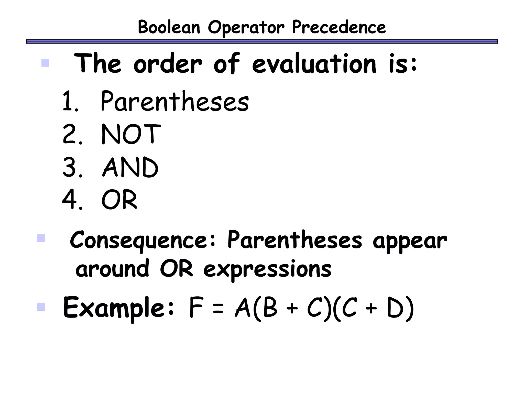
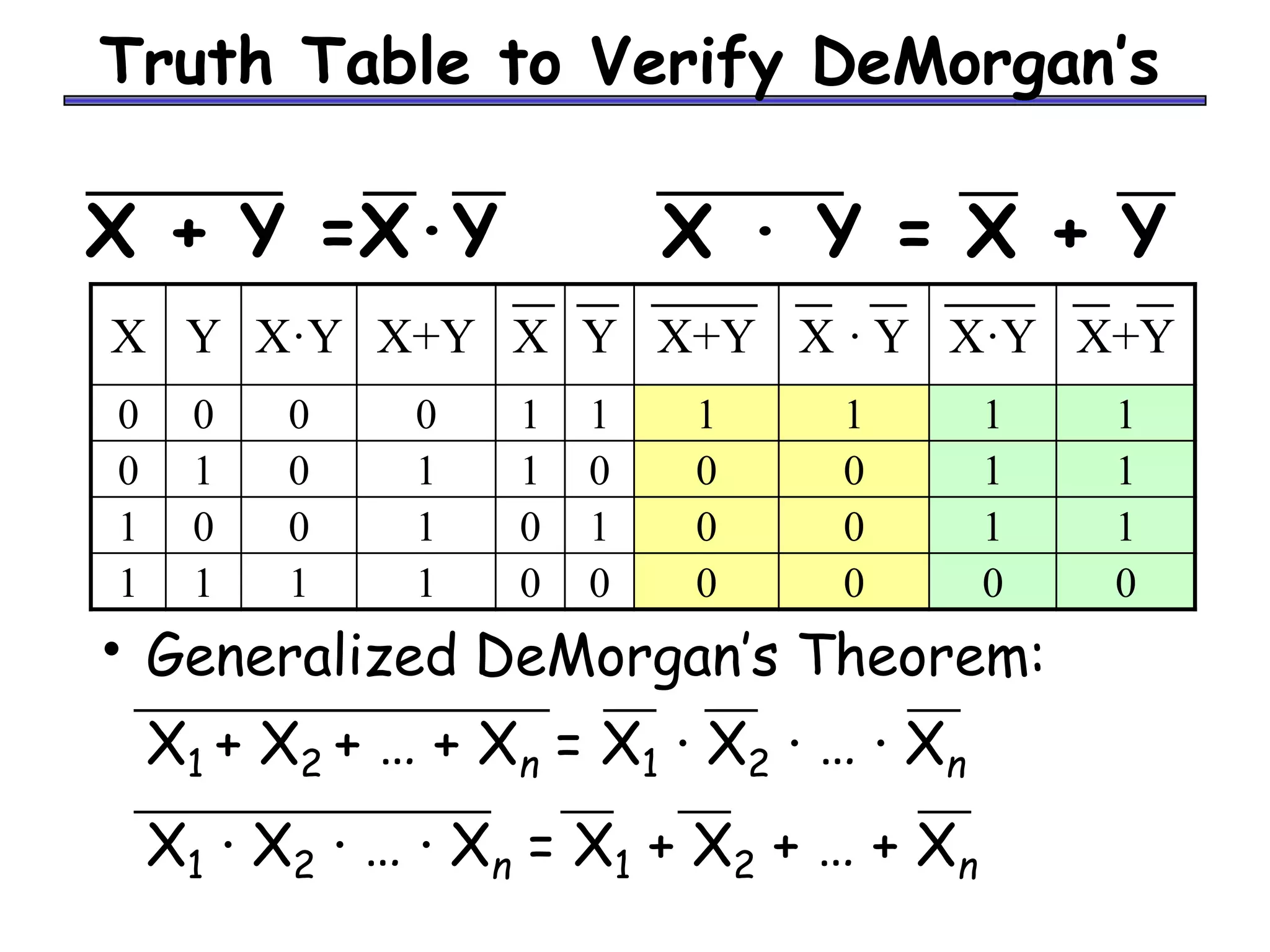
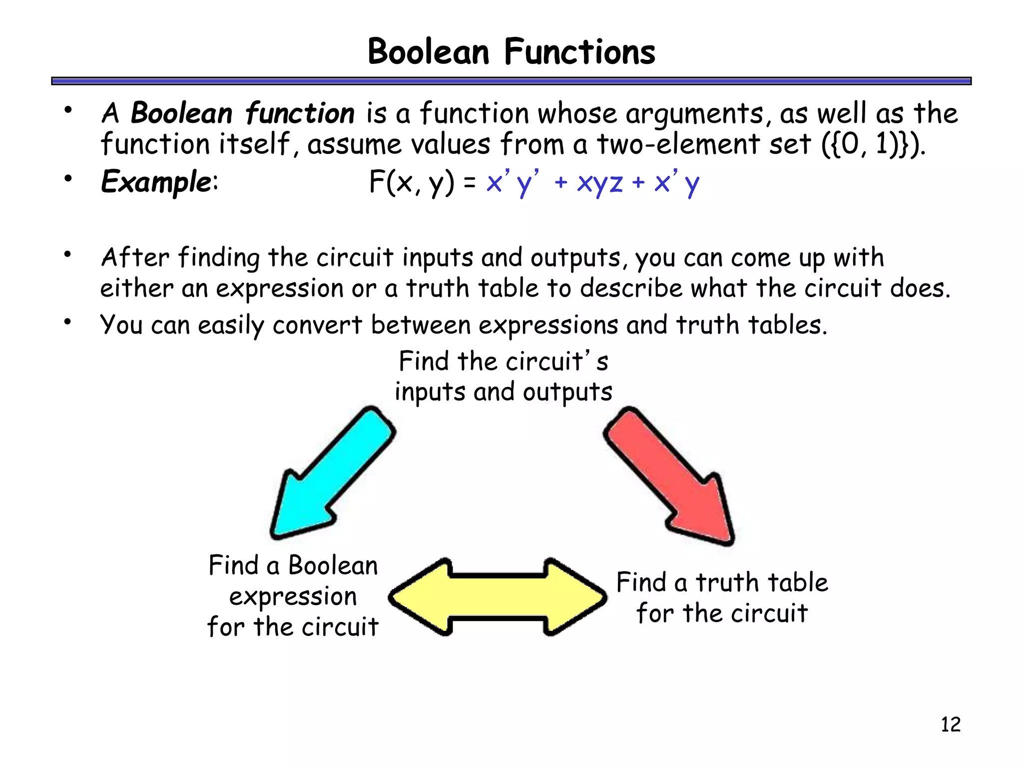
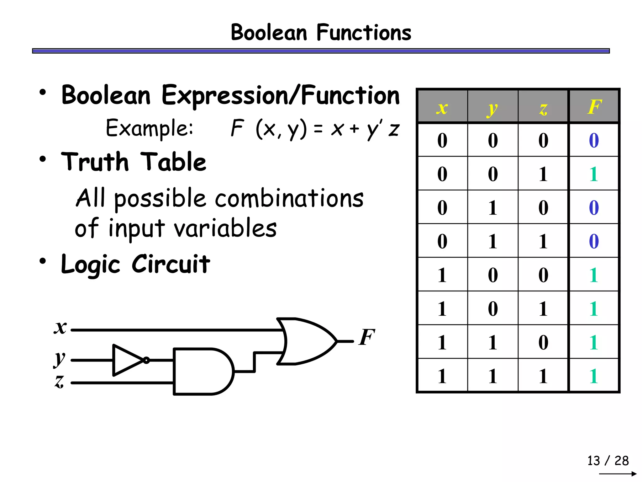
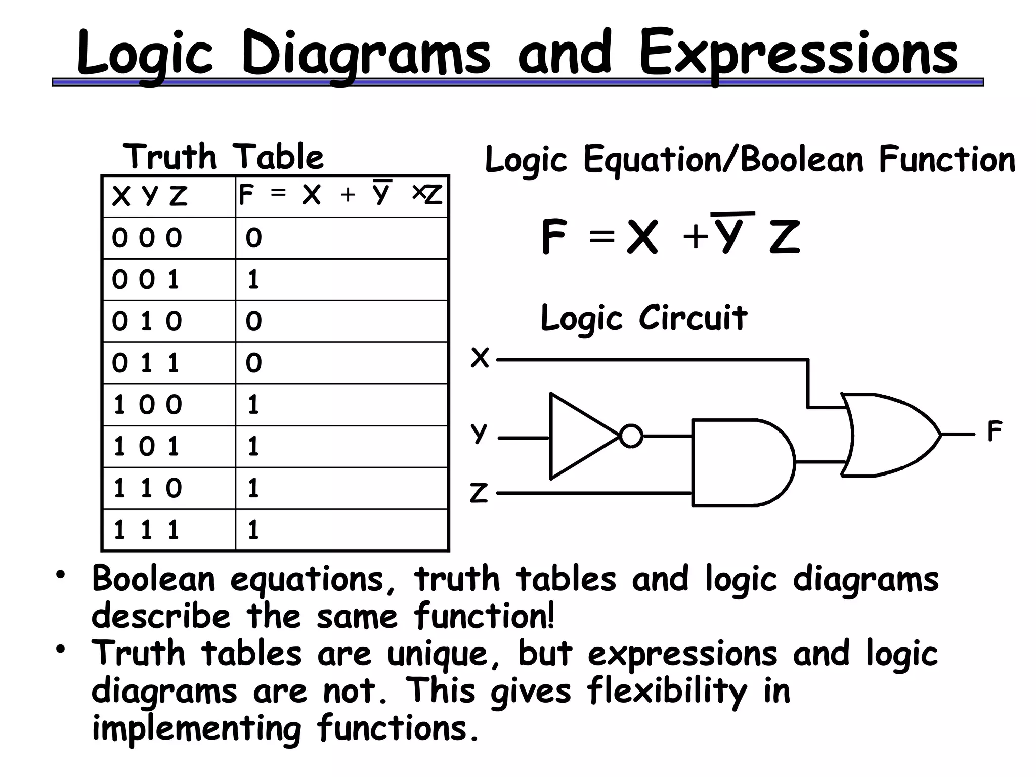
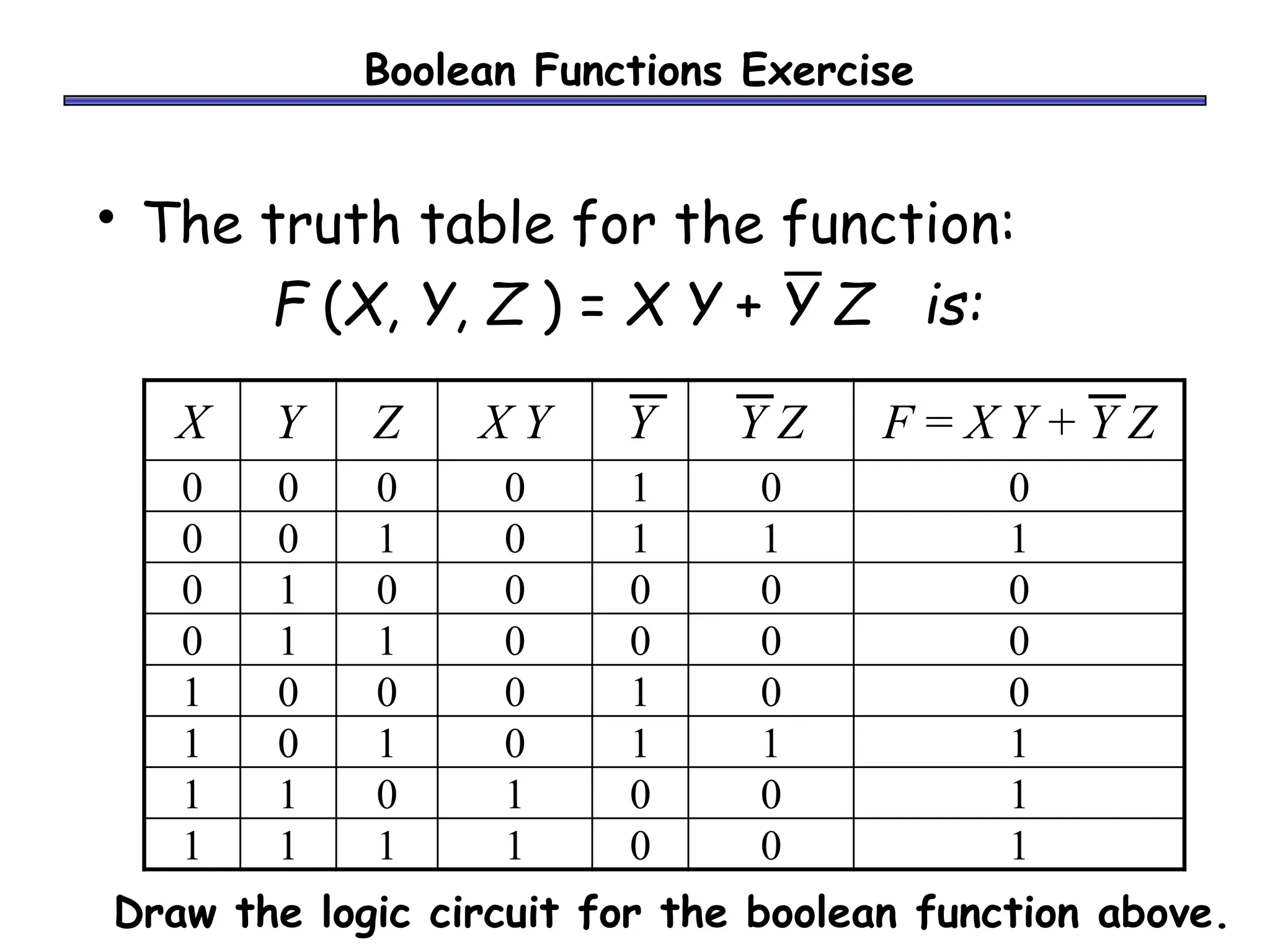
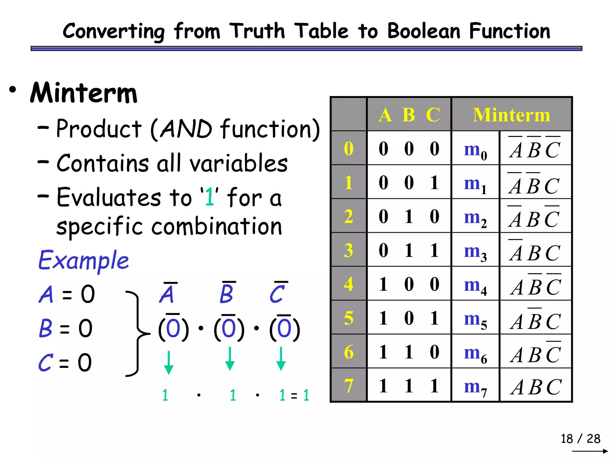
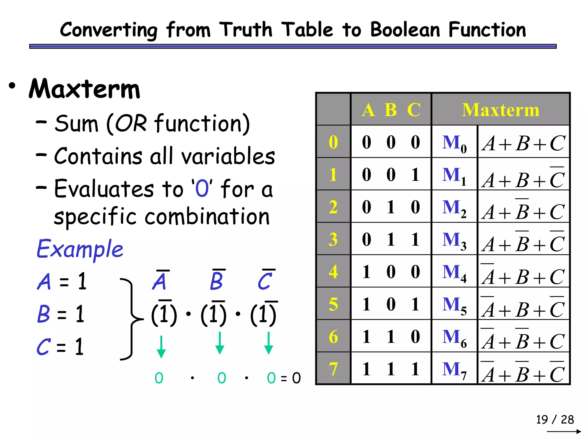
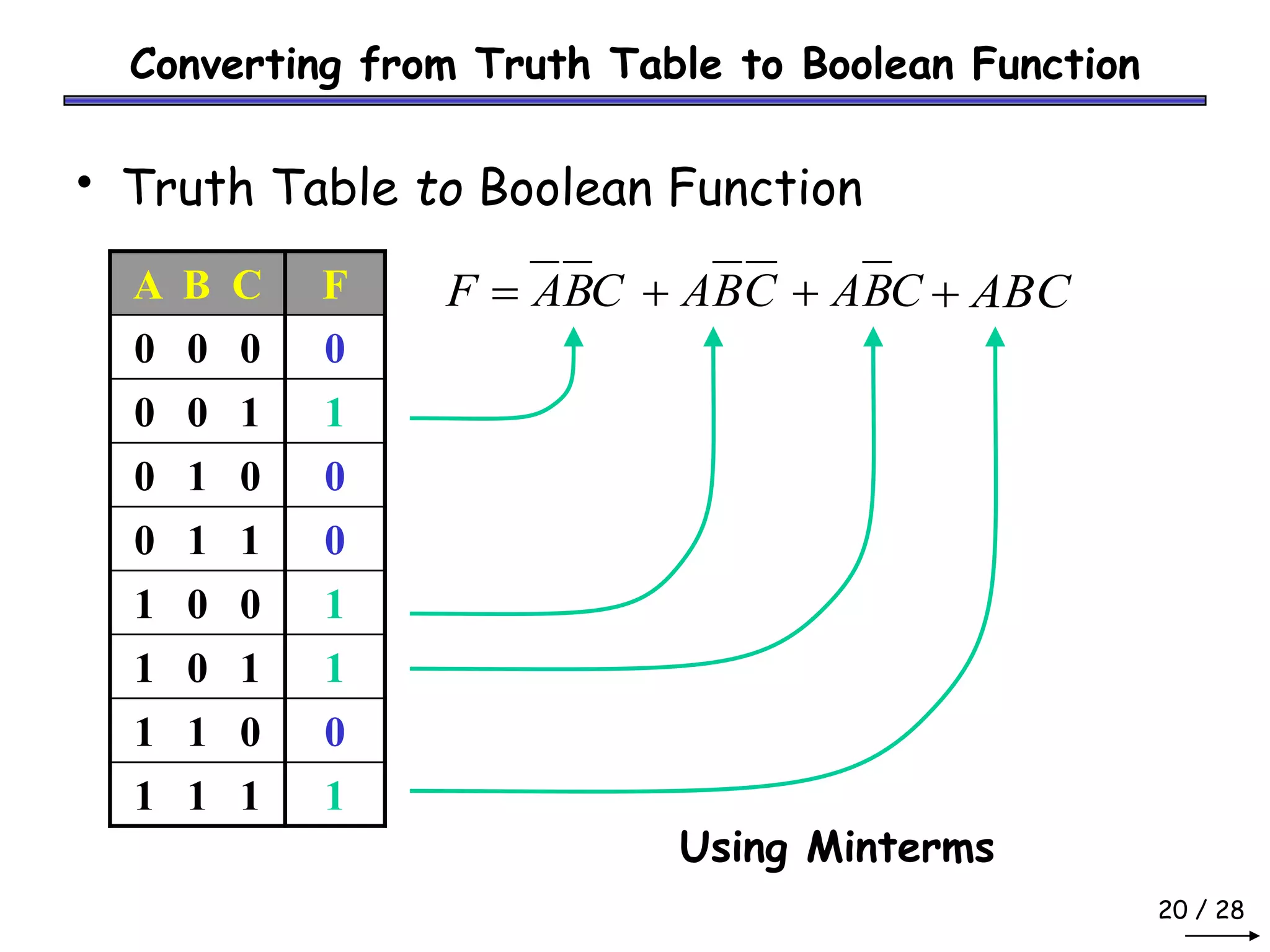
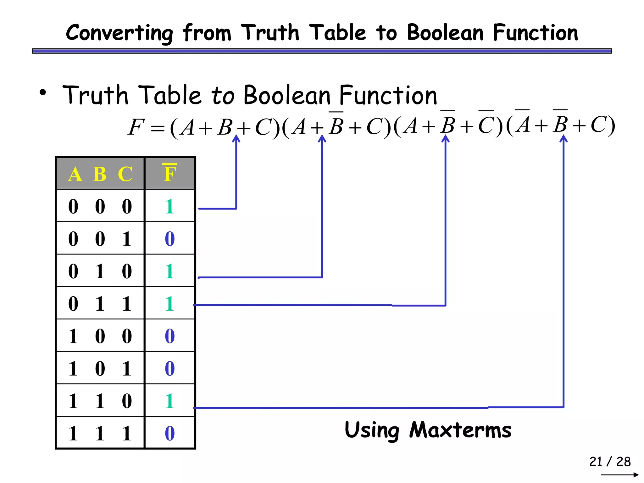
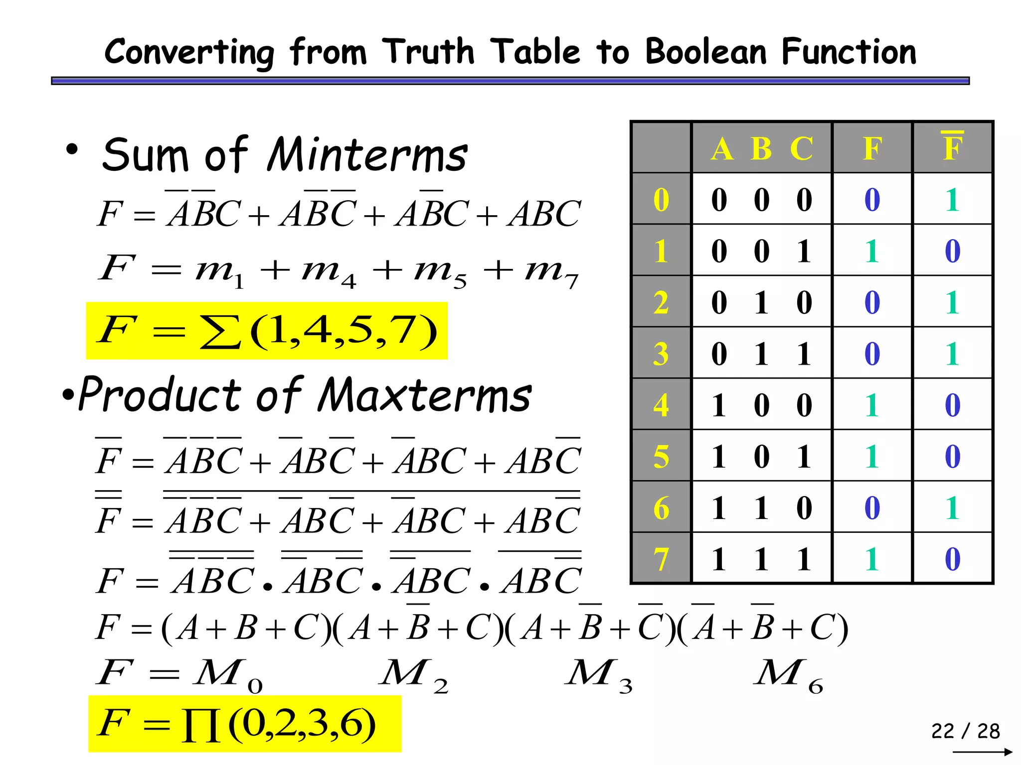
Boolean Algebra
2
Boolean Algebra Summary
• We can interpret high or low voltage as representing true or
false.
• A variable whose value can be either 1 or 0 is called a Boolean
variable.
• AND, OR, and NOT are the basic Boolean operations.
• We can express Boolean functions with either an expression or a
truth table.
• Every Boolean expression can be converted to a circuit.
• Now, we’ll look at how Boolean algebra can help simplify
expressions, which in turn will lead to simpler circuits.
3
Boolean Algebra Summary
• Recall that the two binary values have different names:
– True/False
– On/Off
– Yes/No
– 1/0
• We use 1 and 0 to denote the two values.
• The three basic logical operations are:
– AND
– OR
– NOT
• AND is denoted by a dot (·).
• OR is denoted by a plus (+).
• NOT is denoted by an overbar ( ¯ ), a single quote mark (')
after, or (~) before the variable
4
Boolean Algebra Summary
• Examples:
– is read “Y is equal to A AND B.”
– is read “z is equal to x OR y.”
– is read “X is equal to NOT A.”
Tabular listing of the values of a function for all possible
combinations of values on its arguments
Example: Truth tables for the basic logic operations:
1
1
1
0
0
1
0
1
0
0
0
0
Z = X·Y
Y
X
AND OR
X Y Z = X+Y
0 0 0
0 1 1
1 0 1
1 1 1
0
1
1
0
X
NOT
X
Z=
Boolean Operator Precedence
 The order of evaluation is:
1. Parentheses
2. NOT
3. AND
4. OR
 Consequence: Parentheses appear
around OR expressions
 Example: F = A(B + C)(C + D)
6 / 28
Boolean Algebra Postulates
• Commutative Law
x • y = y • x x + y = y + x
• Identity Element
x • 1 = x x + 0 = x
x’1 = x’ x’+ 0 = x’
• Complement
x • x’ = 0 x + x’ = 1
7 / 28
Boolean Algebra Theorems
Theorem 1
– x • x = x x + x = x
• Theorem 2
– x • 0 = 0 x + 1 = 1
• Theorem 3: Involution
– ( x’ )’ = x ( x ) = x
8 / 28
Boolean Algebra Theorems
• Theorem 4:
– Associative: ( x • y ) • z = x • ( y • z )
( x + y ) + z = x + ( y + z )
– Distributive :
x • ( y + z ) = ( x • y ) + ( x • z )
x + ( y • z ) = ( x + y ) • ( x + z )
• Theorem 5: DeMorgan
– ( x • y )’ = x’ + y’ ( x + y )’ = x’ • y’
– x • y ) = x + y ( x + y ) = x • y
• Theorem 6: Absorption
– x • ( x + y ) = x x + ( x • y ) = x
Truth Table to Verify DeMorgan’s
X Y X·Y X+Y X Y X+Y X · Y X·Y X+Y
0 0 0 0 1 1 1 1 1 1
0 1 0 1 1 0 0 0 1 1
1 0 0 1 0 1 0 0 1 1
1 1 1 1 0 0 0 0 0 0
X + Y =X·Y X · Y = X + Y
• Generalized DeMorgan’s Theorem:
X1 + X2 + … + Xn = X1 · X2 · … · Xn
X1 · X2 · … · Xn = X1 + X2 + … + Xn
Logic Gates
• In the earliest computers, switches were
opened and closed by magnetic fields
produced by energizing coils in relays. The
switches in turn opened and closed the
current paths.
• Later, vacuum tubes that open and close
current paths electronically replaced relays.
• Today, transistors are used as electronic
switches that open and close current paths.
Logic Gate Symbols
• Logic gates have special symbols:
OR gate
X
Y
Z = X + Y
X
Y
Z = X ·Y
AND gate
X Z = X
NOT gate or
inverter
12
Boolean Functions
• A Boolean function is a function whose arguments, as well as the
function itself, assume values from a two-element set ({0, 1)}).
• Example: F(x, y) = x’y’ + xyz + x’y
• After finding the circuit inputs and outputs, you can come up with
either an expression or a truth table to describe what the circuit does.
• You can easily convert between expressions and truth tables.
Find the circuit’s
inputs and outputs
Find a Boolean
expression
for the circuit
Find a truth table
for the circuit
13 / 28
Boolean Functions
• Boolean Expression/Function
Example: F (x, y) = x + y’ z
• Truth Table
All possible combinations
of input variables
• Logic Circuit
x y z F
0 0 0 0
0 0 1 1
0 1 0 0
0 1 1 0
1 0 0 1
1 0 1 1
1 1 0 1
1 1 1 1
x
y
z
F
Logic Diagrams and Expressions
• Boolean equations, truth tables and logic diagrams
describe the same function!
• Truth tables are unique, but expressions and logic
diagrams are not. This gives flexibility in
implementing functions.
X
Y F
Z
Logic Circuit
Logic Equation/Boolean Function
Z
Y
X
F +
=
Truth Table
1
1 1 1
1
1 1 0
1
1 0 1
1
1 0 0
0
0 1 1
0
0 1 0
1
0 0 1
0
0 0 0
X Y Z Z
Y
X
F ×
+
=
Boolean Functions Exercise
• The truth table for the function:
F (X, Y, Z ) = X Y + Y Z is:
X Y Z X Y Y Y Z F = X Y + Y Z
0 0 0 0 1 0 0
0 0 1 0 1 1 1
0 1 0 0 0 0 0
0 1 1 0 0 0 0
1 0 0 0 1 0 0
1 0 1 0 1 1 1
1 1 0 1 0 0 1
1 1 1 1 0 0 1
Draw the logic circuit for the boolean function above.
Converting from Truth Table to Boolean Function
• In designing digital circuits, the designer often begins
with a truth table describing what the circuit should do.
• The design task is largely to determine what type of
circuit will perform the function described in the truth
table.
• While some people seem to have a natural ability to look
at a truth table and immediately envision the necessary
logic gate or relay logic circuitry for the task, there are
procedural techniques available for the rest of us.
• Here, Boolean algebra proves its utility in a most
dramatic way!
Converting from Truth Table to Boolean Function
• This problem will be solved by showing that any
Boolean function can be represented by a Boolean
sum of Boolean products of the variables and their
complements or the product of sums.
• There are two ways to convert from truth tables
to Boolean functions:
1. Using Sum of Products /Minterms
2. Using Product of Sums /Maxterms
18 / 28
Converting from Truth Table to Boolean Function
• Minterm
– Product (AND function)
– Contains all variables
– Evaluates to ‘1’ for a
specific combination
Example
A = 0 A B C
B = 0 (0) • (0) • (0)
C = 0
1 • 1 • 1 = 1
A B C Minterm
0 0 0 0 m0
1 0 0 1 m1
2 0 1 0 m2
3 0 1 1 m3
4 1 0 0 m4
5 1 0 1 m5
6 1 1 0 m6
7 1 1 1 m7
C
B
A
C
B
A
C
B
A
C
B
A
C
B
A
C
B
A
C
B
A
C
B
A
19 / 28
Converting from Truth Table to Boolean Function
• Maxterm
– Sum (OR function)
– Contains all variables
– Evaluates to ‘0’ for a
specific combination
Example
A = 1 A B C
B = 1 (1) • (1) • (1)
C = 1
0 • 0 • 0 = 0
A B C Maxterm
0 0 0 0 M0
1 0 0 1 M1
2 0 1 0 M2
3 0 1 1 M3
4 1 0 0 M4
5 1 0 1 M5
6 1 1 0 M6
7 1 1 1 M7
C
B
A +
+
C
B
A +
+
C
B
A +
+
C
B
A +
+
C
B
A +
+
C
B
A +
+
C
B
A +
+
C
B
A +
+
20 / 28
Converting from Truth Table to Boolean Function
• Truth Table to Boolean Function
A B C F
0 0 0 0
0 0 1 1
0 1 0 0
0 1 1 0
1 0 0 1
1 0 1 1
1 1 0 0
1 1 1 1
C
B
A
F = C
B
A
+ C
B
A
+ ABC
+
Using Minterms
21 / 28
Converting from Truth Table to Boolean Function
• Truth Table to Boolean Function
A B C F
0 0 0 1
0 0 1 0
0 1 0 1
0 1 1 1
1 0 0 0
1 0 1 0
1 1 0 1
1 1 1 0
)
( C
B
A
F +
+
= )
( C
B
A +
+
Using Maxterms
)
( C
B
A +
+ )
( C
B
A +
+
22 / 28
Converting from Truth Table to Boolean Function
• Sum of Minterms A B C F
0 0 0 0 0
1 0 0 1 1
2 0 1 0 0
3 0 1 1 0
4 1 0 0 1
5 1 0 1 1
6 1 1 0 0
7 1 1 1 1
ABC
C
B
A
C
B
A
C
B
A
F +
+
+
=
7
5
4
1 m
m
m
m
F +
+
+
=

= )
7
,
5
,
4
,
1
(
F
C
AB
BC
A
C
B
A
C
B
A
F +
+
+
=
C
AB
BC
A
C
B
A
C
B
A
F +
+
+
=
C
AB
BC
A
C
B
A
C
B
A
F 


=
)
)(
)(
)(
( C
B
A
C
B
A
C
B
A
C
B
A
F +
+
+
+
+
+
+
+
=
6
3
2
0 M
M
M
M
F =

= (0,2,3,6)
F
F
1
0
1
1
0
0
1
0
•Product of Maxterms

Lect 2 boolean algebra (4 5-21)

  • 1.
  • 2.
    2 Boolean Algebra Summary •We can interpret high or low voltage as representing true or false. • A variable whose value can be either 1 or 0 is called a Boolean variable. • AND, OR, and NOT are the basic Boolean operations. • We can express Boolean functions with either an expression or a truth table. • Every Boolean expression can be converted to a circuit. • Now, we’ll look at how Boolean algebra can help simplify expressions, which in turn will lead to simpler circuits.
  • 3.
    3 Boolean Algebra Summary •Recall that the two binary values have different names: – True/False – On/Off – Yes/No – 1/0 • We use 1 and 0 to denote the two values. • The three basic logical operations are: – AND – OR – NOT • AND is denoted by a dot (·). • OR is denoted by a plus (+). • NOT is denoted by an overbar ( ¯ ), a single quote mark (') after, or (~) before the variable
  • 4.
    4 Boolean Algebra Summary •Examples: – is read “Y is equal to A AND B.” – is read “z is equal to x OR y.” – is read “X is equal to NOT A.” Tabular listing of the values of a function for all possible combinations of values on its arguments Example: Truth tables for the basic logic operations: 1 1 1 0 0 1 0 1 0 0 0 0 Z = X·Y Y X AND OR X Y Z = X+Y 0 0 0 0 1 1 1 0 1 1 1 1 0 1 1 0 X NOT X Z=
  • 5.
    Boolean Operator Precedence The order of evaluation is: 1. Parentheses 2. NOT 3. AND 4. OR  Consequence: Parentheses appear around OR expressions  Example: F = A(B + C)(C + D)
  • 6.
    6 / 28 BooleanAlgebra Postulates • Commutative Law x • y = y • x x + y = y + x • Identity Element x • 1 = x x + 0 = x x’1 = x’ x’+ 0 = x’ • Complement x • x’ = 0 x + x’ = 1
  • 7.
    7 / 28 BooleanAlgebra Theorems Theorem 1 – x • x = x x + x = x • Theorem 2 – x • 0 = 0 x + 1 = 1 • Theorem 3: Involution – ( x’ )’ = x ( x ) = x
  • 8.
    8 / 28 BooleanAlgebra Theorems • Theorem 4: – Associative: ( x • y ) • z = x • ( y • z ) ( x + y ) + z = x + ( y + z ) – Distributive : x • ( y + z ) = ( x • y ) + ( x • z ) x + ( y • z ) = ( x + y ) • ( x + z ) • Theorem 5: DeMorgan – ( x • y )’ = x’ + y’ ( x + y )’ = x’ • y’ – x • y ) = x + y ( x + y ) = x • y • Theorem 6: Absorption – x • ( x + y ) = x x + ( x • y ) = x
  • 9.
    Truth Table toVerify DeMorgan’s X Y X·Y X+Y X Y X+Y X · Y X·Y X+Y 0 0 0 0 1 1 1 1 1 1 0 1 0 1 1 0 0 0 1 1 1 0 0 1 0 1 0 0 1 1 1 1 1 1 0 0 0 0 0 0 X + Y =X·Y X · Y = X + Y • Generalized DeMorgan’s Theorem: X1 + X2 + … + Xn = X1 · X2 · … · Xn X1 · X2 · … · Xn = X1 + X2 + … + Xn
  • 10.
    Logic Gates • Inthe earliest computers, switches were opened and closed by magnetic fields produced by energizing coils in relays. The switches in turn opened and closed the current paths. • Later, vacuum tubes that open and close current paths electronically replaced relays. • Today, transistors are used as electronic switches that open and close current paths.
  • 11.
    Logic Gate Symbols •Logic gates have special symbols: OR gate X Y Z = X + Y X Y Z = X ·Y AND gate X Z = X NOT gate or inverter
  • 12.
    12 Boolean Functions • ABoolean function is a function whose arguments, as well as the function itself, assume values from a two-element set ({0, 1)}). • Example: F(x, y) = x’y’ + xyz + x’y • After finding the circuit inputs and outputs, you can come up with either an expression or a truth table to describe what the circuit does. • You can easily convert between expressions and truth tables. Find the circuit’s inputs and outputs Find a Boolean expression for the circuit Find a truth table for the circuit
  • 13.
    13 / 28 BooleanFunctions • Boolean Expression/Function Example: F (x, y) = x + y’ z • Truth Table All possible combinations of input variables • Logic Circuit x y z F 0 0 0 0 0 0 1 1 0 1 0 0 0 1 1 0 1 0 0 1 1 0 1 1 1 1 0 1 1 1 1 1 x y z F
  • 14.
    Logic Diagrams andExpressions • Boolean equations, truth tables and logic diagrams describe the same function! • Truth tables are unique, but expressions and logic diagrams are not. This gives flexibility in implementing functions. X Y F Z Logic Circuit Logic Equation/Boolean Function Z Y X F + = Truth Table 1 1 1 1 1 1 1 0 1 1 0 1 1 1 0 0 0 0 1 1 0 0 1 0 1 0 0 1 0 0 0 0 X Y Z Z Y X F × + =
  • 15.
    Boolean Functions Exercise •The truth table for the function: F (X, Y, Z ) = X Y + Y Z is: X Y Z X Y Y Y Z F = X Y + Y Z 0 0 0 0 1 0 0 0 0 1 0 1 1 1 0 1 0 0 0 0 0 0 1 1 0 0 0 0 1 0 0 0 1 0 0 1 0 1 0 1 1 1 1 1 0 1 0 0 1 1 1 1 1 0 0 1 Draw the logic circuit for the boolean function above.
  • 16.
    Converting from TruthTable to Boolean Function • In designing digital circuits, the designer often begins with a truth table describing what the circuit should do. • The design task is largely to determine what type of circuit will perform the function described in the truth table. • While some people seem to have a natural ability to look at a truth table and immediately envision the necessary logic gate or relay logic circuitry for the task, there are procedural techniques available for the rest of us. • Here, Boolean algebra proves its utility in a most dramatic way!
  • 17.
    Converting from TruthTable to Boolean Function • This problem will be solved by showing that any Boolean function can be represented by a Boolean sum of Boolean products of the variables and their complements or the product of sums. • There are two ways to convert from truth tables to Boolean functions: 1. Using Sum of Products /Minterms 2. Using Product of Sums /Maxterms
  • 18.
    18 / 28 Convertingfrom Truth Table to Boolean Function • Minterm – Product (AND function) – Contains all variables – Evaluates to ‘1’ for a specific combination Example A = 0 A B C B = 0 (0) • (0) • (0) C = 0 1 • 1 • 1 = 1 A B C Minterm 0 0 0 0 m0 1 0 0 1 m1 2 0 1 0 m2 3 0 1 1 m3 4 1 0 0 m4 5 1 0 1 m5 6 1 1 0 m6 7 1 1 1 m7 C B A C B A C B A C B A C B A C B A C B A C B A
  • 19.
    19 / 28 Convertingfrom Truth Table to Boolean Function • Maxterm – Sum (OR function) – Contains all variables – Evaluates to ‘0’ for a specific combination Example A = 1 A B C B = 1 (1) • (1) • (1) C = 1 0 • 0 • 0 = 0 A B C Maxterm 0 0 0 0 M0 1 0 0 1 M1 2 0 1 0 M2 3 0 1 1 M3 4 1 0 0 M4 5 1 0 1 M5 6 1 1 0 M6 7 1 1 1 M7 C B A + + C B A + + C B A + + C B A + + C B A + + C B A + + C B A + + C B A + +
  • 20.
    20 / 28 Convertingfrom Truth Table to Boolean Function • Truth Table to Boolean Function A B C F 0 0 0 0 0 0 1 1 0 1 0 0 0 1 1 0 1 0 0 1 1 0 1 1 1 1 0 0 1 1 1 1 C B A F = C B A + C B A + ABC + Using Minterms
  • 21.
    21 / 28 Convertingfrom Truth Table to Boolean Function • Truth Table to Boolean Function A B C F 0 0 0 1 0 0 1 0 0 1 0 1 0 1 1 1 1 0 0 0 1 0 1 0 1 1 0 1 1 1 1 0 ) ( C B A F + + = ) ( C B A + + Using Maxterms ) ( C B A + + ) ( C B A + +
  • 22.
    22 / 28 Convertingfrom Truth Table to Boolean Function • Sum of Minterms A B C F 0 0 0 0 0 1 0 0 1 1 2 0 1 0 0 3 0 1 1 0 4 1 0 0 1 5 1 0 1 1 6 1 1 0 0 7 1 1 1 1 ABC C B A C B A C B A F + + + = 7 5 4 1 m m m m F + + + =  = ) 7 , 5 , 4 , 1 ( F C AB BC A C B A C B A F + + + = C AB BC A C B A C B A F + + + = C AB BC A C B A C B A F    = ) )( )( )( ( C B A C B A C B A C B A F + + + + + + + + = 6 3 2 0 M M M M F =  = (0,2,3,6) F F 1 0 1 1 0 0 1 0 •Product of Maxterms