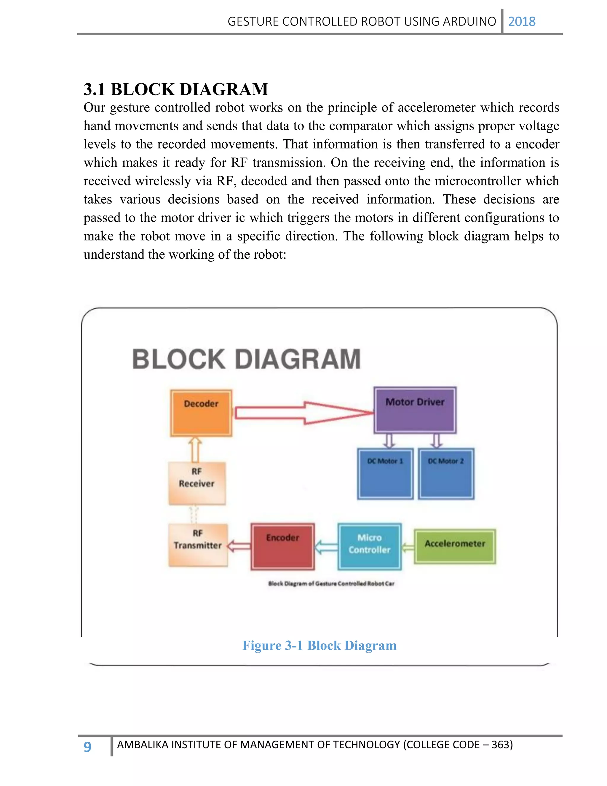
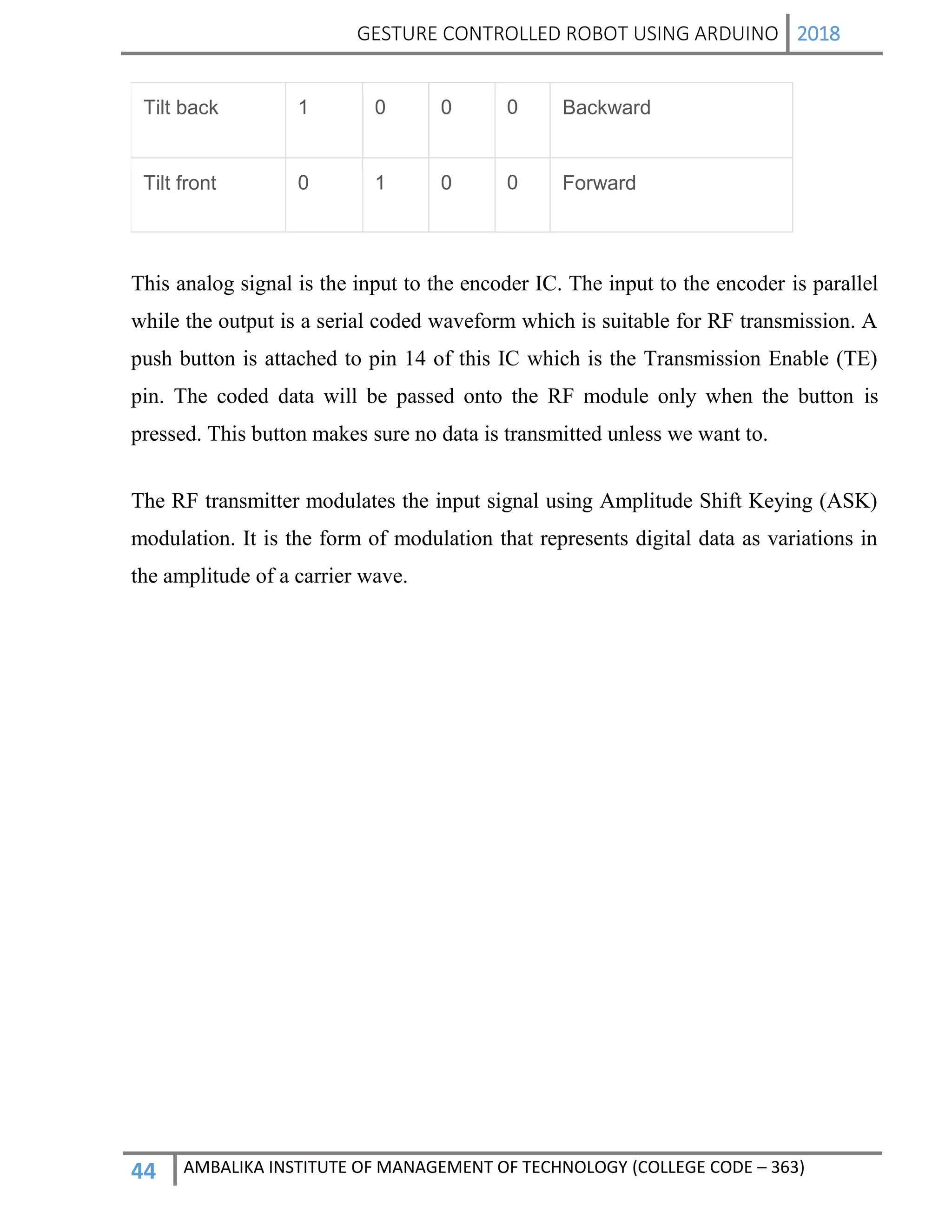
A gesture is a form of non-verbal communication in which visible bodily actions
communicate particular messages, either in place of speech or together and in parallel
with words. Gestures include movement of the hands, face, or other parts of the body.
Gestures differ from physical non-verbal communication that does not communicate
specific messages, such as purely expressive displays, proxemics, or displays of joint
attention. Gestures allow individuals to communicate a variety of feelings and
thoughts, from contempt and hostility to approval and affection, often together with
body language in addition towards when they speak.
Gesture Controlled Robot is a robot which can be controlled by simple gestures. The
user just needs to wear a gesture device which includes a sensor. The sensor will
record the movement of hand in a specific direction which will result in the
movement of the robot in the respective direction. The robot and the Gesture device
are connected wirelessly via radio waves. The wireless communication enables the
user to interact with the robot in a more friendly way.
For more assistance, mail me at pragyakulshresth@gmail.com
Project Report on Hand gesture controlled robot part 1Pragya
A gesture is a form of non-verbal communication in which visible bodily actions
communicate particular messages, either in place of speech or together and in parallel
with words. Gestures include movement of the hands, face, or other parts of the body.
Gestures differ from physical non-verbal communication that does not communicate
specific messages, such as purely expressive displays, proxemics, or displays of joint
attention. Gestures allow individuals to communicate a variety of feelings and
thoughts, from contempt and hostility to approval and affection, often together with
body language in addition towards when they speak.
Gesture Controlled Robot is a robot which can be controlled by simple gestures. The
user just needs to wear a gesture device which includes a sensor. The sensor will
record the movement of hand in a specific direction which will result in the
movement of the robot in the respective direction. The robot and the Gesture device
are connected wirelessly via radio waves. The wireless communication enables the
user to interact with the robot in a more friendly way.
For more assistance, mail me at pragyakulshresth@gmail.com
This document describes a gesture controlled car that can be operated through hand gestures detected by an accelerometer worn on the hand. It consists of an accelerometer, microcontroller, motor driver, motors, RF module, encoder and decoder ICs. The accelerometer senses hand tilts and generates control signals to move the car in four directions. This technology allows for more natural interaction than traditional interfaces and has applications in entertainment, remote control, industrial control, military robotics and medical surgery. Gesture control is expected to become more advanced and widespread with further technological progress.
Human detection robot based on IR radiation emission from human body. It can also detect poison gas content .It is based on IOT technology. It uses PIR sensor, gas sensor, ultrasonic sensor, etc. the IOT technology is implemented using Wi-Fi module and Bluetooth module . Temperature and humidity can also be measured using DHT11 sensor.
The document discusses the development of a gesture-controlled robot. It describes how the robot works using an accelerometer to detect hand gestures, an encoder and transmitter to wirelessly send the gesture data, a receiver and decoder to interpret the data, and a microcontroller and motor driver to control motors based on the gestures. The robot is intended to help disabled people control devices with gestures instead of physical inputs. The system aims to provide a simple and affordable design for potential wide applications.
Gesture control robot using by ArdiunoSudhir Kumar
The document describes a gesture controlled robot project. The objective is to create a simple and inexpensive device that can be mass produced to help disabled people maneuver wheelchairs without touching the wheels. The robot uses an accelerometer to detect hand gestures which are sent to a microcontroller via an RF transmitter/receiver. The microcontroller controls motors via a motor driver to move the robot in corresponding directions based on the gestures.
This document describes a gesture controlled robot that is controlled through hand movements detected by an accelerometer in a glove. The accelerometer outputs analog data related to hand movements which is transmitted via RF to the robot. The robot contains an Arduino, motor driver, receiver module and chassis. It will move forward, backward, left or right depending on the hand gesture detected such as tilting the hand front, back, left or right.
This document describes an obstacle avoiding car project created by Utkarsh Bingewar, Shubham Thakur, and Rupesh Rote, with guidance from their assistant professor Mrs. Varsha Nanaware. The car uses an ultrasonic sensor and Arduino board to detect obstacles and navigate around them. When an obstacle is detected, the Arduino controls the motors to turn the car left or right to avoid the obstacle. The obstacle avoiding car has applications in areas like surveillance, hazardous environments, and unmanned vehicle navigation.
This project report summarizes the design and working of a line follower robot. It discusses the components used including an LM324 comparator IC, AT89C51 microprocessor, L293D H-bridge motor driver, and IR transmitter and receiver. It explains how the IR sensors detect the line and the microprocessor controls the motors to follow the line by turning when sensors detect line edges. The working principle section describes the robot's line detection and movement logic in detail. Applications mentioned include industrial transport, automated vehicles, and museum tour guides.
This document describes a project to build a voice-operated wheelchair for physically disabled persons. The objective is to design hardware for voice recognition and corresponding wheelchair actions. Group members include Mandar Jadhav, Mayuresh Todkar and Dayanand Patil, guided by Dr. V. Jayashree. The system is aimed to help those paralyzed below the neck or with quadriplegia. It will allow independent wheelchair movement through voice commands without need for personal assistance. The design uses a microphone, voice recognition IC, microcontroller, motor drivers and batteries to power DC motors for forward, reverse, left and right wheelchair movement.
New development in sensors, radar and ultrasonic technologies has proved to be a boon for electronics
travelling aids (ETAs). These devices are widely used by blind and physically challenged peoples. C5 laser
cane, Mowat sensor, belt and binaural sonic aid, NAV guide cane are among popular electronic travelling
aids used by blind peoples. For physically challenged person electric wheel chairs controlled by joystick,
eye movement and voice recognition are also available but they have their own limitation in terms of
operating complexity, noise environment and cost. Our paper proposes an automated innovative
wheelchair controlled by neck position of person. It uses simple LEDs, photo sensor, motor and
microcontroller to control the movement of wheelchair
This document is an obstacle avoiding car project report submitted by three students - Utkarsh Bingewar, Shubham Thakur, and Rupesh Rote - to partially fulfill their project requirements for a bachelor's degree in electronics and telecommunications engineering. The report describes the design and implementation of a robotic vehicle that uses an ultrasonic sensor and microcontroller to detect and avoid obstacles in its path by controlling two DC motors through a motor driver. Experimental results show the car is able to successfully detect and navigate around obstacles.
This document summarizes a vehicle starter system that uses fingerprint recognition technology. It begins with an introduction to biometrics and fingerprints, explaining that fingerprints are unique patterns on human fingers. It then provides details on how fingerprint recognition works in vehicles, including the hardware and software components involved. Some key advantages are that fingerprint recognition provides highly reliable and secure access control for vehicles. It also lists potential applications for this technology in cars, motorcycles, and other vehicles. In the end, it evaluates the additional costs of integrating fingerprint recognition systems into some vehicle models.
Robotic Arm using flex sensor and servo motorjovin Richard
The document describes the design and functioning of a robotic arm that can be controlled through hand gestures. The robotic arm has several degrees of freedom and uses sensors like accelerometers and flex sensors to capture hand movements. The analog sensor signals are processed by a microcontroller to generate PWM signals that control servo motors for joint movement. A DC motor is used for the gripper part to pick and place objects. The robotic arm has applications in industrial automation and medical procedures.
This document describes a war field spying robot with a night vision wireless camera. The robot is designed to remotely monitor areas using an RF wireless network and transmit real-time video, even in darkness, using an onboard camera. It is controlled remotely via an RF transmitter and receiver and uses an 8051 microcontroller. The robot is intended to help with spying and reconnaissance in war fields and other hazardous environments.
This document is a 31-page report on a gesture controlled car project submitted for a bachelor's degree. It includes sections on introduction, literature review, implementation, conclusion, and feasibility analysis. The project aims to create a car that can be controlled wirelessly through hand gestures detected by an accelerometer sensor worn on a glove. Forward, backward, left, and right movements are mapped to gestures to remotely drive the car.
The document describes a firefighting robot that is designed to help extinguish fires and reduce risks to human firefighters. It uses sensors like infrared sensors to detect fires and water tanks to help put out flames. The robot is controlled remotely and can navigate autonomously using six legs. It has advantages like reducing risks to firefighters and allowing access to dangerous areas. However, it also has limitations like not being able to operate for long periods without recharging and not being able to replace human firefighters for large fires. The robot aims to help detect fires quickly and minimize financial losses and threats to human life.
This document describes a fingerprint-based security system using an Arduino Uno microcontroller and fingerprint sensor module. It provides an introduction to fingerprint biometrics and explains the components of the system, including how fingerprints are captured and matched. The system is capable of enrollment and verification of fingerprints to control access and will trigger different outputs like a buzzer or motor depending on if a match is found or not. Potential applications of this technology include security systems, employee verification, and border control.
A short PowerPoint presentation on robotic arm, its features and its development. Contains a video explanation, please download to watch it....Thanks for watching.
It consisting Mobile app, Arduino, Bluetooth Receiver module, L293D ic etc. The movement of robot is controlled by the voice which catch by the microphone inside the mobile.
A report on ultrasonic distance measurementitfakash
The document describes an ultrasonic distance meter circuit. It consists of a microcontroller that encodes and transmits ultrasonic pulses via a transmitter. When the pulses reflect off an object, a receiver detects the echo and the microcontroller calculates the distance based on the time elapsed. It displays the measured distance on an LCD screen. The circuit uses various components like a voltage regulator, microcontroller, LCD, buzzer, and ultrasonic transducers to transmit pulses, receive echoes, and determine distances to objects.
Fire Detector and Extinguisher Robot is operated to detect the fire and also to extinguish it. It can be operated in two modes one is manual mode and other is autonomous mode. Manual mode is operated using joysticks and for autonomous mode there is no human intervention. In manual mode direction of the robot is controlled using joysticks, even pump is operated manually. In autonomous mode IR sensors are used to detect the fire and robot is coded accordingly to move in the direction of detected fire. In this robot has a switch which is used to switch between manual and autonomous mode.
Slide show demonstrating pick and place robot and its parts.
Also effects are implanted in the slide.
It can be helpful for students for academic projects.
This is a project report on Smart Dustbin Using IOT Prepared By Lakshya Pandey, Second Year Electrical Engineering Student of Bipin Tripathi Kumaon Institute of Technology (BTKIT), Dwarahat
All Rights Reserved.
IRJET- An Approach to Accelerometer based Controlled RobotIRJET Journal
This document describes a proposed approach for an accelerometer-based controlled robot. The robot will use hand gestures detected by an accelerometer to move in different directions (left, right, forward, backward). The robot will consist of several modules including a hand gesture module using an accelerometer and Arduino UNO, an auto drive module to control movement using signals from the hand gesture module, a voice interaction module using a camera for communication, and a robotic arm module to perform pick and place tasks. The approach aims to allow control of the robot's movement and functions through hand gestures without physical contact for applications such as assisting handicapped individuals.
Vehicle Controlled by Hand Gesture Using Raspberry piIRJET Journal
This document describes a vehicle control system using hand gestures detected by a Raspberry Pi Pico microcontroller. The system includes a glove with an accelerometer that detects the hand movements. The movements are transmitted via RF to a receiver connected to an Arduino and motor driver. The Arduino interprets the hand gestures and sends signals to the motor driver to control the vehicle's direction. The goal is to allow disabled users to control a vehicle intuitively with hand motions instead of buttons.
The document describes a gesture controlled robot that can be operated wirelessly through hand gestures detected by sensors in a glove. The robot uses an accelerometer and wireless transmission modules to receive gesture commands from the glove and control motors to move in the corresponding directions. It aims to allow intuitive control of the robot without remote controls. The methodology discusses the wireless transmission between the glove and robot, including radio frequency transmission and reception modules, and a microcontroller that interprets the commands and controls motors through an motor driver circuit. The scope outlines several potential applications of gesture controlled robots, such as for disabled users, industrial tasks, and entertainment.
This document describes the design of a bionic fist project using a microprocessor and microcontroller. The project aims to create an affordable robotic hand prototype for tele surgery using haptic technology. The hand movements are controlled via flex sensors on a glove that detect finger movements. The circuit diagram and components used include an Arduino, servos, flex sensors and other basic electronic parts. Existing similar projects are reviewed along with their limitations. The scope and working of the proposed bionic fist project is explained, detailing how finger gestures detected by the glove are processed and used to control the robotic hand movements.
This document describes the development of a smart robotic assistant that operates using both voice and gesture commands from a remote Android device. The robotic assistant has a mechanical arm that can pick up and place objects. It is controlled by an Arduino microcontroller and can perform operations like starting, stopping, moving in different directions, and picking up and placing objects. This robotic assistant has applications for helping elderly people and those with disabilities by performing tasks remotely using voice or gesture commands from a smart device.
This document describes an automated gesture-based wireless wheelchair control system using an accelerometer. The system uses an accelerometer sensor to detect hand gestures which are converted to electrical signals and transmitted wirelessly. The receiver then converts the signals and uses them to control a wheelchair's movement and direction. The system was developed to help paralyzed people move independently using hand gestures to tilt the wheelchair forward, backward, left, right, or stop. It allows for movement over 200 yards and detects obstacles using an ultrasonic sensor.
IRJET- Robotic Vehicle Movement and Arm Control Through Hand Gestures using A...IRJET Journal
This document describes a system for controlling a robotic vehicle and arm through hand gestures using an Arduino microcontroller. An accelerometer and flex sensor attached to the user's hand capture gesture data, which is sent wirelessly via nRF modules to an Arduino on the receiving end. This Arduino controls a robotic arm and vehicle. The arm can pick and place objects using a soft gripper, and the vehicle can move in four directions. The goal is to help physically impaired users interact with and manipulate their environment through intuitive hand gestures.
Technology, is today, imbibed for accomplishment of several tasks of varied complexity, in almost all walks of life. The society as a whole is exquisitely dependent on science and technology. Technology has played a very significant role in improving the quality of life. One way through which this is done is by automating several tasks using complex logic to simplify the work.Gesture recognition has been a research area which received much attention from many research communities such as human computer interaction and image processing The keyboard and mouse are currently the main interfaces between man and computer. In other areas where 3D information is required, such as computer games, robotics and design, other mechanical devices such as roller-balls, joysticks and data-gloves are used. The main motto of this project is to make robot realize the human gesture, thereby it bridge the gap between robot and human. Human gesture enhances human-robot interaction by making it independent from input devices. Robotic system can be controlled manually, or it may be autonomous. Robotic hand can be controlled remotely by hand gesture. Research in this field has taken place, sensing hand movements and controlling robotic arm has been developed.
This document describes a final year project to develop a gesture controlled robotic arm. A team of 4 students will build the robotic arm and a wearable hand glove controller. Sensors in the glove will detect hand gestures which will wirelessly control the motion of the robotic arm. The aim is to allow intuitive human-machine interaction. The robotic arm will use servos for motion and the glove will use flex sensors and an accelerometer to detect gestures. An Arduino microcontroller will process the glove sensor data and send commands to the arm over Bluetooth. Potential applications include industrial tasks like assembly and materials handling.
IRJET - Android Controlled Surveillance Robot with Obstacle Detection using A...IRJET Journal
This document describes an Android controlled surveillance robot with obstacle detection capabilities using an Arduino microcontroller. The robot is remotely controlled via Bluetooth from an Android smartphone app. It uses an ultrasonic sensor to detect obstacles and prevent collisions. The robot carries a camera to allow real-time video surveillance that is streamed to the smartphone. The app interface allows controlling robot movement with arrow buttons or by tilting the phone. The robot aims to provide a low-cost alternative for remote surveillance applications.
IRJET- Robotic Hand Controlling using Flex Sensors and Arduino UNOIRJET Journal
This document describes a robotic hand that is controlled using flex sensors and an Arduino Uno microcontroller. Flex sensors are placed on each finger of a glove to sense finger movement. The flex sensor data is sent to the Arduino Uno which processes the data and sends signals to servo motors controlling each finger of the robotic hand. The robotic hand is able to replicate movements of the human hand wearing the flex sensor glove up to 50 meters away using a wireless module. The design provides a low-cost way to control a robotic hand using flex sensors and microcontroller processing to map human finger motions.
This document describes a proposed system called the Hampered Serving Bot, which aims to help physically challenged people by allowing wheelchair control through either voice recognition or gesture control. The system uses an accelerometer sensor to detect hand gestures and control the wheelchair's movement accordingly. It also uses a mobile application connected to a Bluetooth module to recognize voice commands and send them to a microcontroller to control the wheelchair. The system is intended to help both people who cannot walk but can speak, as well as those who cannot walk or speak. It provides an innovative way to control a wheelchair through natural human gestures or voice without needing one's hands.
This document describes a final year project to build a gesture controlled robotic arm. A team of 4 students will build both a robotic arm and a gesture controlled glove. The arm will have 6 axes of rotation and be able to lift up to 1kg. The glove will contain flex sensors and an accelerometer to detect hand gestures and wirelessly control the arm's movement. The goal is to allow intuitive control of the robotic arm through natural hand gestures. Applications could include industrial tasks like welding or materials handling.
IRJET- Development of Robotic Arm using Arduino and Matlab R2016aIRJET Journal
This document describes the development of a robotic arm using Arduino and MATLAB R2016a. The robotic arm is controlled through a graphical user interface in MATLAB. Commands to move the arm left, right, up, down and to grip or release objects are sent from the GUI to an Arduino Uno board connected to the computer. A camera mounted on the arm allows the user to see the position of objects and guide movements. The arm uses three motors for accurate movement and an object detection system to facilitate pick and place tasks.
The document outlines a proposed final year mini project to develop a gesture-controlled robot. It discusses using hand gestures detected by a wearable sensor to wirelessly control a robot. The objectives are to create a simple and affordable human-machine interface. The methodology involves choosing sensors and a microcontroller, designing mechanical components, developing gesture recognition software, and testing the system. A literature review examines similar prior projects. The proposal provides a timeline, references, circuit diagrams, and prototype photos.
Hand movement controlled robotic vehicle which can be controlled by simple gestures. The user just needs to wear a gesture device which includes a sensor. The sensor will record the movement of hand in a specific direction which will result in the movement of the robot in the respective direction. The robot and the Gesture device are connected wirelessly via radio waves. The wireless communication enables the user to interact with the robot in a more friendly way.
Summer Training Program Report On Embedded system and robot Arcanjo Salazaku
This document describes the design of a wireless controlled robot. It uses two microcontrollers - one as the transmitter section controlled by the user and the other as the receiver section mounted on the robot. The transmitter section encodes the control signals from a 4x4 keypad using an HT12E encoder IC and transmits it using an RF module. The robot receives the signals using an RF module and decodes it using an HT12D decoder IC. It then drives the motors using an L293D motor driver IC to control the robot's movement according to the received signals. The system aims to provide easy and low-cost wireless control of the robot.
Virtual Automation using Mixed Reality and Leap Motion ControlIRJET Journal
This document discusses using leap motion technology and mixed reality to control a robot virtually. It proposes a robot system that can be operated solely through human gestures detected by a leap motion sensor, without any other external devices. The robot's movements and tasks would be displayed to the user through an augmented reality mobile app and virtual reality headset. The system aims to provide an immersive experience for applications like shopping assistance, industrial training simulations, and inquiry-based learning. It describes the robot architecture, use of a controller like Arduino, augmented reality development using Unity 3D, and virtual reality using Google Cardboard. Experimental results showed the gesture controls and mixed reality interfaces worked accurately and provided a realistic experience to the user.
The document discusses industrial robots and automation. It defines an industrial robot as a reprogrammable, multifunctional manipulator designed to move material, parts, tools, or devices through variable programmed motions to perform tasks. Robots can be classified as a form of programmable automation. The document covers various topics related to industrial robots including types of automation, robot components, configurations, drives, and technical features like work volume and precision of movement.
IRJET- Can Robots are Changing the World: A ReviewIRJET Journal
This document summarizes a research paper on robots and how they are changing the world. It discusses how robots are rapidly developing from industrial uses to serving as companions. It proposes a hierarchical probabilistic representation of space that would allow robots to understand their environments in a way that is compatible with human users. This conceptual representation of space would be useful for robots to become familiar with their surroundings and interact in a semantically and socially intelligent manner. The paper reviews robot capabilities, sensors, effectors, software architectures, applications, and debates around machine intelligence and thinking.
Similar to Project Report on Hand gesture controlled robot part 2 (20)
Embedded machine learning-based road conditions and driving behavior monitoringIJECEIAES
Car accident rates have increased in recent years, resulting in losses in human lives, properties, and other financial costs. An embedded machine learning-based system is developed to address this critical issue. The system can monitor road conditions, detect driving patterns, and identify aggressive driving behaviors. The system is based on neural networks trained on a comprehensive dataset of driving events, driving styles, and road conditions. The system effectively detects potential risks and helps mitigate the frequency and impact of accidents. The primary goal is to ensure the safety of drivers and vehicles. Collecting data involved gathering information on three key road events: normal street and normal drive, speed bumps, circular yellow speed bumps, and three aggressive driving actions: sudden start, sudden stop, and sudden entry. The gathered data is processed and analyzed using a machine learning system designed for limited power and memory devices. The developed system resulted in 91.9% accuracy, 93.6% precision, and 92% recall. The achieved inference time on an Arduino Nano 33 BLE Sense with a 32-bit CPU running at 64 MHz is 34 ms and requires 2.6 kB peak RAM and 139.9 kB program flash memory, making it suitable for resource-constrained embedded systems.
Understanding Inductive Bias in Machine LearningSUTEJAS
This presentation explores the concept of inductive bias in machine learning. It explains how algorithms come with built-in assumptions and preferences that guide the learning process. You'll learn about the different types of inductive bias and how they can impact the performance and generalizability of machine learning models.
The presentation also covers the positive and negative aspects of inductive bias, along with strategies for mitigating potential drawbacks. We'll explore examples of how bias manifests in algorithms like neural networks and decision trees.
By understanding inductive bias, you can gain valuable insights into how machine learning models work and make informed decisions when building and deploying them.
Comparative analysis between traditional aquaponics and reconstructed aquapon...bijceesjournal
The aquaponic system of planting is a method that does not require soil usage. It is a method that only needs water, fish, lava rocks (a substitute for soil), and plants. Aquaponic systems are sustainable and environmentally friendly. Its use not only helps to plant in small spaces but also helps reduce artificial chemical use and minimizes excess water use, as aquaponics consumes 90% less water than soil-based gardening. The study applied a descriptive and experimental design to assess and compare conventional and reconstructed aquaponic methods for reproducing tomatoes. The researchers created an observation checklist to determine the significant factors of the study. The study aims to determine the significant difference between traditional aquaponics and reconstructed aquaponics systems propagating tomatoes in terms of height, weight, girth, and number of fruits. The reconstructed aquaponics system’s higher growth yield results in a much more nourished crop than the traditional aquaponics system. It is superior in its number of fruits, height, weight, and girth measurement. Moreover, the reconstructed aquaponics system is proven to eliminate all the hindrances present in the traditional aquaponics system, which are overcrowding of fish, algae growth, pest problems, contaminated water, and dead fish.
Harnessing WebAssembly for Real-time Stateless Streaming PipelinesChristina Lin
Traditionally, dealing with real-time data pipelines has involved significant overhead, even for straightforward tasks like data transformation or masking. However, in this talk, we’ll venture into the dynamic realm of WebAssembly (WASM) and discover how it can revolutionize the creation of stateless streaming pipelines within a Kafka (Redpanda) broker. These pipelines are adept at managing low-latency, high-data-volume scenarios.
Optimizing Gradle Builds - Gradle DPE Tour Berlin 2024Sinan KOZAK
Sinan from the Delivery Hero mobile infrastructure engineering team shares a deep dive into performance acceleration with Gradle build cache optimizations. Sinan shares their journey into solving complex build-cache problems that affect Gradle builds. By understanding the challenges and solutions found in our journey, we aim to demonstrate the possibilities for faster builds. The case study reveals how overlapping outputs and cache misconfigurations led to significant increases in build times, especially as the project scaled up with numerous modules using Paparazzi tests. The journey from diagnosing to defeating cache issues offers invaluable lessons on maintaining cache integrity without sacrificing functionality.
Project Report on Hand gesture controlled robot part 2
1. GESTURE CONTROLLED ROBOT USING ARDUINO 2018
1 AMBALIKA INSTITUTE OF MANAGEMENT OF TECHNOLOGY (COLLEGE CODE – 363)
CHAPTER 1
INTRODUCTION
2. GESTURE CONTROLLED ROBOT USING ARDUINO 2018
2 AMBALIKA INSTITUTE OF MANAGEMENT OF TECHNOLOGY (COLLEGE CODE – 363)
1.1 INTRODUCTION
Recently, strong efforts have been carried out to develop intelligent and natural
interfaces between users and computer based systems based on human gestures.
Gestures provide an intuitive interface to both human and computer. Thus, such
gesture-based interfaces can not only substitute the common interface devices, but
can also be exploited to extend their functionality.
Robots are playing an important role in automation across all the sectors like
construction, military, medical, manufacturing, etc. After making some basic robots
like line follower robot, computer controlled robot, etc; we have developed this
accelerometer based gesture controlled robot by using Arduino Uno. In this project
we have used hand motion to drive the robot. For this purpose we have used
accelerometer which works on acceleration.
A gesture controlled robot is controlled by using hand in place of any other method
like buttons or joystick. Here one only needs to move hand to control the robot. A
transmitting device is used in your hand which contains RF Transmitter and accelero-
meter. This will transmit command to robot so that it can do the required task like
moving forward, reverse, turning left, turning right and stop. All these tasks will be
performed by using hand gesture.
Here the most important component is accelerometer. Accelerometer is a 3 axis
acceleration measurement device with ±3g range. This device is made by using
polysilicon surface sensor and signal conditioning circuit to measure acceleration.
The output of this device is Analog in nature and proportional to the acceleration.
This device measures the static acceleration of gravity when we tilt it and gives a
result in form of motion or vibration.
According to the datasheet of adxl335 polysilicon surface-micromachined structure
placed on top of silicon wafer. Polysilicon springs suspend the structure over the
surface of the wafer and provide a resistance against acceleration forces. Deflection
of the structure is measured using a differential capacitor which incorporate
independent fixed plates and plates attached to the moving mass. The fixed plates are
driven by 180° out-of-phase square waves. Acceleration deflects the moving mass
and unbalances the differential capacitor resulting in a sensor output whose
amplitude is proportional to acceleration. Phase-sensitive demodulation techniques
are then used to determine the magnitude and direction of the acceleration.
3. GESTURE CONTROLLED ROBOT USING ARDUINO 2018
3 AMBALIKA INSTITUTE OF MANAGEMENT OF TECHNOLOGY (COLLEGE CODE – 363)
1.2 ROBOT
A robot is usually an electro-mechanical machine that can perform tasks
automatically. Some robots require some degree of guidance, which may be done
using a remote control or with a computer interface. Robots can be autonomous,
semi-autonomous or remotely controlled. Robots have evolved so much and are
capable of mimicking humans that they seem to have a mind of their own.
1.3 HUMAN MACHINE INTERACTION
An important aspect of a successful robotic system is the Human-Machine
interaction. In the early years the only way to communicate with a robot was to
program which required extensive hard work. With the development in science and
robotics, gesture based recognition came into life. Gestures originate from any bodily
motion or state but commonly originate from the face or hand. Gesture recognition
can be considered as a way for computer to understand human body language. This
has minimized the need for text interfaces and GUIs (Graphical User Interface)
Gesture controlled robot moves according to hand movement as we place transmitter
in our hand. When we tilt hand in front side, robot start to moving forward and
continues moving forward until next command is given.
When we tilt hand in backward side, robot change its state and start moving in
backwards direction until other command is given.
When we tilt it in left side Robot get turn left till next command.
When we tilt hand in right side robot turned to right.
And for stopping robot we keeps hand in stable..
1.4 GESTURE
A gesture is an action that has to be seen by someone else and has to convey some
piece of information. Gesture is usually considered as a movement of part of the
body, esp. a hand or the head, to express an idea or meaning.
1.5 MOTIVATION FOR PROJECT
Our motivation to work on this project came from a disabled person who was driving
his wheel chair by hand with quite a lot of difficulty. So we wanted to make a device
which would help such people drive their chairs without even having the need to
touch the wheels of their chairs.
1.6 OBJECTIVE OF PROJECT
Our objective is to make this device simple as well as cheap so that it could be mass
produced and can be used for a number of purposes
4. GESTURE CONTROLLED ROBOT USING ARDUINO 2018
4 AMBALIKA INSTITUTE OF MANAGEMENT OF TECHNOLOGY (COLLEGE CODE – 363)
CHAPTER 2
GESTURE CONTROLLED ROBOT
5. GESTURE CONTROLLED ROBOT USING ARDUINO 2018
5 AMBALIKA INSTITUTE OF MANAGEMENT OF TECHNOLOGY (COLLEGE CODE – 363)
2.1 GESTURE CONTROLLED ROBOT
Gesture recognition technologies are much younger in the world of today. At this
time there is much active research in the field and little in the way of publicly
available implementations .Several approaches have been developed for sensing
gestures and controlling robots. Glove based technique is a well-known means of
recognizing hand gestures. It utilizes a sensor attached to a glove that directly
measures hand movements.
A Gesture Controlled robot is a kind of robot which can be controlled by hand
gestures and not the old fashioned way by using buttons. The user just needs to wear
a small transmitting device on his hand which includes a sensor which is an
accelerometer in our case. Movement of the hand in a specific direction will transmit
a command to the robot which will then move in a specific direction. The
transmitting device includes a Comparator IC for assigning proper levels to the input
voltages from the accelerometer and an Encoder IC which is used to encode the four
bit data and then it will be transmitted by an RF Transmitter module.
At the receiving end an RF Receiver module will receive the encoded data and
decode it by using a decoder IC. This data is then processed by a microcontroller and
passed onto a motor driver to rotate the motors in a special configuration to make the
robot move in the same direction as that of the hand.
6. GESTURE CONTROLLED ROBOT USING ARDUINO 2018
6 AMBALIKA INSTITUTE OF MANAGEMENT OF TECHNOLOGY (COLLEGE CODE – 363)
2.2 ROLE OF ROBOT
Robots are playing an important role in automation across all the sectors like
construction, military, medical, manufacturing, etc. After making some basic robots
like line follower robot, computer controlled robot, etc; we have developed this
accelerometer based gesture controlled robot by using Arduino Uno. In this project
we have used hand motion to drive the robot. For this purpose we have used
accelerometer which works on acceleration.
A gesture controlled robot is controlled by using hand in place of any other method
like buttons or joystick. Here one only needs to move hand to control the robot. A
transmitting device is used in your hand which contains RF Transmitter and accelero-
meter. This will transmit command to robot so that it can do the required task like
moving forward, reverse, turning left, turning right and stop. All these tasks will be
performed by using hand gesture.
Here the most important component is accelerometer. Accelerometer is a 3 axis
acceleration measurement device with ±3g range. This device is made by using
polysilicon surface sensor and signal conditioning circuit to measure acceleration.
The output of this device is Analog in nature and proportional to the acceleration.
This device measures the static acceleration of gravity when we tilt it and gives a
result in form of motion or vibration.
2.2 APPLICATIONS
Through the use of gesture recognition, remote control with the wave of a hand
of various devices is possible.
Gesture controlling is very helpful for handicapped and physically disabled
people to achieve certain tasks, such as driving a vehicle.
Gestures can be used to control interactions for entertainment purposes such as
gaming to make the game player's experience more interactive or immersive.
Traditional interfaces, keyboards and mice present a bottleneck in application
that rely on heavy interaction of the user with the machine due to the
unnaturalness of the interaction.
From reading lots of related articles, we have learnt that recent efforts have
attempted to eliminate this bottleneck by developing different ways of
interacting with computers, for example: speech, handwriting.
7. GESTURE CONTROLLED ROBOT USING ARDUINO 2018
7 AMBALIKA INSTITUTE OF MANAGEMENT OF TECHNOLOGY (COLLEGE CODE – 363)
Through the use of gesture recognition, remote control with the wave of a hand
of various devices is possible.
Gesture controlling is very helpful for handicapped and physically disabled
people to achieve certain tasks, such as driving a vehicle.
Gestures can be used to control interactions for entertainment purposes such as
gaming to make the game player's experience more interactive or immersive.
8. GESTURE CONTROLLED ROBOT USING ARDUINO 2018
8 AMBALIKA INSTITUTE OF MANAGEMENT OF TECHNOLOGY (COLLEGE CODE – 363)
CHAPTER 3
LITERATURE REVIEW
9. GESTURE CONTROLLED ROBOT USING ARDUINO 2018
9 AMBALIKA INSTITUTE OF MANAGEMENT OF TECHNOLOGY (COLLEGE CODE – 363)
3.1 BLOCK DIAGRAM
Our gesture controlled robot works on the principle of accelerometer which records
hand movements and sends that data to the comparator which assigns proper voltage
levels to the recorded movements. That information is then transferred to a encoder
which makes it ready for RF transmission. On the receiving end, the information is
received wirelessly via RF, decoded and then passed onto the microcontroller which
takes various decisions based on the received information. These decisions are
passed to the motor driver ic which triggers the motors in different configurations to
make the robot move in a specific direction. The following block diagram helps to
understand the working of the robot:
Figure 3-1 Block Diagram
10. GESTURE CONTROLLED ROBOT USING ARDUINO 2018
10 AMBALIKA INSTITUTE OF MANAGEMENT OF TECHNOLOGY (COLLEGE CODE – 363)
We divided our task into two parts to make the task easy and simple and to avoid
complexity and make it error free. The first is the transmitting section which includes
the following components:
Accelerometer
Comparator IC
Encoder IC
RF Transmitter Module
The second is the receiving end which comprises of following main components:
RF Receiver Module
Decoder IC
Arduino
Motor Driver IC
DC Geared Motors
3.2 BLOCK DIAGRAM DESCRIPTION
Accelerometer placed on the hand sensed the tilt made by the hand.
Accelerometer capable of measuring how fast the speed of object is changing.
This tilt corresponded to the analog voltage.
Using this voltage, control signals are generated for four directions of the robot
car.
11. GESTURE CONTROLLED ROBOT USING ARDUINO 2018
11 AMBALIKA INSTITUTE OF MANAGEMENT OF TECHNOLOGY (COLLEGE CODE – 363)
3.3 FEATURES
Traditional interfaces, keyboards and mice present a bottleneck in application
that rely on heavy interaction of the user with the machine due to the
unnaturalness of the interaction.
From reading lots of related articles, we have learnt that recent efforts have
attempted to eliminate this bottleneck by developing different ways of
interacting with computers, for example: speech, handwriting.
Through the use of gesture recognition, remote control with the wave of a hand
of various devices is possible.
Gesture controlling is very helpful for handicapped and physically disabled
people to achieve certain tasks, such as driving a vehicle.
Gestures can be used to control interactions for entertainment purposes such as
gaming to make the game player's experience more interactive or immersive.
3.4 COMPONENT DESCRIPTION
3.4.1 ACCELEROMETER (ADXL335)
Figure 3-2 ADXL335 Accelerometer
An Accelerometer is an electromechanical device that measures acceleration forces.
These forces may be static, like the constant force of gravity pulling at your feet, or
they could be dynamic – caused by moving or vibrating the accelerometer. It is a
kind of sensor which record acceleration and gives an analog data while moving in
X,Y,Z direction or may be X,Y direction only depending on the type of the sensor.
12. GESTURE CONTROLLED ROBOT USING ARDUINO 2018
12 AMBALIKA INSTITUTE OF MANAGEMENT OF TECHNOLOGY (COLLEGE CODE – 363)
The ADXL335 is a small, thin, low power, complete 3-axis accelerometer with signal
conditioned voltage outputs. The product measures acceleration with a minimum
full-scale range of ±3 g. It can measure the static acceleration of gravity in tilt-
sensing applications, as well as dynamic acceleration resulting from motion, shock,
or vibration. The user selects the bandwidth of the accelerometer using the CX, CY,
and CZ capacitors at the XOUT, YOUT, and ZOUT pins. Bandwidths can be
selected to suit the application, with a range of 0.5 Hz to 1600 Hz for the X and Y
axes, and a range of 0.5 Hz to 550 Hz for the Z axis. The ADXL335 is available in a
small, low profile, 4 mm × 4 mm × 1.45 mm, 16-lead, plastic lead frame chip scale
package (LFCSP_LQ).
THEORY OF OPERATION
The ADXL335 is a complete 3-axis acceleration measurement system. The
ADXL335 has a measurement range of ±3 g minimum. It contains a polysilicon
surface-micro-machined sensor and signal conditioning circuitry to implement an
open-loop acceleration measurement architecture. The output signals are analog
voltages that are proportional to acceleration. The accelerometer can measure the
static acceleration of gravity in tilt-sensing applications as well as dynamic
acceleration resulting from motion, shock, or vibration. The sensor is a polysilicon
surface-micro-machined structure built on top of a silicon wafer. Polysilicon springs
suspend the structure over the surface of the wafer and provide a resistance against
acceleration forces. Deflection of the structure is measured using a differential
capacitor that consists of independent fixed plates and plates attached to the moving
mass. The fixed plates are driven by 180° out-of-phase square waves. Acceleration
deflects the moving mass and unbalances the differential capacitor resulting in a
sensor output whose amplitude is proportional to acceleration. Phase-sensitive
demodulation techniques are then used to determine the magnitude and direction of
the acceleration.
The demodulator output is amplified and brought off-chip through a 32 kΩ resistor.
The user then sets the signal bandwidth of the device by adding a capacitor. This
filtering improves measurement resolution and helps prevent aliasing.
13. GESTURE CONTROLLED ROBOT USING ARDUINO 2018
13 AMBALIKA INSTITUTE OF MANAGEMENT OF TECHNOLOGY (COLLEGE CODE – 363)
MECHANICAL SENSOR
The ADXL335 uses a single structure for sensing the X, Y, and Z axes. As a result,
the three axes’ sense directions are highly orthogonal and have little cross-axis
sensitivity. Mechanical misalignment of the sensor die to the package is the chief
source of cross-axis sensitivity. Mechanical misalignment can, of course, be
calibrated out at the system level.
PERFORMANCE
Rather than using additional temperature compensation circuitry, innovative design
techniques ensure that high performance is built in to the ADXL335. As a result,
there is no quantization error or non-monotonic behavior, and temperature hysteresis
is very low (typically less than 3 mg over the −25°C to +70°C temperature range).
APPLICATIONS INFORMATION
POWER SUPPLY DECOUPLING
For most applications, a single 0.1 μF capacitor, CDC, placed close to the ADXL335
supply pins adequately decouples the accelerometer from noise on the power supply.
However, in applications where noise is present at the 50 kHz internal clock
frequency (or any harmonic thereof), additional care in power supply bypassing is
required because this noise can cause errors in acceleration measurement. If
additional decoupling is needed, a 100 Ω (or smaller) resistor or ferrite bead can be
inserted in the supply line. Additionally, a larger bulk bypass capacitor (1 μF or
greater) can be added in parallel to CDC. Ensure that the connection from the
ADXL335 ground to the power supply ground is low impedance because noise
transmitted through ground has a similar effect to noise transmitted through VS.
14. GESTURE CONTROLLED ROBOT USING ARDUINO 2018
14 AMBALIKA INSTITUTE OF MANAGEMENT OF TECHNOLOGY (COLLEGE CODE – 363)
SETTING THE BANDWIDTH USING CX, CY, AND CZ
The ADXL335 has provisions for band limiting the XOUT, YOUT, and ZOUT pins.
Capacitors must be added at these pins to implement low-pass filtering for anti-
aliasing and noise reduction. The equation for the 3 dB bandwidth
or more simply
The tolerance of the internal resistor (RFILT) typically varies as much as ±15% of its
nominal value (32 kΩ), and the bandwidth varies accordingly. A minimum
capacitance. The tolerance of the internal resistor (RFILT) typically varies as much
as ±15% of its nominal value (32 kΩ), and the bandwidth varies accordingly. A
minimum capacitance of 0.0047 μF for CX, CY, and CZ is recommended in all
cases.
FIGURE 3-3
15. GESTURE CONTROLLED ROBOT USING ARDUINO 2018
15 AMBALIKA INSTITUTE OF MANAGEMENT OF TECHNOLOGY (COLLEGE CODE – 363)
PIN NO. SYMBOL FUNCTION
1 ST Sets the sensitivity of the accelerometer
2 Z Records analog data for Z direction
3 Y Records analog data for Y direction
4 X Records analog data for X direction
5 GND Connected to ground for biasing
6 VCC +3.3 volt is applied
Table 3-1 Pin description for Accelerometer
16. GESTURE CONTROLLED ROBOT USING ARDUINO 2018
16 AMBALIKA INSTITUTE OF MANAGEMENT OF TECHNOLOGY (COLLEGE CODE – 363)
FIGURE 3-5
USE WITH OPERATING VOLTAGES OTHER THAN 3 V
The ADXL335 is tested and specified at VS = 3 V; however, it can be powered with
VS as low as 1.8 V or as high as 3.6 V. Note that some performance parameters
change as the supply voltage is varied. The ADXL335 output is ratiometric,
therefore, the output sensitivity (or scale factor) varies proportionally to the supply
voltage. At VS = 3.6 V, the output sensitivity is typically 360 mV/g. At VS = 2 V,
the output sensitivity is typically 195 mV/g. The zero g bias output is also
ratiometric, thus the zero g output is nominally equal to VS/2 at all supply voltages.
The output noise is not ratiometric but is absolute in volts; therefore, the noise
density decreases as the supply voltage increases. This is because the scale factor
(mV/g) increases while the noise voltage remains constant. At VS = 3.6 V, the X-
axis and Y-axis noise density is typically 120 μg/√Hz, whereas at VS = 2 V, the X-
axis and Y-axis noise density is typically 270 μg/√Hz.
17. GESTURE CONTROLLED ROBOT USING ARDUINO 2018
17 AMBALIKA INSTITUTE OF MANAGEMENT OF TECHNOLOGY (COLLEGE CODE – 363)
3.2 COMPARATOR IC (LM324)
The comparator ic compares the analog voltage received from the accelerometer and
compares it with a reference voltage and gives a particular high or low voltage. The
received signal is quite noisy and of various voltage levels. This ic compares those
levels and outputs in the form of 1 or 0 voltage level. This process is called signal
conditioning.
The figure shown below is comparator IC. The pins 1, 7, 8 and 14 are output pins. A
reference voltage is connected to the negative terminal for high output when input is
high or positive terminal for high output when input is low from the LM324 IC.
Figure 3-6 LM324 IC
18. GESTURE CONTROLLED ROBOT USING ARDUINO 2018
18 AMBALIKA INSTITUTE OF MANAGEMENT OF TECHNOLOGY (COLLEGE CODE – 363)
PIN NO. SYMBOL FUNCTION
1 Output 1 Output of 1st
Comparator
2 Input 1- Inverting Input of 1st
Comparator
3 Input1+ Non-Inverting Input of 1st
Comparator
4 VCC Supply Voltage; 5V (up to 32V)
5 Input 2+ Non-Inverting Input of 2nd
Comparator
6 Input 2- Inverting Input of 2nd
Comparator
7 Output 2 Output of 2nd
Comparator
8 Output 3 Output of 3rd
Comparator
9 Input 3- Inverting Input of 3rd
Comparator
10 Input 3+ Non-Inverting Input of 3rd
Comparator
11 Ground Ground (0V)
12 Input 4+ Non-Inverting Input of 4th
Comparator
13 Input 4- Inverting Input of 4th
Comparator
14 Output 4 Output of 4th
Comparator
Table 3-2 Pin description for LM324
19. GESTURE CONTROLLED ROBOT USING ARDUINO 2018
19 AMBALIKA INSTITUTE OF MANAGEMENT OF TECHNOLOGY (COLLEGE CODE – 363)
3.3 ENCODER (HT12E)
HT12E is an encoder integrated circuit of 212
series of encoders. They are paired with
212
series of decoders for use in remote control system applications. It is mainly used
in interfacing RF and infrared circuits. The chosen pair of encoder/decoder should
have same number of addresses and data format. Simply put, HT12E converts the
parallel inputs into serial output. It encodes the 12 bit parallel data into serial for
transmission through an RF transmitter. These 12 bits are divided into 8 address bits
and 4 data bits.
HT12E has a transmission enable pin which is active low. When a trigger signal is
received on TE pin, the programmed addresses/data are transmitted together with the
header bits via an RF or an infrared transmission medium. HT12E begins a 4-word
transmission cycle upon receipt of a transmission enable. This cycle is repeated as
long as TE is kept low. As soon as TE returns to high, the encoder output completes
its final cycle and then stops.
Figure 3-7 ENCODER (HT12E)
20. GESTURE CONTROLLED ROBOT USING ARDUINO 2018
20 AMBALIKA INSTITUTE OF MANAGEMENT OF TECHNOLOGY (COLLEGE CODE – 363)
Table 3-3 Pin description for HT12E
21. GESTURE CONTROLLED ROBOT USING ARDUINO 2018
21 AMBALIKA INSTITUTE OF MANAGEMENT OF TECHNOLOGY (COLLEGE CODE – 363)
3.4 RF MODULE (Rx/Tx)
Radio frequency (RF) is a rate of oscillation in the range of about 3 KHz to 300 GHz,
which corresponds to the frequency of radio waves, and the alternating currents
which carry radio signals.
Although radio frequency is a rate of oscillation, the term "radio frequency" or its
abbreviation "RF" are also used as a synonym for radio – i.e. to describe the use of
wireless communication, as opposed to communication via electric wires
The RF module is working on the frequency of 434 MHz and has a range of 50-80
meters.
Figure 3-8 RF Transmitter
PIN FUNCTION
VCC 5V supply
GND Ground pin
Data
Input from pin 17 of HT12E for data
transmission
Ant A wire attached here works as an antenna
Table 3-3 Pin description for RF Tx
22. GESTURE CONTROLLED ROBOT USING ARDUINO 2018
22 AMBALIKA INSTITUTE OF MANAGEMENT OF TECHNOLOGY (COLLEGE CODE – 363)
Figure 3-9 RF Receiver
PIN FUNCTION
VCC 5V supply
GND Ground pin
Data
Output to pin 14 of HT12D for data
transmission
Ant A wire attached here works as an antenna
Table 4-1 Pin description for RF Rx
23. GESTURE CONTROLLED ROBOT USING ARDUINO 2018
23 AMBALIKA INSTITUTE OF MANAGEMENT OF TECHNOLOGY (COLLEGE CODE – 363)
3.5 DECODER IC (HT12D)
HT12D is a decoder integrated circuit that belongs to 212 series of decoders. This
series of decoders are mainly used for remote control system applications, like
burglar alarm, car door controller, security system etc. It is mainly provided to
interface RF and infrared circuits. They are paired with 212 series of encoders. The
chosen pair of encoder/decoder should have same number of addresses and data
format.
In simple terms, HT12D converts the serial input into parallel outputs. It decodes the
serial addresses and data received by, say, an RF receiver, into parallel data and
sends them to output data pins. The serial input data is compared with the local
addresses three times continuously. The input data code is decoded when no error or
unmatched codes are found. A valid transmission in indicated by a high signal at VT
pin.
HT12D is capable of decoding 12 bits, of which 8 are address bits and 4 are data bits.
The data on 4 bit latch type output pins remain unchanged until new is received.
24. GESTURE CONTROLLED ROBOT USING ARDUINO 2018
24 AMBALIKA INSTITUTE OF MANAGEMENT OF TECHNOLOGY (COLLEGE CODE – 363)
Figure 3-10 HT12D IC
Table 4-2 Pin description for HT12D
25. GESTURE CONTROLLED ROBOT USING ARDUINO 2018
25 AMBALIKA INSTITUTE OF MANAGEMENT OF TECHNOLOGY (COLLEGE CODE – 363)
3.6 MICROCONTROLLER (ARDUINO UNO)
Arduino Uno is a microcontroller board based on the ATmega328P. It has 14 digital
input/output pins (of which 6 can be used as PWM outputs), 6 analog inputs, a 16
MHz quartz crystal, a USB connection, a power jack, an ICSP header and a reset
button. It contains everything needed to support the microcontroller; simply connect
it to a computer with a USB cable or power it with an AC-to-DC adapter or battery to
get started.
"Uno" means one in Italian and was chosen to mark the release of Arduino Software
(IDE) 1.0. The Uno board and version 1.0 of Arduino Software (IDE) were the
reference versions of Arduino, now evolved to newer releases. The Uno board is the
first in a series of USB Arduino boards, and the reference model for the Arduino
platform; for an extensive list of current, past or outdated boards see the Arduino
index of boards.
3.6.1 Power
The Arduino Uno board can be powered via the USB connection or with an
external power supply. The power source is selected automatically.
External (non-USB) power can come either from an AC-to-DC adapter (wall-
wart) or battery. The adapter can be connected by plugging a 2.1mm center-
positive plug into the board's power jack. Leads from a battery can be inserted
in the GND and Vin pin headers of the POWER connector.
The board can operate on an external supply from 6 to 20 volts. If supplied
with less than 7V, however, the 5V pin may supply less than five volts and the
board may become unstable. If using more than 12V, the voltage regulator
may overheat and damage the board. The recommended range is 7 to 12 volts.
26. GESTURE CONTROLLED ROBOT USING ARDUINO 2018
26 AMBALIKA INSTITUTE OF MANAGEMENT OF TECHNOLOGY (COLLEGE CODE – 363)
The power pins are as follows:
Vin: The input voltage to the Arduino/Genuino board when it's using an external
power source (as opposed to 5 volts from the USB connection or other regulated
power source). You can supply voltage through this pin, or, if supplying voltage via
the power jack, access it through this pin.
VT: This pin outputs a regulated 5V from the regulator on the board. The board can
be supplied with power either from the DC power jack (7 - 12V), the USB connector
(5V), or the VIN pin of the board (7-12V). Supplying voltage via the 5V or 3.3V pins
bypasses the regulator, and can damage your board. We don't advise it.
3V3. A 3.3 volt supply generated by the on-board regulator. Maximum current draw
is 50 mA.
GND. Ground pins.
IOREF. This pin on the Arduino/Genuino board provides the voltage reference with
which the microcontroller operates. A properly configured shield can read the IOREF
pin voltage and select the appropriate power source or enable voltage translators on
the outputs to work with the 5V or 3.3V.
Microcontroller ATmega328P
Operating Voltage 5V
Input Voltage (recommended) 7-12V
Input Voltage (limit) 6-20V
Digital I/O Pins 14 (of which 6 provide PWM output)
PWM Digital I/O Pins 6
Analog Input Pins 6
DC Current per I/O Pin 20 mA
DC Current for 3.3V Pin 50 mA
Flash Memory 32 KB (ATmega328P) of which 0.5 KB used by
27. GESTURE CONTROLLED ROBOT USING ARDUINO 2018
27 AMBALIKA INSTITUTE OF MANAGEMENT OF TECHNOLOGY (COLLEGE CODE – 363)
Table 4-3 Arduino Specifications
Memory
The ATmega328 has 32 KB (with 0.5 KB occupied by the bootloader). It also has 2
KB of SRAM and 1 KB of EEPROM (which can be read and written with
the EEPROM library).
Input and Output
See the mapping between Arduino pins and ATmega328P ports. The mapping for the
Atmega8, 168, and 328 is identical.
PIN MAPPING ATmega328P
Each of the 14 digital pins on the Uno can be used as an input or output,
using pinMode(),digitalWrite(), and digitalRead() functions. They operate at 5 volts.
Each pin can provide or receive 20 mA as recommended operating condition and has
an internal pull-up resistor (disconnected by default) of 20-50k ohm. A maximum of
40mA is the value that must not be exceeded on any I/O pin to avoid permanent
damage to the microcontroller.
In addition, some pins have specialized functions:
bootloader
SRAM 2 KB (ATmega328P)
EEPROM 1 KB (ATmega328P)
Clock Speed 16 MHz
LED_BUILTIN 13
Length 68.6 mm
Width 53.4 mm
28. GESTURE CONTROLLED ROBOT USING ARDUINO 2018
28 AMBALIKA INSTITUTE OF MANAGEMENT OF TECHNOLOGY (COLLEGE CODE – 363)
Serial: 0 (RX) and 1 (TX). Used to receive (RX) and transmit (TX) TTL serial data.
These pins are connected to the corresponding pins of the ATmega8U2 USB-to-TTL
Serial chip.
External Interrupts: 2 and 3. These pins can be configured to trigger an interrupt on
a low value, a rising or falling edge, or a change in value. See the attachInterrupt()
function for details.
PWM: 3, 5, 6, 9, 10, and 11. Provide 8-bit PWM output with the analogWrite()
function.
SPI: 10 (SS), 11 (MOSI), 12 (MISO), 13 (SCK). These pins support SPI
communication using the SPI library.
LED: 13. There is a built-in LED driven by digital pin 13. When the pin is HIGH
value, the LED is on, when the pin is LOW, it's off.
TWI: A4 or SDA pin and A5 or SCL pin. Support TWI communication using the
Wire library.
The Uno has 6 analog inputs, labeled A0 through A5, each of which provide 10 bits
of resolution (i.e. 1024 different values). By default they measure from ground to 5
volts, though is it possible to change the upper end of their range using the AREF pin
and the analogReference() function. There are a couple of other pins on the board:
AREF. Reference voltage for the analog inputs. Used with analogReference().
Reset. Bring this line LOW to reset the microcontroller. Typically used to add a reset
button to shields which block the one on the board.
29. GESTURE CONTROLLED ROBOT USING ARDUINO 2018
29 AMBALIKA INSTITUTE OF MANAGEMENT OF TECHNOLOGY (COLLEGE CODE – 363)
Figure 3-11 Arduino
3.6.1 INTERFACING WITH ARDUINO RF MODULE
Wireless Communication in any form has become an essential part of human life
whether it may be short distance T.V Remote or long distance radio communication.
Wireless communication is all about transmission of data wirelessly so that there is
no hassle of any wires and no direct contact with the device itself.
FIGURE 3-12
30. GESTURE CONTROLLED ROBOT USING ARDUINO 2018
30 AMBALIKA INSTITUTE OF MANAGEMENT OF TECHNOLOGY (COLLEGE CODE – 363)
FIGURE 3-13
Receiver Part
The receiver part consists of Arduino UNO and the 434 MHz Receiver module. An
external LED can be used along with a current limiting resistor but on board LED
would be sufficient. The design of the Receiver part is as follows.
The RF Receiver Module consists of 4 – pins: VCC, GND, Data and Antenna. VCC
and GND pins are connected to 3.3V pin of the Arduino and ground respectively.
The data pin is connected to Pin 12 of the Arduino.
An antenna similar to the transmitter module is connected to the antenna pin of the
434 MHz Receiver module. The on board LED which is connected to the 13th pin of
Arduino is used in the project although an external LED can always be used.
31. GESTURE CONTROLLED ROBOT USING ARDUINO 2018
31 AMBALIKA INSTITUTE OF MANAGEMENT OF TECHNOLOGY (COLLEGE CODE – 363)
Working Process
In this project, a simple demonstration of RF Communication with the help of
Arduino UNO boards is given. The aim of the project is to successfully transmit data
between the RF Transmitter – Receiver modules using two Arduino UNO
microcontroller boards. The working of the project is explained here.
Note: The project can be implemented with or without the help
of a special library called “VirtualWire.h”. The project
implemented here uses the library. If we want to implement the
project without the library, then we need to change the receiver
part of the circuit.
VirtualWire.h is a special library for Arduino created by Mike
McCauley. It is a communication library that allows two
Arduino’s to communicate with each other using RF Module
i.e. transmitter – receiver pair. This library consists of several
functions that are used for configuring the modules,
transmission of data by the transmitter module and data
reception by the receiver module.
In this project, the transmitter simply sends two characters i.e.
it sends the character “1” and with a delay of few seconds, it
sends the character “0”. Whenever the “1” is sent, the LED on
the transmitting side of the project will be turned ON. As this
“1” is transmitted via RF communication, the receiver will
receive the data “1”.
When the receiver receives “1”, the Arduino on the receiver
side of the project will turn ON the LED on its side.
Similarly, when the data “0” is transmitted by the RF
transmitter, the LED on the transmitter side is turned OFF. As
32. GESTURE CONTROLLED ROBOT USING ARDUINO 2018
32 AMBALIKA INSTITUTE OF MANAGEMENT OF TECHNOLOGY (COLLEGE CODE – 363)
a result, the receiver now receives “0” and the LED on the
receiver side is also turned OFF.
Hence, the receiver is imitating the actions of the transmitter.
33. GESTURE CONTROLLED ROBOT USING ARDUINO 2018
33 AMBALIKA INSTITUTE OF MANAGEMENT OF TECHNOLOGY (COLLEGE CODE – 363)
3.6.1 INTERFACING WITH ARDUINO ADXL 335
34. GESTURE CONTROLLED ROBOT USING ARDUINO 2018
34 AMBALIKA INSTITUTE OF MANAGEMENT OF TECHNOLOGY (COLLEGE CODE – 363)
The accelerometer module has 5 pins, namely
1. GND-To be connected to Arduino's GND
2. VCC-To be connected to Arduino's 5V
3. X-To be connected to Analog Pin A5
4. Y-To be connected to Analog Pin A4
5. Z-To be connected to Analog Pin A3
NOTE:
We don't need to power the module from 3.3v because it already has a 5v to 3.3v
converter. Use 2-pin relegate for connecting Vcc and GND. Use a 3-pin relegate for
connecting X, Y & Z outputs. Also connect AREF pin to the 3.3v. This is done to set
the reference voltage to 3.3v because the output of ADXL335 is 3.3v compatible.
3.6.1 INTERFACING WITH ARDUINO MOTOR DRIVER
What is a Motor Driver?
A motor driver is a small Current Amplifier whose function is to take a low-
current control signal and then turn it into a higher-current signal that can drive
a motor. The L293D is a typical Motor Driver which can drive 2 DC motors
simultaneously.
Why Motor Drivers?
Motor Driver ICs are primarily used in autonomous robotics only. Also
most microprocessors operate at low voltages and require a small amount of
current to operate while the motors require a relatively higher voltages and
current. Thus current cannot be supplied to the motors from the
microprocessor. This is the primary need for the motor driver IC.
So if you want to build a rover or a robot using DC motors, then look no further than
L293D Dual H-Bridge Motor Driver.
35. GESTURE CONTROLLED ROBOT USING ARDUINO 2018
35 AMBALIKA INSTITUTE OF MANAGEMENT OF TECHNOLOGY (COLLEGE CODE – 363)
36. GESTURE CONTROLLED ROBOT USING ARDUINO 2018
36 AMBALIKA INSTITUTE OF MANAGEMENT OF TECHNOLOGY (COLLEGE CODE – 363)
3.7 MOTOR DRIVER IC (L293D)
It is also known as H-Bridge or Actuator IC. Actuators are those devices which
actually gives the movement to do a task like that of a motor. In the real world there
are different types of motors available which work on different voltages. So we need
a motor driver for running them through the controller.
The output from the microcontroller is a low current signal. The motor driver
amplifies that current which can control and drive a motor. In most cases, a transistor
can act as a switch and perform this task which drives the motor in a single direction.
Figure 3-10 L293D IC
Turning a motor ON and OFF requires only one switch to control a single motor in a
single direction. We can reverse the direction of the motor by simply reversing its
polarity. This can be achieved by using four switches that are arranged in an
intelligent manner such that the circuit not only drives the motor, but also controls its
direction. Out of many, one of the most common and clever design is a H-bridge
circuit where transistors are arranged in a shape that resembles the English alphabet
"H".
37. GESTURE CONTROLLED ROBOT USING ARDUINO 2018
37 AMBALIKA INSTITUTE OF MANAGEMENT OF TECHNOLOGY (COLLEGE CODE – 363)
Figure 3-11 H-Bridge
As seen in the image, the circuit has four switches A, B, C and D. Turning these
switches ON and OFF can drive a motor in different ways.
When switches A and D are on, motor rotates clockwise.
When B and C are on, the motor rotates anti-clockwise.
When A and B are on, the motor will stop.
Turning off all the switches gives the motor a free wheel drive.
Turning on A & C at the same time or B & D at the same time shorts the entire
circuit. So, never try to do it.
38. GESTURE CONTROLLED ROBOT USING ARDUINO 2018
38 AMBALIKA INSTITUTE OF MANAGEMENT OF TECHNOLOGY (COLLEGE CODE – 363)
3.8 DC MOTORS
A machine that converts DC power into mechanical power is known as a DC motor.
Its operation is based on the principle that when a current carrying conductor is
placed in a magnetic field, the conductor experiences a mechanical force.
DC motors have a revolving armature winding but non-revolving armature magnetic
field and a stationary field winding or permanent magnet. Different connections of
the field and armature winding provide different speed/torque regulation features.
The speed of a DC motor can be controlled by changing the voltage applied to the
armature or by changing the field current.
Figure 3-12 DC Motor
39. GESTURE CONTROLLED ROBOT USING ARDUINO 2018
39 AMBALIKA INSTITUTE OF MANAGEMENT OF TECHNOLOGY (COLLEGE CODE – 363)
3.8.1 DC GEAR MOTOR
A geared DC Motor has a gear assembly devoted to the motor. The speed of motor is
counted in terms of rotations of the shaft per minute and is termed as RPM .The gear
assembly helps in increasing the torque and dropping the speed. Using the correct
arrangement of gears in a gear motor, its speed can be reduced to any required figure.
This concept of reducing the speed with the help of gears and increasing the torque is
known as gear reduction.
Reducing the speed put out by the motor while increasing the quantity of applied
torque is a important feature of the reduction gear trains found in a gear motor. The
decrease in speed is inversely relative to the increase in torque. This association
means that, in this sort of device, if the torque were to double, the speed would
decrease by one half. Small electric motors, such as the gear motor, are able to move
and stand very heavy loads because of these reduction gear trains. While the speed
and ability of larger motors is greater, small electric motors are sufficient to bear
these loads.
Figure 3-13 DC Gear Motor
40. GESTURE CONTROLLED ROBOT USING ARDUINO 2018
40 AMBALIKA INSTITUTE OF MANAGEMENT OF TECHNOLOGY (COLLEGE CODE – 363)
CHAPTER 4
IMPLEMENTATION
41. GESTURE CONTROLLED ROBOT USING ARDUINO 2018
41 AMBALIKA INSTITUTE OF MANAGEMENT OF TECHNOLOGY (COLLEGE CODE – 363)
4.1 INPUT TO ACCELEROMETER (ADXL 335)
Different Hand gestures to make the robot move in specific directions are as follow:
Fig 5-1 Move Forward
Fig 5-2 Move Backward
Fig 5-3 Move Right
42. GESTURE CONTROLLED ROBOT USING ARDUINO 2018
42 AMBALIKA INSTITUTE OF MANAGEMENT OF TECHNOLOGY (COLLEGE CODE – 363)
Fig 5-4 Move Left
The robot only moves when the accelerometer is moved in a specific direction. The
valid movements are as follows:
DIRECTION
ACCELEROMETER
ORIENTATION
Forward +y
Backward -y
Right +x
Left -x
Stop Rest
Table 5-1 Accelerometer Orientation
43. GESTURE CONTROLLED ROBOT USING ARDUINO 2018
43 AMBALIKA INSTITUTE OF MANAGEMENT OF TECHNOLOGY (COLLEGE CODE – 363)
The accelerometer records the hand movements in the X and Y directions only and
outputs constant analog voltage levels. These voltages are fed to the comparator IC
which compares it with the references voltages that we have set via variable resistors
attached to the IC. The levels that we have set are 1.7V and 1.4V. Every voltage
generated by the accelerometer is compared with these and an analog 1 or 0 signal is
given out by the comparator IC.
Fig 4-1 Input and Output of Comparator IC
There are total five conditions for this Gesture controlled Robot which are giving
below:
Movement of
hand
Input for Arduino from
gesture
Side D3 D2 D1 D0 Direction
Stable 0 0 0 0 Stop
Tilt right 0 0 0 1 Turn Right
Tilt left 0 0 1 0 Turn Left
44. GESTURE CONTROLLED ROBOT USING ARDUINO 2018
44 AMBALIKA INSTITUTE OF MANAGEMENT OF TECHNOLOGY (COLLEGE CODE – 363)
Tilt back 1 0 0 0 Backward
Tilt front 0 1 0 0 Forward
This analog signal is the input to the encoder IC. The input to the encoder is parallel
while the output is a serial coded waveform which is suitable for RF transmission. A
push button is attached to pin 14 of this IC which is the Transmission Enable (TE)
pin. The coded data will be passed onto the RF module only when the button is
pressed. This button makes sure no data is transmitted unless we want to.
The RF transmitter modulates the input signal using Amplitude Shift Keying (ASK)
modulation. It is the form of modulation that represents digital data as variations in
the amplitude of a carrier wave.
45. GESTURE CONTROLLED ROBOT USING ARDUINO 2018
44 AMBALIKA INSTITUTE OF MANAGEMENT OF TECHNOLOGY (COLLEGE
CODE – 363)
The following figure shows the modulated output of the RF module:
Fig 4-2 ASK Modulation
The RF modules works on the frequency of 315MHz. It means that
the carrier frequency of the RF module is 315MHz. The RF module
enables the user to control the robot wirelessly and with ease.
46. GESTURE CONTROLLED ROBOT| 2018
25| Ambalilka Institute Of Management And Technology (College Code-363)
The schematic of transmitting end can be seen below:
47. GESTURE CONTROLLED ROBOT| 2018
26| Ambalilka Institute Of Management And Technology (College Code-363)
This transmitted signal is received by the RF receiver, demodulated
and then passed onto the decoder IC. The decoder IC decodes the
coded waveform and the original data bits are recovered. The input is
a serial coded modulated waveform while the output is parallel. The
pin 17 of the decoder IC is the Valid Transmission (VT) pin. A led
can be connected to this pin which will indicate the status of the
transmission. In the case of a successful transmission, the led will
blink.
The parallel data from the encoder is fed to the port 1of the
microcontroller. This data is in the form of bits. The microcontroller
reads these bits and takes decisions on the basis of these bits. What
the microcontroller does is, it compares the input bits with the coded
bits which are burnt into the program memory of the microcontroller
and outputs on the basis of these bits. Port 2 of the microcontroller is
used as the output port. Output bits from this port are forwarded to the
motor driver IC which drives the motors in a special configuration
based on the hand movements.
At a dead stop, a motor produces no voltage. If a voltage is applied
and the motor begins to spin, it will act as a generator that will
produce a voltage that opposes the external voltage applied to it. This
is called Counter Electromotive Force (CEF) or Back Electromotive
Force (Back EMF). If a load stops the motors from moving then the
current may be high enough to burn out the motor coil windings. To
prevent this, flyback diodes are used. They prevent the back emf from
increasing and damaging the motors.
48. GESTURE CONTROLLED ROBOT| 2018
27| Ambalilka Institute Of Management And Technology (College Code-363)
The schematic of receiving end can be seen below:
49. GESTURE CONTROLLED ROBOT| 2018
28| Ambalilka Institute Of Management And Technology (College Code-363)
4.2 SIMULATION
We performed a simulation of our project in PROTEUS and the code
was written in C language using KEIL MICROVISION. We wrote a
code for the microcontroller to run DC motors using the H-Bridge IC
(L293D). In the simulation we sent the relevant data to the
Microcontroller (AT89C51) through switches. The Microcontroller
processed the data and sent the information to the Actuator IC
(L293D). The Actuator IC upon receiving information showed
response by driving the DC motors. The simulation schematic is as
follow:
Figure 4-1 FYP-1 Simulation
52. GESTURE CONTROLLED ROBOT| 2018
31| Ambalilka Institute Of Management And Technology (College Code-363)
CHAPTER 5
CONCLUSION, LIMITATIONS AND FUTURE
WORK
53. GESTURE CONTROLLED ROBOT| 2018
32| Ambalilka Institute Of Management And Technology (College Code-363)
5.1 CONCLUSION
We achieved our objective without any hurdles i.e. the control of a
robot using gestures. The robot is showing proper responses whenever
we move our hand.
For controlling the robot remotely, Holteks’ encoder-decoder pair
(HT12E and HT12D) together with a 433MHz transmitter-receiver
pair is used.
HT12E and HT12D are CMOS ICs with working voltage ranging
from 2.4V to 12V. Encoder HT12E has eight address and another four
address/data lines. The data set on these twelve lines (address and
address/data lines) is serially transmitted when transmit-enable pin TE
is taken low. The data output appears serially on DOUT pin.
The data is transmitted four times in succession. It consists of
differing lengths of positive-going pulses for ‘1’ and ‘0,’ the pulse-
width for ‘0’ being twice the pulse-width for ‘1.’ The frequency of
these pulses may lie between 1.5 and 7 kHz depending on the resistor
value between OSC1 and OSC2 PINS.
54. GESTURE CONTROLLED ROBOT| 2018
33| Ambalilka Institute Of Management And Technology (College Code-363)
Our finished product can be seen in the images below:
Figure 5-5 Robot-1
Figure5-6 Robot-2
55. GESTURE CONTROLLED ROBOT| 2018
34| Ambalilka Institute Of Management And Technology (College Code-363)
Figure 5-7 Robot Wheel
Figure 5-8 Transmitter Circuit
56. GESTURE CONTROLLED ROBOT| 2018
35| Ambalilka Institute Of Management And Technology (College Code-363)
Figure 5-10 Hand Assembly
Figure 5-11 Robot with Hand Assembly
57. GESTURE CONTROLLED ROBOT| 2018
36| Ambalilka Institute Of Management And Technology (College Code-363)
Disadvantages of the Current Gesture
The current gesture recognition system is a vision-based system
which has many disadvantages, Including
Costly solution
Need high resolution cameras
Highly sensitive to noise in image processing (lens
aberrations)
Advantages of Touch less Gesture Recognition
The disadvantages of the vision-based recognition system have been
overcome in the touch-less based Gesture Recognition system.
The advantages of the touch less sensing system are:
Cheaper solution
Easy to develop
Easy to maintain
Easy to replace
Easy to access
Touch-less
58. GESTURE CONTROLLED ROBOT| 2018
37| Ambalilka Institute Of Management And Technology (College Code-363)
5.2 LIMITATIONS AND FUTURE WORK
The on-board batteries occupy a lot of space and are also quite
heavy. We can either use some alternate power source for the
batteries or replace the current DC Motors with ones which
require less power.
Secondly, as we are using RF for wireless transmission, the
range is quite limited; nearly 50-80m. This problem can be
solved by utilizing a GSM module for wireless transmission.
The GSM infrastructure is installed almost all over the world.
GSM will not only provide wireless connectivity but also quite
a large range.
Thirdly, an on-board camera can be installed for monitoring the
robot from faraway places. All we need is a wireless camera
which will broadcast and a receiver module which will provide
live streaming.
59. GESTURE CONTROLLED ROBOT| 2018
38| Ambalilka Institute Of Management And Technology (College Code-363)
REFERENCES
[1] “Gesture Controlled Robot PPT”
<http://seminarprojects.com/s/hand-gesture-controlled-robot-ppt>
[2] “Gesture Controlled Tank Toy User Guide”
<http://www.slideshare.net/neeraj18290/wireless-gesture-controlled-tank-toy-
transmitter>
[3] “Embedded Systems Guide (2002)”
<http://www.webstatschecker.com/stats/keyword/a_hand_gesture_based_cont
rol_interface_for_a _car_robot>
[4] “Robotic Gesture Recognition (1997)” by Jochen Triesch and
Christoph Von Der Malsburg
<http://citeseerx.ist.psu.edu/viewdoc/summary?doi=10.1.1.37.5427>
[5] “Real-Time Robotic Hand Control Using Hand Gestures” by
Jagdish Lal Raheja, Radhey Shyam, G. Arun Rajsekhar and P. Bhanu
Prasad
[6] “Hand Gesture Controlled Robot” by Bhosale Prasad S., Bunage
Yogesh B. and Shinde
Swapnil V.
[7]<http://www.robotplatform.com/howto/L293/motor_driver_1.htm>
[8]< http://en.wikipedia.org/wiki/Gesture_interface>
[9]< http://www.wisegeek.com/what-is-a-gear-motor.htm>
[10]<http://www.scribd.com/doc/98400320/InTech-Real-Time-Robotic-
Hand-Control-Using-Hand-Gestures>
[11]< http://en.wikipedia.org/wiki/DC_motor>
[12]<http://electronics.stackexchange.com/questions/18447/what-is-
back-emf-counter-electromotive-force>