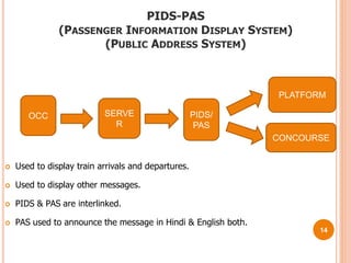
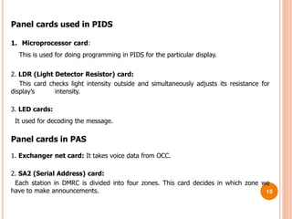
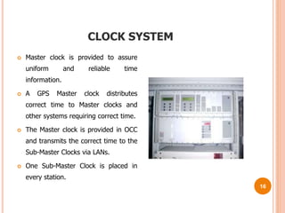
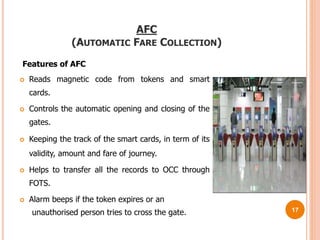
Faculty Head
NAME
Presented By:
NAME
1
A
SUMMER TRAINING
PRESENTATION
ON
CONTENTS
 Introduction
 SCADA
 Communication Flow-Chart
 RTU
 Digital I/P card
 Digital O/P card
 Analog Card
 CPU Card
 SCADA Software
 Application of SCADA
 PIDS-PAS
 Clock System
 AFC Gate 2
INTRODUCTION
METRO is like a dream come true for Delhi, a revolutionary change in the city
transport. Delhi needs metro system in the first place and it would change things
for the better not only for people who would be using it and but for the people
living in Delhi by reducing congestion, air pollution, noise pollution and accidents.
Formation of DMRC
 DMRC was registered on 30.05.1995 under the companies act for construction
and operation of the metro project.
 DMRC is the joint venture of the Government of India and Government of
National Capital Territory of Delhi.
 It started functioning in November, 1997.
 The whole project of approximately 200Kms is to be completed in three phases
up to 2021.
3
SCADA (SUPERVISORY CONTROL AND DATA
ACQUISITION SYSTEM)
Supervision:
Supervision of the traction and auxiliary power system interactively with schematic
pictures which illustrate the real time status of Isolators, Transformers etc. and
direct the operator to make correct decisions.
Control:
The operator performs control operations like open or close the isolators,
interrupters etc.
Data acquisition:
Process information is stored on a process database and a report database in the
form of event list, energy reports and graphs.
4
COMMUNICATION FLOW CHART
5
REMOTE TERMINAL UNIT
1. DIGITAL INPUT CARD (For Monitoring of status)
2. DIGITAL OUTPUT CARD (For Command execution)
3. ANALOG INPUT CARD (For Measurement of analog values)
4. CPU CARD (Communication with Control Centre)
5. POWER SUPPLY CARD
6
DIGITAL INPUT CARD
 Signal proceed in binary form.
 Time resolution is about 1msec.
 It could take signal from circuit breaker
like Close and Open status
Local/Remote Status, Test/Service
status , SF6 Gas Pressure status, Trip
circuit status.
 Signal taken from transformer like Oil
Level Status, Oil Temperature ,Winding
Temperature .
7
DIGITAL OUTPUT CARD
 Processed 16 Binary signals.
 O/p pulse vary from 100msec to
25.5 sec.
 It has 16 relays.
 Each 8 relays are isolated from
other 8 relays.
8
ANALOG I/P CARD
 It supports 8 Analog Inputs at a
time.
 It measure analog values such as
voltage, current, frequency etc.
 It takes input with the help of
transducer.
9
CPU CARD
 Managing and controlling of the I/O –
boards of the RTU peripheral bus.
 Reading process events from the input
boards.
 Writing commands to the output
boards.
 Serial communication with central
systems
 Running the LAF (Local Automation
Function) user application program
 Printing the local log on a printer.
10
SCADA SOFTWARE
11
EVENT LIST
ANY CHANGE IN THE FIELD STATUS OR ANY OPERATOR’S REQUEST OR ACTION SHALL BE PROCESSED AS
AN EVENT AND WILL BE LOGGED ON TO THE EVENT LIST IN CHRONOLOGICAL ORDER.
12
Application areas
SCADA is system for local and remote control applications suitable for
electrical and non-electrical distribution areas.
The SCADA-based electrical application areas are:
• Power transmission and distribution
The SCADA-based non- electrical application areas are:
• Water purification and distribution
• Waste water treatment
• Oil and gas distribution etc.
13
PIDS-PAS
(PASSENGER INFORMATION DISPLAY SYSTEM)
(PUBLIC ADDRESS SYSTEM)
 Used to display train arrivals and departures.
 Used to display other messages.
 PIDS & PAS are interlinked.
 PAS used to announce the message in Hindi & English both.
OCC SERVE
R
PIDS/
PAS
PLATFORM
CONCOURSE
14
Panel cards used in PIDS
1. Microprocessor card:
This is used for doing programming in PIDS for the particular display.
2. LDR (Light Detector Resistor) card:
This card checks light intensity outside and simultaneously adjusts its resistance for
display’s intensity.
3. LED cards:
It used for decoding the message.
Panel cards in PAS
1. Exchanger net card: It takes voice data from OCC.
2. SA2 (Serial Address) card:
Each station in DMRC is divided into four zones. This card decides in which zone we
have to make announcements. 15
CLOCK SYSTEM
 Master clock is provided to assure
uniform and reliable time
information.
 A GPS Master clock distributes
correct time to Master clocks and
other systems requiring correct time.
 The Master clock is provided in OCC
and transmits the correct time to the
Sub-Master Clocks via LANs.
 One Sub-Master Clock is placed in
every station.
16
AFC
(AUTOMATIC FARE COLLECTION)
Features of AFC
 Reads magnetic code from tokens and smart
cards.
 Controls the automatic opening and closing of the
gates.
 Keeping the track of the smart cards, in term of its
validity, amount and fare of journey.
 Helps to transfer all the records to OCC through
FOTS.
 Alarm beeps if the token expires or an
unauthorised person tries to cross the gate. 17
Thank
you
18

DMRC

  • 1.
  • 2.
    CONTENTS  Introduction  SCADA Communication Flow-Chart  RTU  Digital I/P card  Digital O/P card  Analog Card  CPU Card  SCADA Software  Application of SCADA  PIDS-PAS  Clock System  AFC Gate 2
  • 3.
    INTRODUCTION METRO is likea dream come true for Delhi, a revolutionary change in the city transport. Delhi needs metro system in the first place and it would change things for the better not only for people who would be using it and but for the people living in Delhi by reducing congestion, air pollution, noise pollution and accidents. Formation of DMRC  DMRC was registered on 30.05.1995 under the companies act for construction and operation of the metro project.  DMRC is the joint venture of the Government of India and Government of National Capital Territory of Delhi.  It started functioning in November, 1997.  The whole project of approximately 200Kms is to be completed in three phases up to 2021. 3
  • 4.
    SCADA (SUPERVISORY CONTROLAND DATA ACQUISITION SYSTEM) Supervision: Supervision of the traction and auxiliary power system interactively with schematic pictures which illustrate the real time status of Isolators, Transformers etc. and direct the operator to make correct decisions. Control: The operator performs control operations like open or close the isolators, interrupters etc. Data acquisition: Process information is stored on a process database and a report database in the form of event list, energy reports and graphs. 4
  • 5.
  • 6.
    REMOTE TERMINAL UNIT 1.DIGITAL INPUT CARD (For Monitoring of status) 2. DIGITAL OUTPUT CARD (For Command execution) 3. ANALOG INPUT CARD (For Measurement of analog values) 4. CPU CARD (Communication with Control Centre) 5. POWER SUPPLY CARD 6
  • 7.
    DIGITAL INPUT CARD Signal proceed in binary form.  Time resolution is about 1msec.  It could take signal from circuit breaker like Close and Open status Local/Remote Status, Test/Service status , SF6 Gas Pressure status, Trip circuit status.  Signal taken from transformer like Oil Level Status, Oil Temperature ,Winding Temperature . 7
  • 8.
    DIGITAL OUTPUT CARD Processed 16 Binary signals.  O/p pulse vary from 100msec to 25.5 sec.  It has 16 relays.  Each 8 relays are isolated from other 8 relays. 8
  • 9.
    ANALOG I/P CARD It supports 8 Analog Inputs at a time.  It measure analog values such as voltage, current, frequency etc.  It takes input with the help of transducer. 9
  • 10.
    CPU CARD  Managingand controlling of the I/O – boards of the RTU peripheral bus.  Reading process events from the input boards.  Writing commands to the output boards.  Serial communication with central systems  Running the LAF (Local Automation Function) user application program  Printing the local log on a printer. 10
  • 11.
  • 12.
    EVENT LIST ANY CHANGEIN THE FIELD STATUS OR ANY OPERATOR’S REQUEST OR ACTION SHALL BE PROCESSED AS AN EVENT AND WILL BE LOGGED ON TO THE EVENT LIST IN CHRONOLOGICAL ORDER. 12
  • 13.
    Application areas SCADA issystem for local and remote control applications suitable for electrical and non-electrical distribution areas. The SCADA-based electrical application areas are: • Power transmission and distribution The SCADA-based non- electrical application areas are: • Water purification and distribution • Waste water treatment • Oil and gas distribution etc. 13
  • 14.
    PIDS-PAS (PASSENGER INFORMATION DISPLAYSYSTEM) (PUBLIC ADDRESS SYSTEM)  Used to display train arrivals and departures.  Used to display other messages.  PIDS & PAS are interlinked.  PAS used to announce the message in Hindi & English both. OCC SERVE R PIDS/ PAS PLATFORM CONCOURSE 14
  • 15.
    Panel cards usedin PIDS 1. Microprocessor card: This is used for doing programming in PIDS for the particular display. 2. LDR (Light Detector Resistor) card: This card checks light intensity outside and simultaneously adjusts its resistance for display’s intensity. 3. LED cards: It used for decoding the message. Panel cards in PAS 1. Exchanger net card: It takes voice data from OCC. 2. SA2 (Serial Address) card: Each station in DMRC is divided into four zones. This card decides in which zone we have to make announcements. 15
  • 16.
    CLOCK SYSTEM  Masterclock is provided to assure uniform and reliable time information.  A GPS Master clock distributes correct time to Master clocks and other systems requiring correct time.  The Master clock is provided in OCC and transmits the correct time to the Sub-Master Clocks via LANs.  One Sub-Master Clock is placed in every station. 16
  • 17.
    AFC (AUTOMATIC FARE COLLECTION) Featuresof AFC  Reads magnetic code from tokens and smart cards.  Controls the automatic opening and closing of the gates.  Keeping the track of the smart cards, in term of its validity, amount and fare of journey.  Helps to transfer all the records to OCC through FOTS.  Alarm beeps if the token expires or an unauthorised person tries to cross the gate. 17
  • 18.