Downloaded 391 times


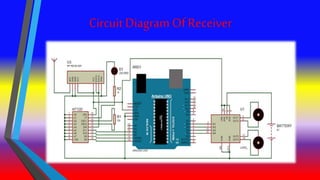
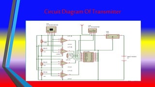
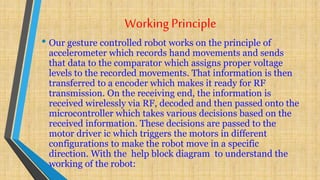
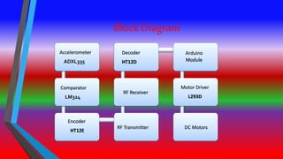

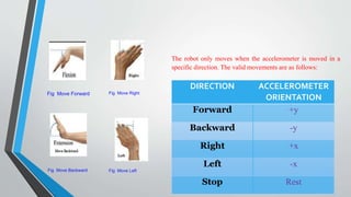
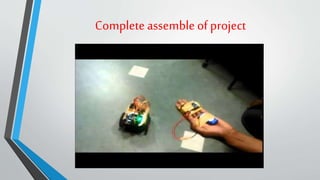


The document describes a gesture controlled robot project. The objective is to create a simple and inexpensive device that can be mass produced to help disabled people maneuver wheelchairs without touching the wheels. The robot uses an accelerometer to detect hand gestures which are sent to a microcontroller via an RF transmitter/receiver. The microcontroller controls motors via a motor driver to move the robot in corresponding directions based on the gestures.


![Getting Started with Apache Spark: Big Data Made Simple [Free Meetup]](https://cdn.slidesharecdn.com/ss_thumbnails/apachesparkgettingstarted-260203175547-8361bcc3-thumbnail.jpg?width=640&height=640&fit=bounds)


