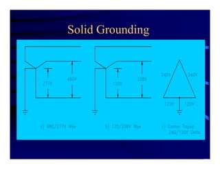
This document discusses various grounding methods for power systems, including solid grounding, ungrounded systems, resistance grounding, and reactance grounding. It provides examples of how each method works and considerations for selecting a grounding approach based on factors like service continuity requirements and the presence of line-to-neutral loads. The document also reviews retrofitting existing systems and includes diagrams demonstrating different grounding configurations.


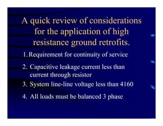

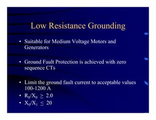
![M.V.-MULTIPLE LOW RESISTANCE
GROUND SOURCES [Author = Powell]](https://image.slidesharecdn.com/ieeesfchaptergroundingpresentation-160202050958/85/Application-Considerations-for-Power-System-Grounding-49-320.jpg)
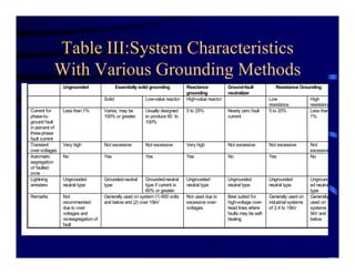
![TYPICAL GENERATOR GROUND FAULT
[Author = Powell]
400a
400a
13.8kV distribution bus](https://image.slidesharecdn.com/ieeesfchaptergroundingpresentation-160202050958/85/Application-Considerations-for-Power-System-Grounding-54-320.jpg)
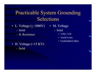
![SYSTEM ARC ENERGY
[Author = Powell]
0 100 200 300 400
0
250
500
750
1000
System
1 10
3
0.01 0.1 1 10
0
250
500
750
1000
System
Faultenergy,watt-seconds
Faultenergy,watt-seconds
Current, amperes Time, seconds
• FIG.7A-ENERGY DUE TO “SYSTEM” -
VARIOUS CURRENT MAGNITUDES
• FIG.7B-ARC ENERGY FOR 400A
R.”SYSTEM”](https://image.slidesharecdn.com/ieeesfchaptergroundingpresentation-160202050958/85/Application-Considerations-for-Power-System-Grounding-55-320.jpg)
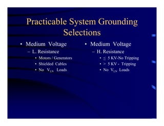
![GEN. ARC ENERGY
[Author = Powell]
• FIG. 8B-FAULT ENERGY FOR 400A
“GEN CURRENT”
• FIG. 8A-FAULT ENERGY DUE TO
“GEN.” FOR VARIOUS CURRENTS
0 100 200 300 400
0
2500
5000
7500
1 10
4
Generator
0.01 0.1 1 10
0
2500
5000
7500
1 10
4
Generator
Faultenergy,watt-seconds
Faultenergy,watt-seconds
Current, amperes Time, seconds](https://image.slidesharecdn.com/ieeesfchaptergroundingpresentation-160202050958/85/Application-Considerations-for-Power-System-Grounding-56-320.jpg)
![FAULT ENERGY WITH 10A GROUNDING
[Author = Powell]
Generator
Faultenergy,watt-seconds
0.01 0.1 1 10
0
25
50
75
100
Time, seconds](https://image.slidesharecdn.com/ieeesfchaptergroundingpresentation-160202050958/85/Application-Considerations-for-Power-System-Grounding-57-320.jpg)
![GENERATOR SOLUTIONS - HYBRID
• GEN. H. R. GROUNDED AND SYSTEM L. R. GROUNDED
[Author=Shipp]
G 59G
51G
LRG
86
R
HRG
* PHASE RELAYS
*](https://image.slidesharecdn.com/ieeesfchaptergroundingpresentation-160202050958/85/Application-Considerations-for-Power-System-Grounding-60-320.jpg)