Downloaded 20 times
![IJRET: International Journal of Research in Engineering and Technology eISSN: 2319-1163 | pISSN: 2321-7308
__________________________________________________________________________________________
Volume: 02 Issue: 08 | Aug-2013, Available @ http://www.ijret.org 362
Sl Level Location Area (sft) Inside Conditions, DB, RHOccupancy
FreshAir
(cfm)
Dehumidifiedair
qty (cfm)
Cooling
load(TR)
Capacity ofAHU's
Proposed
1 GF BMS 465 22Deg C, 55% 4 101 2104 4 4 2200 cfm / 5 TR
2 GF Lift lobby 885 24Deg C, 50% 7 194 2657 7.00 7 3750 cfm / 10 TR
3 GF Entrance Lobby 835 24Deg C, 50% 8 183 2532 7.00 7 3750 cfm / 10 TR
4 GF Society Room 1987 24Deg C, 50% 15 435 4651 12.00 12 3000cfm / 7.5 TR
1 1 Grid BF-2, 12 14500 24Deg C, 50% 190 3178 27656 68.00 68 30000cfm / 65 TR
2 1
Grid FJ-2, 12 +
Grid JP-7,12 15000 24Deg C, 50% 200 3281 21374 57.00 57 26000cfm/ 55 TR
3 2-6 Grid BF-2, 12 14500 24Deg C, 50% 210 3178 24117 63.00 315 30000cfm/ 65 TR
4 2-6
Grid FJ-2, 12 +
Grid JP-7,12 15000 24Deg C, 50% 220 3300 18362 52.00 260 26000cfm/ 55 TR
5 7 Grid BF-2, 12 14500 24Deg C, 50% 190 3178 24097 62.00 62 30000cfm/ 65 TR
6 7
Grid FJ-2, 12 +
Grid JP-7,12 15000 24Deg C, 50% 200 3281 18223 52.00 52 26000cfm/ 55 TR
Total PeakSummer Cooling Load (TR) 844
With diversity factorof0.8 675
Proposed Chillers : 220TR Nominal capacity chillers -4 Nos. (3w*+1s)
* Note : 4thChilleralso shall be working during peak summerto meet the building load. Hence, system is designed considering 4 chillers and 4 pumps working.
Total Load
(TR)
BASIS OFDESIGNFORAIRCONDITIONING SYSTEM FORGANGAHITECHCITY2-SOCIETY, HYDERABAD
5. EQUIPMENT SELECTION
After assessment of Air conditioning load, equipment must be
selected with enough capacity to offset this load. The air
supplied to the space must be of the proper conditions to
satisfy both the sensible and latent loads estimated.
5.1. The Major Equipment Involved In An Central
Air Conditioning System :
• Chillers
• Primary pumps
• Secondary pumps
• Air handling units
a) Air-Cooled Chillers
The Chillers are Energy Efficient and Robust in construction.
They are developed with state of art technology components.
The chillers are fitted with R-134a optimized BitzerCSH3
series Semi-hermetic Screw Compressors, High efficiency DX
Coolers and Aircooled Condensers. The latest generation High
Efficient Copper tubes are incorporated in the Coolers.
Electronic Expansion Valves and the new generation MCS
Magnum Controller lead to precise control of refrigerant flow
and chilled water temperature. Specially developed low noise
Bird Wing design fans are used for optimum air flow.
Acoustic enclosure for compressor can be offered as an
optional feature to reduce noise level. Special coatings on
aluminium condenser fins can also be offered for better
corrosion resistance required in coastal / industrial
environments
6. Air-Cooled Versus Water-Cooled Chillers
Operating Cost:
When compared to water-cooled chillers, air-cooled systems
that function without any condenser water pumps or water
cooling towers require lower initial installation and
maintenance costs. However, lower condensing temperature of
water-cooled chillers can offset this high installation cost.
b) Basic Chilled Water Pumping System
• Single Chiller, Single Constant Speed Pump
• 3-way valves for all Chilled Water Coils (or even more basic
– no valves – full flow) maintains constant flow.
• Control strategy: Enable chilled water pump when outside air
temperature is above
set point and at least 1 chilled water coil control valve is open
to coil. Enable chillerafter flow is proven. Chiller operates to
maintain leaving chilled water temperature atsetpoint. Coil
valves modulate to maintain comfortable space conditions.[7]
7. Basic Primary / Secondary Chilled Water Pumping
System
• Single Chiller, Single Constant Speed Primary Pump, bypass
loop with no valve, Variable Speed Secondary Pump.
• The primary pump pumps water through the chiller. The
secondary pump pulls water from the primary system and
pumps it to the coils.
• Add a Water Differential Pressure Transmitter near the end
of the piping run (in an accessible location).
• VFDs and pumps have minimum recommended operating
speeds,typically about 20%. Use 3-way valves for 1 or more
coils to ensurethat there is always this amount of water
flowing in the secondary loop. My recommendation is to use
3-way valves at units that are expected to have full occupancy
for the most hours and not atGymnasium or other units that
serve areas where significant operating time is at less than full
occupancy (partial / low load areas).
• Control strategy: Enable both primary and secondary chilled
water pumps when outside air temperature is above setpoint
and at least 1chilled water coil control valve is open to coil.
Modulate (vary) thespeed of the secondary pump VFD to
maintain a constant differentialpressure. Enable chiller after
flow is proven. Chiller operates tomaintain leaving chilled
water temperature at setpoint. Coil valvesmodulate to maintain
comfortable space conditions.](https://image.slidesharecdn.com/designofairconditioningandventilationsystemfora-140804003951-phpapp01/75/Design-of-air-conditioning-and-ventilation-system-for-a-3-2048.jpg)
![IJRET: International Journal of Research in Engineering and Technology eISSN: 2319-1163 | pISSN: 2321-7308
__________________________________________________________________________________________
Volume: 02 Issue: 08 | Aug-2013, Available @ http://www.ijret.org 363
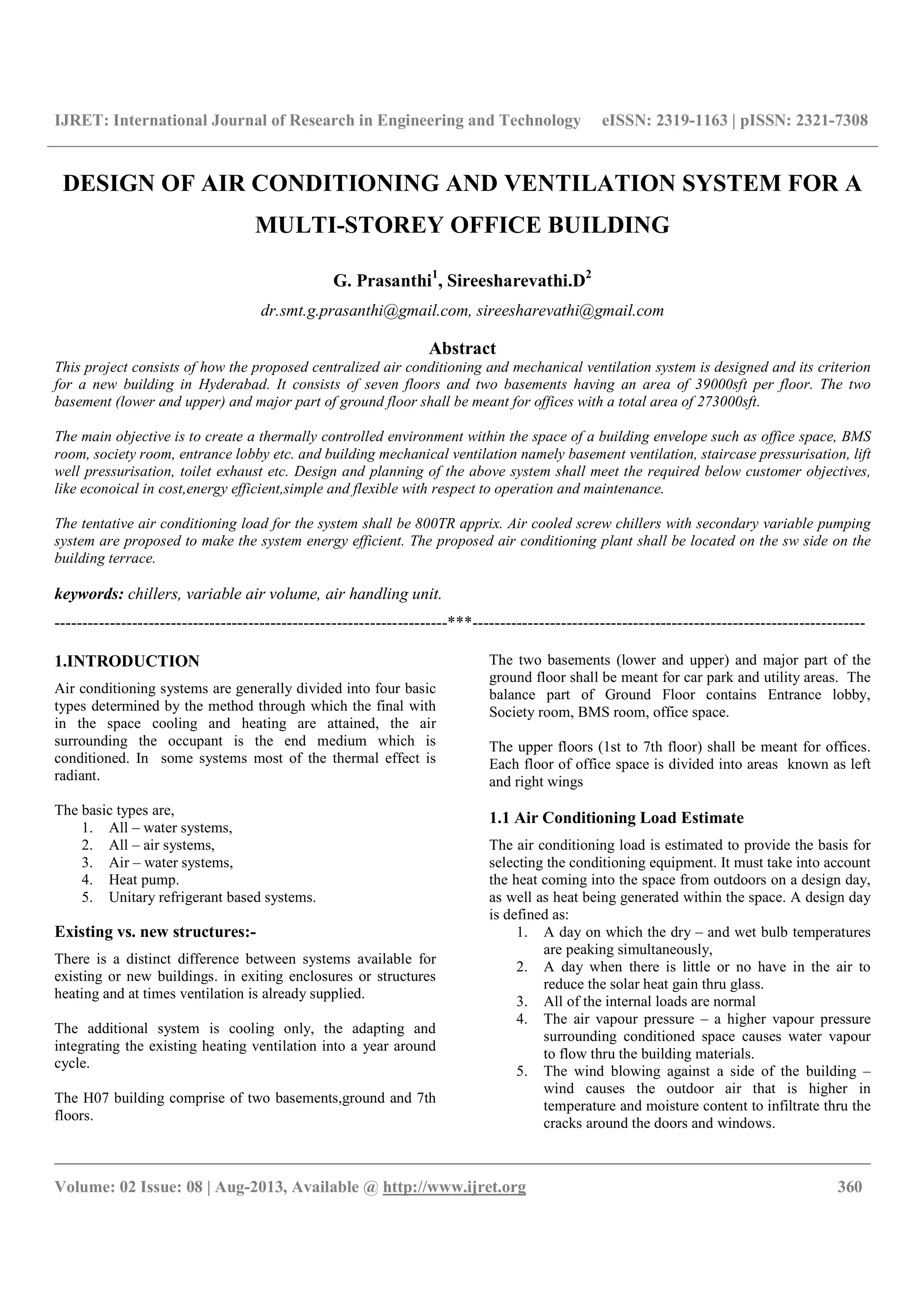
8. VARIABLE VOLUME / VARIABLE SPEED
VARIABLE SPEED PRIMARY CHILLED WATER PUMP
CONTROLWITH TWO WAY VALVE DIRECT RETURN
SYSTEM
DESCRIPTION:
The volume of water supplied to the system is[4] varied in
response to the cooling load by the two-way zone valves. The
basis of variable speed pumping is to save pumping cost by
optimizing the pump motor horsepower input. The pump
produces only the flow and head required at any time. This is
performed by regulation of the pump speed/adjustable
frequency drive and modulation of a bypass valve through the
use of the Technologic™ Controller. The controller regulates
the pump speed and valve position in response to the system
load conditions and in order to protect the pumps and chillers.
Fig . VARIABLE SPEED CHILLED WATER PUMP
CONTROL VARIABLE SPEED PRIMARY SYSTEM WITH
BYPASS AT THE CHILLERS
Reduce Energy Consumption.
Utilizing the variable volume system (two-way terminal
control valves), the pumping energy can be reduced by more
than two-thirds that of a constant speed pumpingsystem riding
its pump curve.
The variable speed system responds to a differential pressure
sensor/transmitter, which is sensing across a terminal and two-
way valve. This allows for energysavings as the terminal
responds to a lighter load and the two-way valves control at a
lower flow position. This increased pressure drop signals the
controller to operate the pump(s) at a lower speed to maintain
its set point.
Applications that operate for a high percentage of time at part
load will utilize the variable speed, energy savings potential of
variable primary systems by loweringspeed, thus consuming
less energy during lighter loads. Those that operate at full load
but with lower that design return water temperature benefit in
a similar manner by slowing down the pumps to an adequate
rate, thus maintaining optimal return temperature, allowing the
chiller(s) to operate more efficiently.
C) Air Handling Apparatus
Air handling apparatus can be of three types
a) Built up apparatus where the casing for the conditioning
equipment is fabricated and installed at or near the job site
b) Fan coil equipment that is manufactured and shipped to the
job site, either completely or partially assembled; and
c) Self-containedequipment which is shipped to the job site
completely assembled.](https://image.slidesharecdn.com/designofairconditioningandventilationsystemfora-140804003951-phpapp01/75/Design-of-air-conditioning-and-ventilation-system-for-a-4-2048.jpg)
![IJRET: International Journal of Research in Engineering and Technology eISSN: 2319-1163 | pISSN: 2321-7308
__________________________________________________________________________________________
Volume: 02 Issue: 08 | Aug-2013, Available @ http://www.ijret.org 364
LOCATION
The location of the air handling apparatus directly influences
the economic and the sound level aspects of any system
9. ECONOMIC CONSIDERATION
The air handling apparatus should be centrally located to
obtain a minimum-first cost system. In a few instances,
however, it maybe be necessary to locate the
apparatus,refrigeration machine,and cooling tower in one area,
to achieve optimum system cost.
When the three components are grouped in one location, the
cost of extra ductwork is offset by the reduced piping cost. In
addition, when the complete system becomes large enough to
require more than one refrigeration machine, grouping the
mechanical equipment on more than one floor becomes
practical. This design is often used in large buildings.
The upper floor equipment handles approximately the top 20
to 30 floors , and the lower floor equipment is used for the
lower 20 to 30 floors.
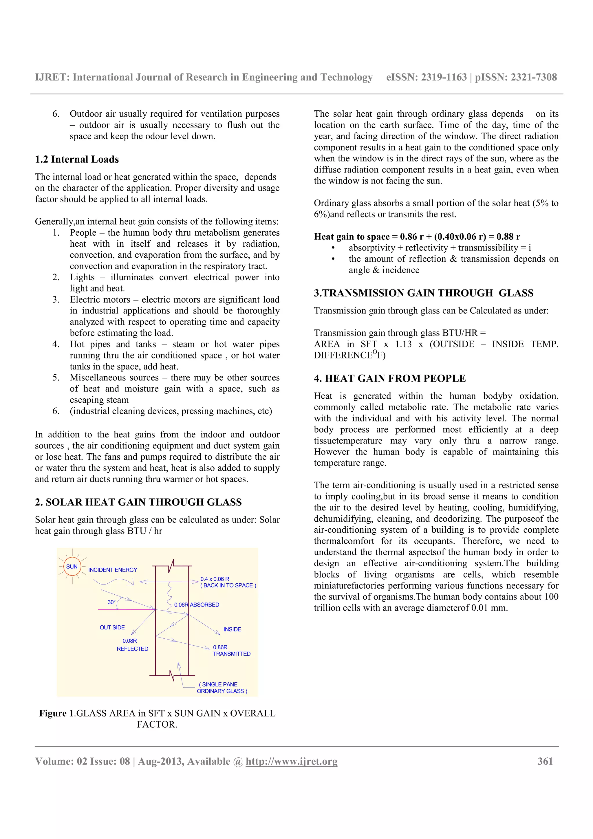
General Arrangement of AHU 2 (30000 cfm)
10. RESULT:
1. Air balancing is done measuring the velocity of air using
digital anemometer thus by arriving volume of the flow
(flow=area x velocity), regulating volume control dampers in
the ducts and controlling collar dampes provided in the air
terminal.
2. Water balancing is done as per designed flow rate using
double regulating balancing value by taking differential
pressures across the valve to ensure water flow as per the
design.
3. Temperature and relative humidity is measured is all the
conditioned area and recorded that 23 Deg C temp and 55to 58
RH, using digital temperature & RH indicator.
4. Variable air volume thermostat is set for 23Deg c and
observed that air volume is getting reduced as the VAV
actuator will close the damper proportionately on achieving set
temperature of 23c. Similarly VAV actuator opens the damper
proportionately on increase of inside the cabin temperature.
11. SCOPE OF FUTURE WORK:
Building automation system consists of Start / stop manual
auto switches along with potential free function for
monitoring the manual peration status, can be provided for
those equipment whose start stop is controlled by building
automation system.
12.REFERENCES:
[1] ASHRAE 2003 , HVAC Applications optimizing the
design and control of chilled water plants.
[2] ASHRAE Hand book
[3] Carrier Hand book
[4] System design manual by carrier.
[5] Kirsner, W. 1996. “The demise of the primary-
secondary pumping paradigm for chilled water plant
design.” Heating/Piping/ Air Conditioning
[6] Paarporn, S. “Local pumping system.” ASHRAE
[7] Avery, G. 2001. “Improving the efficiency of chilled
water plants.” ASHRAE
[8] Taylor, S. 2002. “Degrading chilled water plant delta-T:
causes and mitigation.” ASHRAE Transactions,.
[9] ASHRAE. 2002. Optimizing the Design & Control of
Chilled Water Plants,](https://image.slidesharecdn.com/designofairconditioningandventilationsystemfora-140804003951-phpapp01/75/Design-of-air-conditioning-and-ventilation-system-for-a-5-2048.jpg)

This document presents the design of a centralized air conditioning and mechanical ventilation system for a multi-storey office building in Hyderabad, covering aspects like estimated cooling load, equipment selection, and energy efficiency. The design aims to provide a thermally controlled environment across seven floors and two basements, with an emphasis on cost-effectiveness and operational flexibility. Key components include air-cooled chillers, variable air volume systems, and detailed considerations for solar heat gain and internal load management.