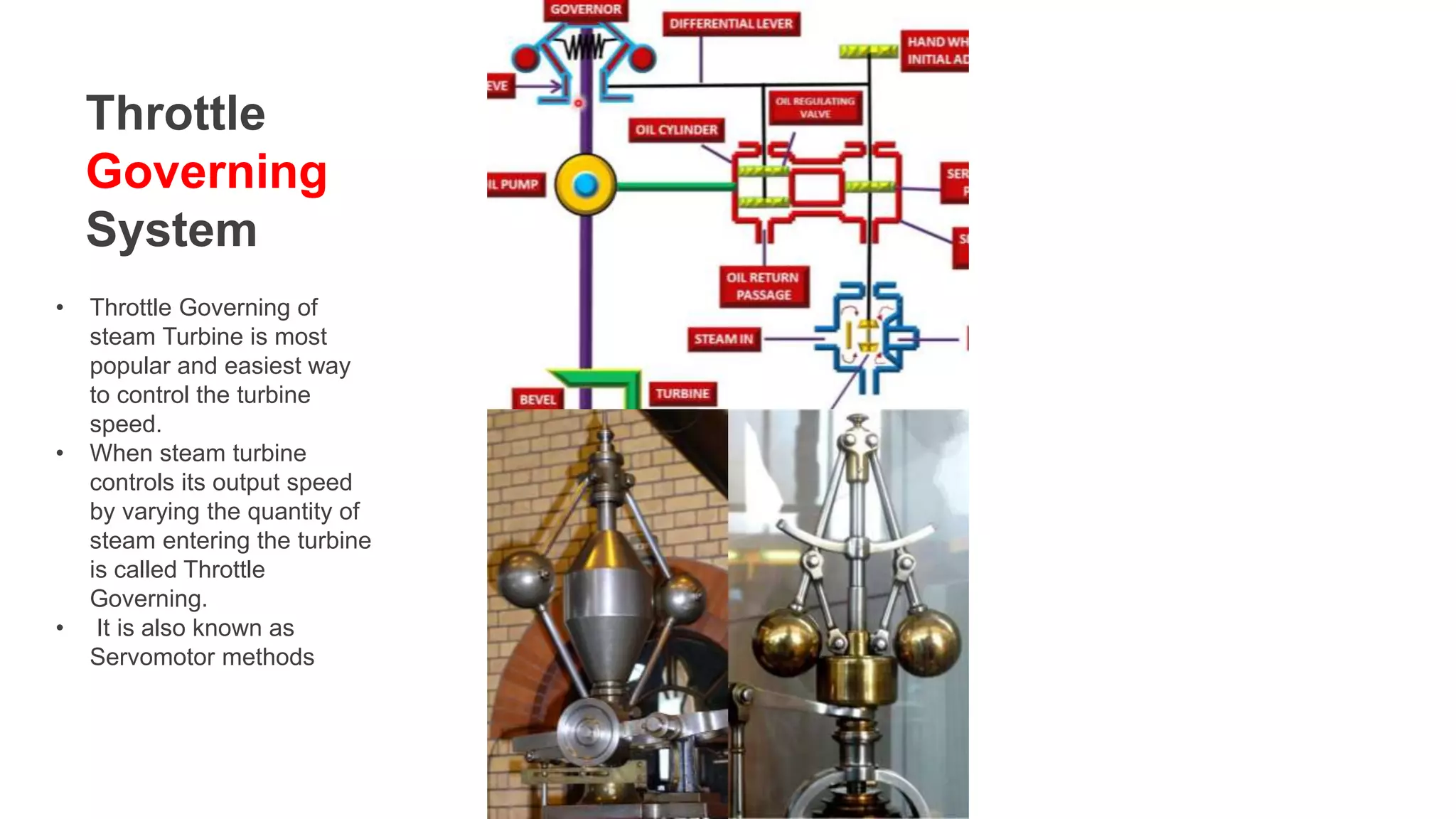
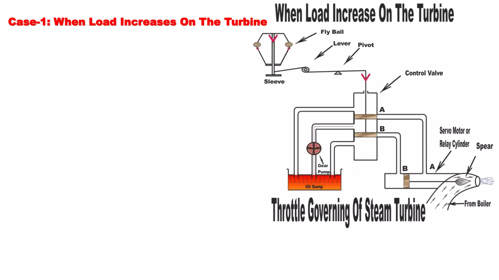
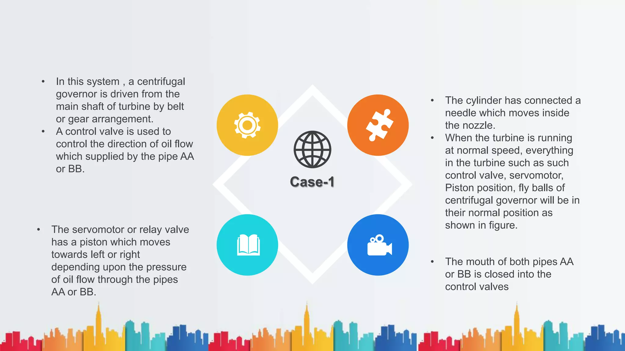
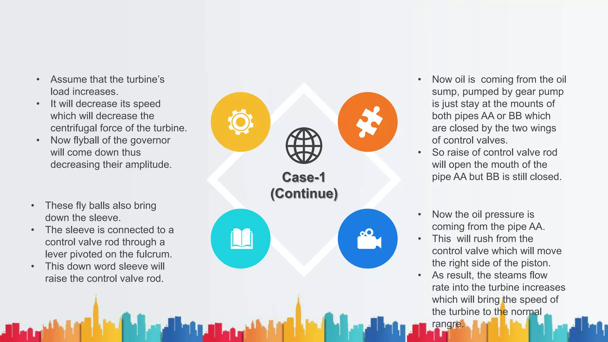
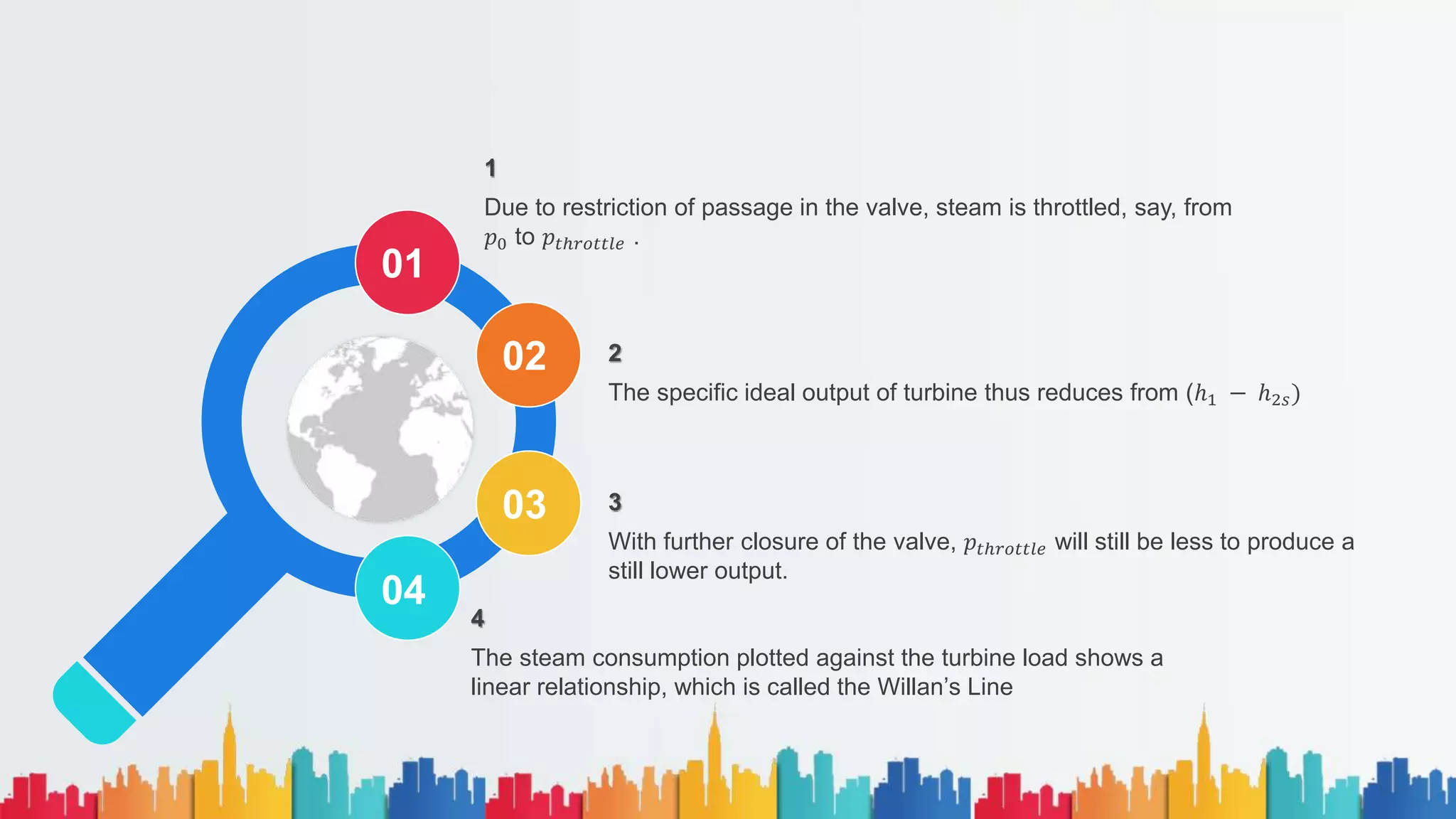
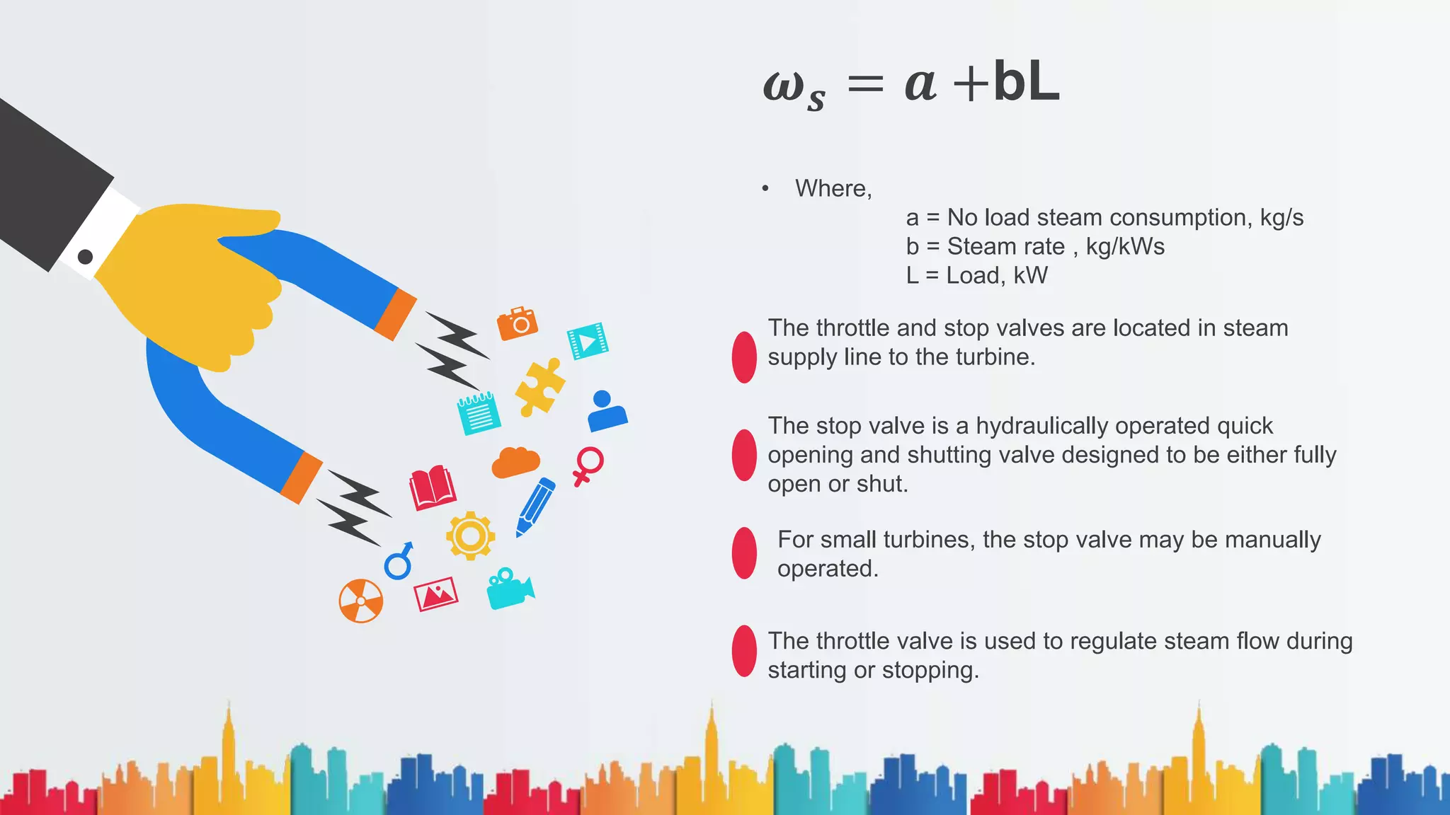
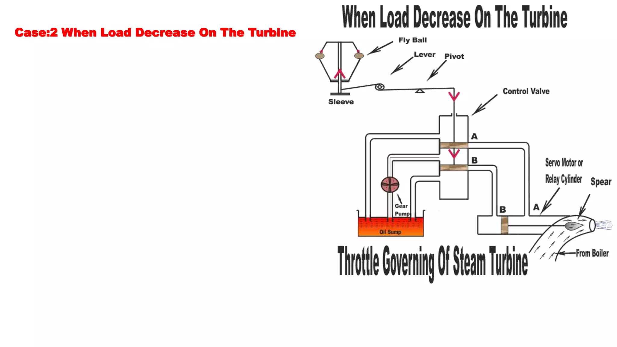
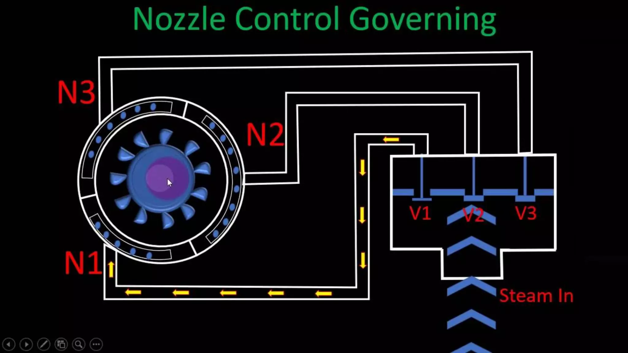
Shroff S R Rotary Institute Of Chemical
Technology, Vatariya
Subject: Power Plant Engineering (2171910)
Topic: Throttle and Nozzle governing of steam turbine
Subject Team
Dr. Hemant Gupta
Head Of Department,
Mechanical Engineering
Mr. Ankur Solanki
Assistant Professor,
Mechanical Engineering
Dhyey Shukla
170990119016
7th Semester
Mechanical Engineering
Agenda Layout
01 Throttle Governing System For Steam Turbine
02 Nozzle Governing System For Steam Turbine
03
04
05
Throttle Governing system For Steam Turbine
Throttle
Governing
System
• Throttle Governing of
steam Turbine is most
popular and easiest way
to control the turbine
speed.
• When steam turbine
controls its output speed
by varying the quantity of
steam entering the turbine
is called Throttle
Governing.
• It is also known as
Servomotor methods
Case-1: When Load Increases On The Turbine
Case-1
• The cylinder has connected a
needle which moves inside
the nozzle.
• When the turbine is running
at normal speed, everything
in the turbine such as such
control valve, servomotor,
Piston position, fly balls of
centrifugal governor will be in
their normal position as
shown in figure.
• The mouth of both pipes AA
or BB is closed into the
control valves
• In this system , a centrifugal
governor is driven from the
main shaft of turbine by belt
or gear arrangement.
• A control valve is used to
control the direction of oil flow
which supplied by the pipe AA
or BB.
• The servomotor or relay valve
has a piston which moves
towards left or right
depending upon the pressure
of oil flow through the pipes
AA or BB.
Case-1
(Continue)
• Now oil is coming from the oil
sump, pumped by gear pump
is just stay at the mounts of
both pipes AA or BB which
are closed by the two wings
of control valves.
• So raise of control valve rod
will open the mouth of the
pipe AA but BB is still closed.
• Now the oil pressure is
coming from the pipe AA.
• This will rush from the
control valve which will move
the right side of the piston.
• As result, the steams flow
rate into the turbine increases
which will bring the speed of
the turbine to the normal
rangre.
• Assume that the turbine’s
load increases.
• It will decrease its speed
which will decrease the
centrifugal force of the turbine.
• Now flyball of the governor
will come down thus
decreasing their amplitude.
• These fly balls also bring
down the sleeve.
• The sleeve is connected to a
control valve rod through a
lever pivoted on the fulcrum.
• This down word sleeve will
raise the control valve rod.
Willan’s
Line
Throttling Of Steam
1
Due to restriction of passage in the valve, steam is throttled, say, from
𝑝0 to 𝑝𝑡ℎ𝑟𝑜𝑡𝑡𝑙𝑒 .
4
The steam consumption plotted against the turbine load shows a
linear relationship, which is called the Willan’s Line
2
The specific ideal output of turbine thus reduces from (ℎ1 − ℎ2𝑠)
3
With further closure of the valve, 𝑝𝑡ℎ𝑟𝑜𝑡𝑡𝑙𝑒 will still be less to produce a
still lower output.
01
02
03
04
𝝎𝒔 = 𝒂 +bL
• Where,
a = No load steam consumption, kg/s
b = Steam rate , kg/kWs
L = Load, kW
The throttle and stop valves are located in steam
supply line to the turbine.
The stop valve is a hydraulically operated quick
opening and shutting valve designed to be either fully
open or shut.
For small turbines, the stop valve may be manually
operated.
The throttle valve is used to regulate steam flow during
starting or stopping.
Case:2 When Load Decrease On The Turbine
Nozzle Governing system For Steam Turbine
• From this method turbine speed is
controlled.
• Nozzle control governing of steam
turbine is basically used for part load
condition.
• Somme set of nozzle are grouped
together and each group of nozzle is
supplied steam controlled by valves.
• Every valve is closed by the
corresponding set of nozzle.
• Steam flow rate is also controlled by
these nozzles.
• Actually , nozzle control governing is
restricted to the first stage of turbine
whereas the subsequent nozzle are in
other stage remains constant
• According to the load demand , some
nozzles are in active and other inactive
position.
• Suppose turbine holds ten number of
nozzles.
• If the load demand is reduced by 50%
then five numbers of nozzles are in
open condition and rest is closed.
• This method is suitable for Simple
impulse Turbine.
Thank you
Questions And Suggestions Are Accepted

170990119016 dhyey shukla ppe

  • 1.
    Shroff S RRotary Institute Of Chemical Technology, Vatariya Subject: Power Plant Engineering (2171910) Topic: Throttle and Nozzle governing of steam turbine
  • 2.
    Subject Team Dr. HemantGupta Head Of Department, Mechanical Engineering Mr. Ankur Solanki Assistant Professor, Mechanical Engineering Dhyey Shukla 170990119016 7th Semester Mechanical Engineering
  • 3.
    Agenda Layout 01 ThrottleGoverning System For Steam Turbine 02 Nozzle Governing System For Steam Turbine 03 04 05
  • 4.
    Throttle Governing systemFor Steam Turbine
  • 5.
    Throttle Governing System • Throttle Governingof steam Turbine is most popular and easiest way to control the turbine speed. • When steam turbine controls its output speed by varying the quantity of steam entering the turbine is called Throttle Governing. • It is also known as Servomotor methods
  • 6.
    Case-1: When LoadIncreases On The Turbine
  • 7.
    Case-1 • The cylinderhas connected a needle which moves inside the nozzle. • When the turbine is running at normal speed, everything in the turbine such as such control valve, servomotor, Piston position, fly balls of centrifugal governor will be in their normal position as shown in figure. • The mouth of both pipes AA or BB is closed into the control valves • In this system , a centrifugal governor is driven from the main shaft of turbine by belt or gear arrangement. • A control valve is used to control the direction of oil flow which supplied by the pipe AA or BB. • The servomotor or relay valve has a piston which moves towards left or right depending upon the pressure of oil flow through the pipes AA or BB.
  • 8.
    Case-1 (Continue) • Now oilis coming from the oil sump, pumped by gear pump is just stay at the mounts of both pipes AA or BB which are closed by the two wings of control valves. • So raise of control valve rod will open the mouth of the pipe AA but BB is still closed. • Now the oil pressure is coming from the pipe AA. • This will rush from the control valve which will move the right side of the piston. • As result, the steams flow rate into the turbine increases which will bring the speed of the turbine to the normal rangre. • Assume that the turbine’s load increases. • It will decrease its speed which will decrease the centrifugal force of the turbine. • Now flyball of the governor will come down thus decreasing their amplitude. • These fly balls also bring down the sleeve. • The sleeve is connected to a control valve rod through a lever pivoted on the fulcrum. • This down word sleeve will raise the control valve rod.
  • 9.
  • 10.
    1 Due to restrictionof passage in the valve, steam is throttled, say, from 𝑝0 to 𝑝𝑡ℎ𝑟𝑜𝑡𝑡𝑙𝑒 . 4 The steam consumption plotted against the turbine load shows a linear relationship, which is called the Willan’s Line 2 The specific ideal output of turbine thus reduces from (ℎ1 − ℎ2𝑠) 3 With further closure of the valve, 𝑝𝑡ℎ𝑟𝑜𝑡𝑡𝑙𝑒 will still be less to produce a still lower output. 01 02 03 04
  • 11.
    𝝎𝒔 = 𝒂+bL • Where, a = No load steam consumption, kg/s b = Steam rate , kg/kWs L = Load, kW The throttle and stop valves are located in steam supply line to the turbine. The stop valve is a hydraulically operated quick opening and shutting valve designed to be either fully open or shut. For small turbines, the stop valve may be manually operated. The throttle valve is used to regulate steam flow during starting or stopping.
  • 12.
    Case:2 When LoadDecrease On The Turbine
  • 13.
    Nozzle Governing systemFor Steam Turbine
  • 14.
    • From thismethod turbine speed is controlled. • Nozzle control governing of steam turbine is basically used for part load condition. • Somme set of nozzle are grouped together and each group of nozzle is supplied steam controlled by valves. • Every valve is closed by the corresponding set of nozzle. • Steam flow rate is also controlled by these nozzles. • Actually , nozzle control governing is restricted to the first stage of turbine whereas the subsequent nozzle are in other stage remains constant • According to the load demand , some nozzles are in active and other inactive position. • Suppose turbine holds ten number of nozzles. • If the load demand is reduced by 50% then five numbers of nozzles are in open condition and rest is closed. • This method is suitable for Simple impulse Turbine.
  • 16.
    Thank you Questions AndSuggestions Are Accepted