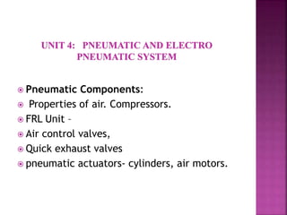
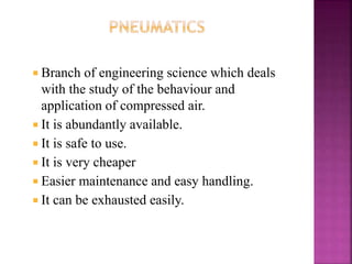
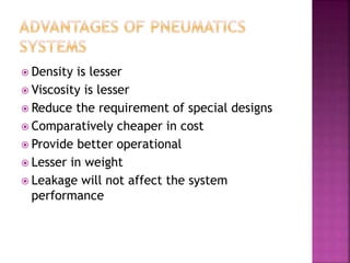
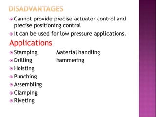
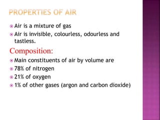
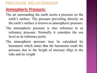
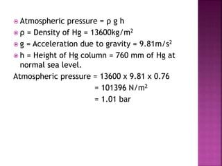
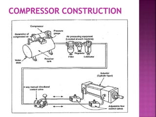
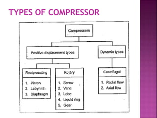
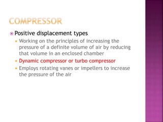
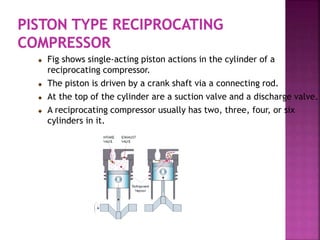
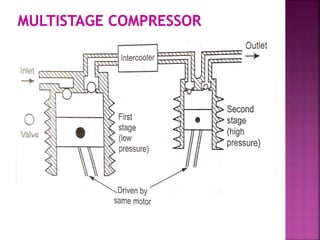
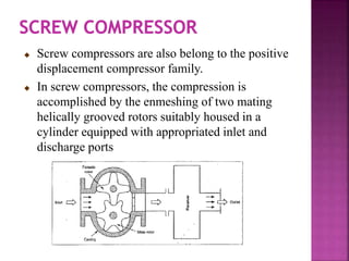
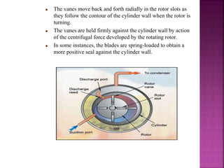
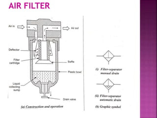
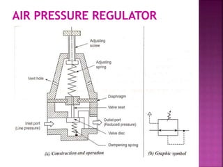
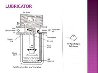
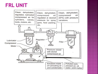
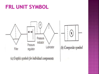
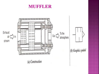
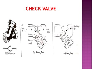
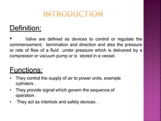
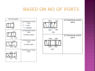
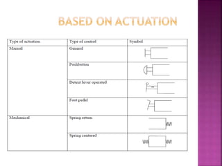
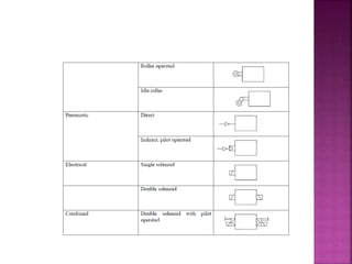
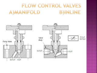
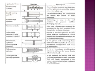
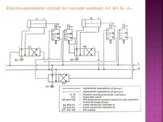
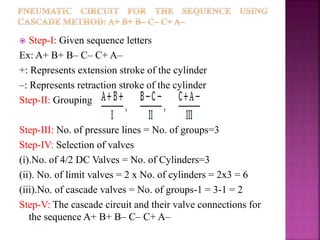
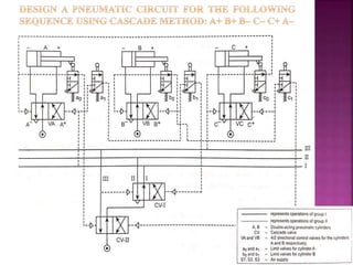
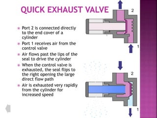
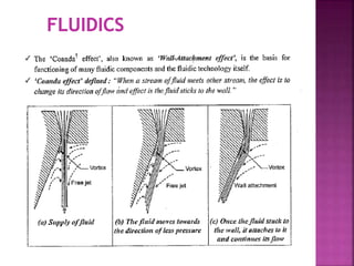
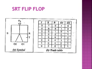
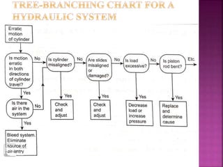
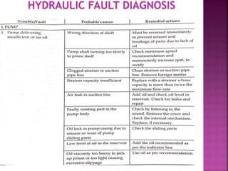
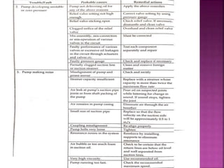
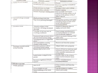
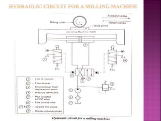
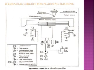
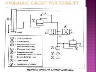
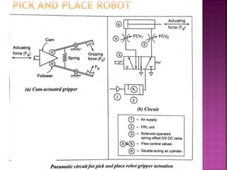
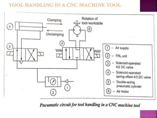
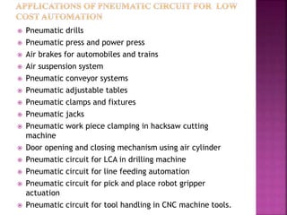
This document discusses pneumatic components and systems. It describes properties of air and compressors used to generate compressed air. It discusses the function of fluid, regulator, and lubricator (FRL) units and common pneumatic components like air control valves, quick exhaust valves, cylinders, and air motors. Applications of pneumatic systems are also listed, such as material handling, drilling, punching, and assembly operations.
Control of a single-acting and double-acting cylinder, regeneration, motor braking, speed control, synchronisation, fail safe, two handed, application of counterbalance, sequence, unloading, pressure reducing, pilot operated check valve
The pressure energy is fed to the actuator through a number of control block called valves.
• Various type of valve are used in hydraulic system to control or regulate the flow medium.
• Basicallyvalvesareexpectedtocontrol: – Direction
– Pressure
– Flow
– Otherspecialfunctions.
In hydraulic and pneumatic systems flow control valves are necessary to vary the speed of actuator. Flow control valves are placed in between Actuator and Direction Control (DC) Valve
Hydraulic Valves and Hydraulic System AccessoriesRAHUL THAKER
Hydraulic Valves and Hydraulic System Accessories:
Direction control valves,Pressure control valves, Flow control valves, Non-return valves, Reservoirs,Accumulators, Heating & cooling devices, Hoses. Selection of valves for circuits.
HYDRAULIC POWER GENERATING AND UTILIZING SYSTEMS
Introduction to fluid power system - Hydraulic fluids - functions, types, properties, selection and application.
POWER GENERATING ELEMENTS: Pumps, classification, working of different pumps such as Gear, Vane, Piston (axial and radial), pump performance or characteristics, pump selection factors- simple Problems.
POWER UTILIZING ELEMENTS: Fluid Power Actuators: Linear hydraulic actuators – Types and construction of hydraulic cylinders – Single acting, Double acting, special cylinders like tandem, Rodless, Telescopic, Cushioning mechanism.
Hydraulic Motors, types – Gear, Vane, Piston (axial and radial) – performance of motors.
Introduction to Pneumatic Systems:
Basic Requirements for Pneumatic System,Applications, Pneumatic fundamentals, Construction, working principle and operation of pneumatic power transmission system components like Power source, FRL unit, Actuators and control valves like DCV, FCV, PCV, time delay, quick exhaust, twin pressure, shuttle
This document consists of information regarding the concepts of a complete Pneumatic System and its different elements which are:-
a. Pneumatic Power Generating Elements - Pumps & Air Compressors
b. Pneumatic Power Controlling Elements - Valves
c. Pneumatic Power Utilising Elements - Cylinders
d. Pneumatic Power Conveying Elements - Hoses, Pipes, and Fittings
e. Pneumatic Accessories - Air Receiver Tank, Air Dryer, and FRL unit
with proper working and diagrams which also includes the Pneumatic circuit diagram used in industries.
Immunizing Image Classifiers Against Localized Adversary Attacksgerogepatton
This paper addresses the vulnerability of deep learning models, particularly convolutional neural networks
(CNN)s, to adversarial attacks and presents a proactive training technique designed to counter them. We
introduce a novel volumization algorithm, which transforms 2D images into 3D volumetric representations.
When combined with 3D convolution and deep curriculum learning optimization (CLO), itsignificantly improves
the immunity of models against localized universal attacks by up to 40%. We evaluate our proposed approach
using contemporary CNN architectures and the modified Canadian Institute for Advanced Research (CIFAR-10
and CIFAR-100) and ImageNet Large Scale Visual Recognition Challenge (ILSVRC12) datasets, showcasing
accuracy improvements over previous techniques. The results indicate that the combination of the volumetric
input and curriculum learning holds significant promise for mitigating adversarial attacks without necessitating
adversary training.
Industrial Training at Shahjalal Fertilizer Company Limited (SFCL)MdTanvirMahtab2
This presentation is about the working procedure of Shahjalal Fertilizer Company Limited (SFCL). A Govt. owned Company of Bangladesh Chemical Industries Corporation under Ministry of Industries.
Overview of the fundamental roles in Hydropower generation and the components involved in wider Electrical Engineering.
This paper presents the design and construction of hydroelectric dams from the hydrologist’s survey of the valley before construction, all aspects and involved disciplines, fluid dynamics, structural engineering, generation and mains frequency regulation to the very transmission of power through the network in the United Kingdom.
Author: Robbie Edward Sayers
Collaborators and co editors: Charlie Sims and Connor Healey.
(C) 2024 Robbie E. Sayers
Water scarcity is the lack of fresh water resources to meet the standard water demand. There are two type of water scarcity. One is physical. The other is economic water scarcity.
COLLEGE BUS MANAGEMENT SYSTEM PROJECT REPORT.pdfKamal Acharya
The College Bus Management system is completely developed by Visual Basic .NET Version. The application is connect with most secured database language MS SQL Server. The application is develop by using best combination of front-end and back-end languages. The application is totally design like flat user interface. This flat user interface is more attractive user interface in 2017. The application is gives more important to the system functionality. The application is to manage the student’s details, driver’s details, bus details, bus route details, bus fees details and more. The application has only one unit for admin. The admin can manage the entire application. The admin can login into the application by using username and password of the admin. The application is develop for big and small colleges. It is more user friendly for non-computer person. Even they can easily learn how to manage the application within hours. The application is more secure by the admin. The system will give an effective output for the VB.Net and SQL Server given as input to the system. The compiled java program given as input to the system, after scanning the program will generate different reports. The application generates the report for users. The admin can view and download the report of the data. The application deliver the excel format reports. Because, excel formatted reports is very easy to understand the income and expense of the college bus. This application is mainly develop for windows operating system users. In 2017, 73% of people enterprises are using windows operating system. So the application will easily install for all the windows operating system users. The application-developed size is very low. The application consumes very low space in disk. Therefore, the user can allocate very minimum local disk space for this application.
Explore the innovative world of trenchless pipe repair with our comprehensive guide, "The Benefits and Techniques of Trenchless Pipe Repair." This document delves into the modern methods of repairing underground pipes without the need for extensive excavation, highlighting the numerous advantages and the latest techniques used in the industry.
Learn about the cost savings, reduced environmental impact, and minimal disruption associated with trenchless technology. Discover detailed explanations of popular techniques such as pipe bursting, cured-in-place pipe (CIPP) lining, and directional drilling. Understand how these methods can be applied to various types of infrastructure, from residential plumbing to large-scale municipal systems.
Ideal for homeowners, contractors, engineers, and anyone interested in modern plumbing solutions, this guide provides valuable insights into why trenchless pipe repair is becoming the preferred choice for pipe rehabilitation. Stay informed about the latest advancements and best practices in the field.
Hybrid optimization of pumped hydro system and solar- Engr. Abdul-Azeez.pdffxintegritypublishin
Advancements in technology unveil a myriad of electrical and electronic breakthroughs geared towards efficiently harnessing limited resources to meet human energy demands. The optimization of hybrid solar PV panels and pumped hydro energy supply systems plays a pivotal role in utilizing natural resources effectively. This initiative not only benefits humanity but also fosters environmental sustainability. The study investigated the design optimization of these hybrid systems, focusing on understanding solar radiation patterns, identifying geographical influences on solar radiation, formulating a mathematical model for system optimization, and determining the optimal configuration of PV panels and pumped hydro storage. Through a comparative analysis approach and eight weeks of data collection, the study addressed key research questions related to solar radiation patterns and optimal system design. The findings highlighted regions with heightened solar radiation levels, showcasing substantial potential for power generation and emphasizing the system's efficiency. Optimizing system design significantly boosted power generation, promoted renewable energy utilization, and enhanced energy storage capacity. The study underscored the benefits of optimizing hybrid solar PV panels and pumped hydro energy supply systems for sustainable energy usage. Optimizing the design of solar PV panels and pumped hydro energy supply systems as examined across diverse climatic conditions in a developing country, not only enhances power generation but also improves the integration of renewable energy sources and boosts energy storage capacities, particularly beneficial for less economically prosperous regions. Additionally, the study provides valuable insights for advancing energy research in economically viable areas. Recommendations included conducting site-specific assessments, utilizing advanced modeling tools, implementing regular maintenance protocols, and enhancing communication among system components.
Forklift Classes Overview by Intella PartsIntella Parts
Discover the different forklift classes and their specific applications. Learn how to choose the right forklift for your needs to ensure safety, efficiency, and compliance in your operations.
For more technical information, visit our website https://intellaparts.com
AKS UNIVERSITY Satna Final Year Project By OM Hardaha.pdf
HP UNIT 4 PPT
1.
2. Pneumatic Components:
Properties of air. Compressors.
FRL Unit –
Air control valves,
Quick exhaust valves
pneumatic actuators- cylinders, air motors.
3. Branch of engineering science which deals
with the study of the behaviour and
application of compressed air.
It is abundantly available.
It is safe to use.
It is very cheaper
Easier maintenance and easy handling.
It can be exhausted easily.
4. Density is lesser
Viscosity is lesser
Reduce the requirement of special designs
Comparatively cheaper in cost
Provide better operational
Lesser in weight
Leakage will not affect the system
performance
5. Cannot provide precise actuator control and
precise positioning control
It can be used for low pressure applications.
Applications
Stamping Material handling
Drilling hammering
Hoisting
Punching
Assembling
Clamping
Riveting
6. Air is a mixture of gas
Air is invisible, colourless, odourless and
tastless.
Composition:
Main constituents of air by volume are
78% of nitrogen
21% of oxygen
1% of other gases (argon and carbon dioxide)
7. Atmospheric Pressure:
The air surrounding the earth exerts a pressure on the
earth’s surface. The pressure prevailing directly on
the earth’s surface is known as atmospheric pressure.
The atmospheric pressure is also reference to as
reference pressure. Normally it considers the sea
level as its reference point.
The atmospheric pressure may be calculated by
barometer which states that the barometer reads the
pressure due to the height of mercury (Hg) in the
tube and its weight
8. Atmospheric pressure = ρ g h
ρ = Density of Hg = 13600kg/m2
g = Acceleration due to gravity = 9.81m/s2
h = Height of Hg column = 760 mm of Hg at
normal sea level.
Atmospheric pressure = 13600 x 9.81 x 0.76
= 101396 N/m2
= 1.01 bar
9.
10. Pressure and Volume: Boyle’s Law
How is the pressure applied to a gas related to its volume?
Piston
Gas molecules
Piston
Gas molecules
Volume is inversely proportional to applied pressure.
Boyle’s Law: P1V1 = P2V2
11. How is the volume of a gas related to its temperature?
moveable mass (constant pressure)
gas molecules
The volume of a gas is directly
proportional to its Temperature
(temperature must be in Kelvin)
Charles’s Law: V1/T1 = V2/T2
12. 1. Volume held CONSTANT
2. Found direct relationship
between temperature & pressure
3. P1 = P2
T1 T2
13. Combined Gas Law (Boyle and Charles):
T must be in Kelvin
Can be rearranged to:
P1V1T2 = P2V2T1
A combined gas law problem can be recognized by
having two sets of conditions.
Note: if one set of parameters is unchanged that term
will cancel on each side.
14. 1. Contains ALL variables
2. P V = n R T
3. Where
P = pressure (depends on R)
V = volume (liters)
n = amount of gas (moles)
R = ideal gas constant (depends on
pressure) T = temperature (Kelvin)
15.
16.
17. Positive displacement types
Working on the principles of increasing the
pressure of a definite volume of air by reducing
that volume in an enclosed chamber
Dynamic compressor or turbo compressor
Employs rotating vanes or impellers to increase
the pressure of the air
18. Fig shows single-acting piston actions in the cylinder of a
reciprocating compressor.
The piston is driven by a crank shaft via a connecting rod.
At the top of the cylinder are a suction valve and a discharge valve.
A reciprocating compressor usually has two, three, four, or six
cylinders in it.
19. Staging
Dividing the total pressure among two or more
cylinders by allowing the outlet from one
cylinder into the inlet of the next cylinder and so
on.
In single stage compressor gives the compressed
air of about 5 bar, the compressed air
temperature can rise over to 200⁰C.
effective cooling of compressor is necessary.
When used multistage compressor effective cooling
can be implemented between stages.
Reduces input power requirements
Increase the efficiency of the compressor.
20. Pressure has been developed in the
compressor piping. The pressure will push
back against the compressor. This makes
starting the compressor more difficult when
required.
Starting unloader valve is required to start
compressor whenever desired .This
arrangement releases the pressure in the
piping to the atmosphere and now the
compressor is free to start.
21.
22. Screw compressors are also belong to the positive
displacement compressor family.
In screw compressors, the compression is
accomplished by the enmeshing of two mating
helically grooved rotors suitably housed in a
cylinder equipped with appropriated inlet and
discharge ports
23. The rotor shaft is mounted eccentrically in a
steel cylinder so that the rotor nearly touches
the cylinder wall on one side, the two being
separated only by an oil film at this point.
Directly opposite this point the clearance
between the rotor and the cylinder wall is
maximum.
Heads or end-plates are installed on the ends
of the cylinder and to hold the rotor shaft.
24. The vanes move back and forth radially in the rotor slots as
they follow the contour of the cylinder wall when the rotor is
turning.
The vanes are held firmly against the cylinder wall by action
of the centrifugal force developed by the rotating rotor.
In some instances, the blades are spring-loaded to obtain a
more positive seal against the cylinder wall.
25.
26.
27.
28.
29.
30.
31.
32.
33.
34. Definition:
• Valve are defined as devices to control or regulate the
commencement, termination and direction and also the pressure
or rate of flow of a fluid under pressure which is delivered by a
compressor or vacuum pump or is stored in a vessel.
Functions:
• They control the supply of air to power units, example
cylinders .
• They provide signal which govern the sequence of
operation .
• They act as interlock and safety devices .
36. • Directional valves control the way the air passes
and are used principally for controlling
commencement, termination and direction of air
flow. The different classification scheme of the
pneumatic cylinders are given below
1. Based on construction
• i) Poppet or seat valves
- Ball seat valve
- Disc seat valve
- Diaphragm Valves
37. • 2. Based on the Number of ports
I. Two way valves
II. Three way valves
III.Four way valves
• 3. Based on methods of actuation
I. Manual
II. Mechanical
III.
IV.
V.
Electrical
Pneumatic
Combined action
• 4. Based on mounting styles
I. Manifold
II. In-line
38.
39.
40.
41.
42.
43.
44.
45. • Pressure control valves control the
pressure of the air flowing through the
valve or confined in the system controlled
by the valve.
There are three types of pressure control
valves
1. Pressure limiting valve
2. Pressure regulator or pressure reducing
valve
46.
47.
48.
49.
50.
51.
52.
53.
54.
55.
56. For sequencing operations, the pneumatic
circuits can be designed in various methods
follows:
Classic method
Cascade method
Step-counter method
Logic design method
Combinational circuit design
57.
58. Step-I: Given sequence letters
Ex: A+ B+ B– A– C+ C–
+: Represents extension stroke of the cylinder
–: Represents retraction stroke of the cylinder
Step-II: Grouping
Group minimal, C– can be assigned to group I
Step-III: No. of pressure lines = No. of groups=2
Step-IV: Selection of valves
(i).No. of 4/2 DC Valves = No. of Cylinders=2
(ii). No. of limit valves = 2 x No. of cylinders = 2x2 = 4
(iii).No. of cascade valves = No. of groups-1 = 2-1 = 1
Step-IV: The cascade circuit and their valve connections for the
sequence A+ B+ B– A– C+ C–
59.
60.
61. Step-I: Given sequence letters
Ex: A+ B+ B– A–
+: Represents extension stroke of the cylinder
–: Represents retraction stroke of the cylinder
Step-II: Grouping
Step-III: No. of pressure lines = No. of groups=2
Step-IV: Selection of valves
(i).No. of 4/2 DC Valves = No. of Cylinders=2
(ii). No. of limit valves = 2 x No. of cylinders = 2x2 = 4
(iii).No. of cascade valves = No. of groups-1 = 2-1 = 1
Step-IV: The cascade circuit and their valve connections for
the sequence A+ B+ B– A–
62.
63.
64. Step-I: Given sequence letters
Ex: A+ B+ B– C– C+ A–
+: Represents extension stroke of the cylinder
–: Represents retraction stroke of the cylinder
Step-II: Grouping
Step-III: No. of pressure lines = No. of groups=3
Step-IV: Selection of valves
(i).No. of 4/2 DC Valves = No. of Cylinders=3
(ii). No. of limit valves = 2 x No. of cylinders = 2x3 = 6
(iii).No. of cascade valves = No. of groups-1 = 3-1 = 2
Step-V: The cascade circuit and their valve connections for
the sequence A+ B+ B– C– C+ A–
65.
66. Port 2 is connected directly
to the end cover of a
cylinder
Port 1 receives air from the
control valve
Air flows past the lips of the
seal to drive the cylinder
When the control valve is
exhausted, the seal flips to
the right opening the large
direct flow path
Air is exhausted very rapidly
from the cylinder for
increased speed
1
2
1
2
1
2
67. Fluidics – Introduction to fluidic devices,
simple circuits Introduction to Electro
Hydraulic Pneumatic logic circuits, PLC
applications in fluid power control, ladder
diagrams
Fluid Power Circuit Design: Sequential circuit
design for simple applications using classic,
cascade, step counter, logic with Karnaugh-
Veitch Mapping and combinational circuit
design methods.
68.
69.
70.
71.
72.
73.
74.
75.
76.
77.
78. Reduced speed of travel of machine tool
elements.
Slow response to control.
Excessive leakage in the system.
Excessive loss of system pressure.
Rise in the oil temperature.
Non-uniform or jerky movement of tables,
carriages at low feed rate.
Increased noise in the system.
No supply or less supply from pump.
Cavitation of seal failure.
Poor oil life
79. Inadequate supply of oil in the reservoir.
Clogged or dirty oil filters.
Leaking seals.
Loose inlet lines the cause the pump to take
in air.
Incorrect type of oil.
Excessive oil temperature.
Excessive oil pressure.
80.
81.
82.
83.
84.
85.
86.
87.
88.
89.
90.
91.
92.
93.
94.
95.
96.
97.
98.
99.
100.
101.
102.
103. Quality improvement and repeatability in
quality.
Cost reduction.
Improved sustainability.
Improved safety.
Reduced rejection
104. Low cost automation is defined as a technology
that creates some degree of automation around the
existing equipment, tools, methods and people,
using mostly standard components available in the
market.
Low Cost Automation main used:
To reduce machine investment cost.
To reduce the process time.
To increase productivity.
To have consistent quality.
105. Material movement/ handling operations.
Loading
Feeding
Pick and place functions
Clamping
Welding
Forming
Machining operations like drilling, riveting, broaching,
shaping etc.
Painting
Measurement and inspection functions such as
marking, checking, gauging etc.
Assembly and packing
106. Using gravitational force
Using leverage systems
Using hydraulic systems
Using pneumatic systems
Using electromagnetic systems
107. Hydraulic circuit for a drilling machine
Hydraulic circuit for a shaping machine
Hydraulic circuit for a planning machine
Hydraulic circuit for a surface grinding machine
Hydraulic circuit for a milling machine
Hydraulic circuit for a punching machine
Hydraulic circuit for a forging machine
Hydraulic circuit for a forklift machine
Hydraulic circuit for a drilling machine
Hydraulic power steering
Hydraulic braking for automobiles
Hydraulic circuit used in construction,
agricultural, mining industries.
108. Pneumatic drills
Pneumatic press and power press
Air brakes for automobiles and trains
Air suspension system
Pneumatic conveyor systems
Pneumatic adjustable tables
Pneumatic clamps and fixtures
Pneumatic jacks
Pneumatic work piece clamping in hacksaw cutting
machine
Door opening and closing mechanism using air cylinder
Pneumatic circuit for LCA in drilling machine
Pneumatic circuit for line feeding automation
Pneumatic circuit for pick and place robot gripper
actuation
Pneumatic circuit for tool handling in CNC machine tools.
109. A hydraulic power pack is a self contained unit that is used
instead of a built in power supply for hydraulic machinery.
It works to apply the hydraulic pressure needed to drive
motors, cylinders and other complementary parts of given
hydraulic system.
The hydraulic power pack is also called as hydraulic power
unit.
110. A hydraulic reservoir (or) tank
Regulator
Pressure supply lines and pressure relief line
Electrical motor
Pump
Other components:
(i). Filters
(ii). Pressure control valves
(iii).Directional control valves
(iv). Flow control valves
(v). Accumulators
(vi). Coolers and heaters
(vii). Power unit controllers
111. A pneumatic power pack is self contained unit that is used
instead of a built in power supply for pneumatic machinery.
It work apply the air pressure needed to drive motors,
cylinders, and other complementary parts of a given
pneumatic system.
The pneumatic power pack is also called as pneumatic
power unit.
112. Electric motor
Compressor
reservoir
Air cooler
Air dryer/separator
Valves (flow, pressure and DC valves)
FRL unit