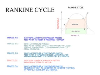
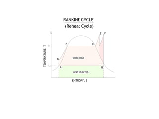
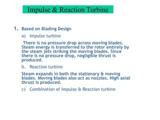
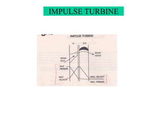
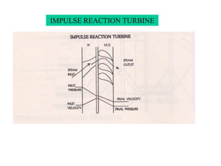
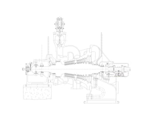
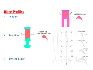
What is a Turbine ?
-A Turbine is a device which converts the heat energy of
steam into the kinetic energy & then to rotational energy.
-The Motive Power in a steam turbine is obtained by the
rate of change in momentum of a high velocity jet of
steam impinging on a curved blade which is free to
rotate.
-The basic cycle for the steam turbine power plant is the
Rankine cycle. The modern Power plant uses the rankine
cycle modified to include superheating, regenerative feed
water heating & reheating.
PROCESS A-B: ISENTROPIC/ADIABATIC COMPRESSION PROCESS
FEED WATER TO BOILER IS PRESSURIED TO BOILER
FEED WATER HEATED UPTO SATURATION TEMP T1 CALLED
CONSTANT PRESSURE PROCESS
PROCESS B-C:
SENSIBLE HEATING POINT C IS INTERMEDIATE POINT OF
VAPOURISATION POINT D IS STEAM IS DRY & SATURATED.
FEED WATER IS VAPOURISED CALLED LANTENT HEAT OF
CONSTANT PRESSURE & TEMPERATURE PROCESS
PROCESS C-D:
ISENTROPIC/ADIABATIC EXPANSION PROCESS
EXPANSION OF STEAM TO VACCUM
PROCESS D-E:
AT POINT D, STEAM IS DRY & SATURATED.
REJECTION OF HEAT TO CONDENSOR TO CONDENSE THE STEAM.
CONSTANT PRESSURE & TEMPERATURE PROCESS
PROCESS E-A:
STEAM GENERATION
A
B
C D
E
D'
E'
WORK DONE
HEAT REJECTED
ENTROPY, S
TEMPERATURE,
T
RANKINE CYCLE
RANKINE CYCLE
HEAT REJECTED
TEMPERATURE,
T
A
B WORK DONE
C
G
D
F
RANKINE CYCLE
(Reheat Cycle)
E
ENTROPY, S
Impulse & Reaction Turbine
1. Based on Blading Design
a) Impulse turbine
There is no pressure drop across moving blades.
Steam energy is transferred to the rotor entirely by
the steam jets striking the moving blades. Since
there is no pressure drop, negligible thrust is
produced.
b. Reaction turbine
Steam expands in both the stationary & moving
blades. Moving blades also act as nozzles. High axial
thrust is produced.
c) Combination of Impulse & Reaction turbine
IMPULSE TURBINE
a
IMPULSE REACTION TURBINE
DIFFERENCES
Impulse & Reaction Turbine
Impulse Reaction
-Pressure drops in nozzles and not in moving blade -Pressure drops in fixed blade as
well as in moving blades
-Constant blade channel area -Varying blade channel area
-Profile type blades -Aerofoil type blades
-Restricted round or incomplete admission of steam -All round or complete admission
-Diaphragm contains nozzles -Fixed blades similar to moving blades attached to
casing serve as nozzles and
guide the steam
-Occupies less space for same power -Occupies more space for same power
-Higher efficiency in initial stage - higher efficiency in final stages.
-Suitable for small power requirements -Suitable for medium or high power requirements.
-Blade manufacturing is not difficult -Blade manufacturing process is difficult.
-Velocity of steam is high -Velocity of steam is less.
On the Principle of working
1. Impulse Turbine
2. Reaction Turbine
Turbines Classification
Based on Inlet & Outlet Steam Condition
• Back pressure turbines – The Exhaust steam from
the turbine flows out of the steam piping at medium or low
pressure. Basically, the exhaust steam can be used effectively
in any other machines or equipment in the plant.
• Condensing turbines – Full steam quantities
entering into the turbine are exhausted, and converted to
condensate in a condenser. The exhaust steam pressure is
lower than the atmospheric pressure.
• Extraction turbines – Medium or low pressure steam
required by the process plant is extracted from the
intermediate stage of a condensing or back pressure turbine.
CONSTRUCTIONAL FEATURES
• CASING : MADE OF CAST STEEL EXCEPT CONDENSING
STAGE WHICH IS MADE OF CAST IRON. IT IS MOUNTED ON
THE FRONT-END BEARING PEDESTAL. EXPANSION OF
CASING IS TOWARDS FRONT END.
• ROTOR : MACHINED FROM A FORGED BLANK OF ALLOY
STEEL. ROTOR IS A SINGLE FORGING INCORPORATING THE
THRUST BEARING COLLARS. IT IS SUPPORTED ON TWO
PRESSURE LUBRICATED JOURNAL BEARINGS. EXPANSION
OF ROTOR IS TOWARDS REAR END.
• CONTROL STAGE : CONSISTS OF MOVING BLADES &
NOZZLES. NOZZLES ARE MACHINED FROM SOLID BLANKS.
THE MOVING BLADES ARE MACHINED FROM SOLID BAR
STOCK & HAVE INVERTED TEE ROOTS. TEE ROOTS ARE
INSERTED INTO GROVES IN THE TURBINE ROTOR &
CAULKED WITH BRASS STRIP.
1. External Losses
- ESV & strainer losses
- Governing losses (throttling losses)
- Leaving Energy Losses (Latent heat of exhaust steam in condenser)
- Radiation Loss to the surroundings
2. Internal Losses
a) Blade losses
i) Primary Losses:
Friction loss due to profile surface finish
ii) Secondary Losses:
- Impingement loss
LOSSES
Losses in Turbine (contd.)
b) Inter stage Tip Leakages:
Steam throttles in the inter stage seals without doing work
c) Residual velocity Losses:
Kinetic energy of the leaving steam of one stage will be carried
over to the next stage. As the axial clearances increase between
the stages (or stage groups) part of the kinetic energy will be lost.
CROSS-SECTIONAL DRAWING OF BLADED ROTOR
COUPLING
THRUST
COLLAR
H.P.BLADES
L.P
BLADES
HAND
BARRING
WHEEL
MOVING
WHEEL
FOR
OIL
TURBINE
DISCONNECT
COUPLING
INTER STAGE SEALING
Blade Profiles
• Impulse
• Reaction
• Twisted Blade
A A
(SIMPLIFIED DIAGRAM)
SECTION A-A
A B
( SIMPLIFIED DIAGRAM )
SECTION A-B
SECTION A7-A7
A
A
SECTION A3-A3
A
SECTION A13-A13
A
A
A A
SECTION A16-A16
A1
Y
A1
U
A
A4 A4
A7 A7
A10
A13 A13
A10
A18 A18
DEFINITION OF GOVERNING
SYSTEM
“A SYSTEM WHOSE PURPOSE IS TO CONTROLA PRIME
MOVER”
The function of governor is to control the speed of the
turbine.It does this by controlling the flow of steam to the
nozzles.When the governor reacts to speed, it controls the
steam flow and steam flow by defination is power.
Therefore, through speed governing shaft output speed is
governed with variable power output.
Types of Governor
1. Mechanical Governor
2. Hydraulic Governor
3. Combination of mechanical & Hydraulic
4. Pneumatic Governor
5. Electronic Governor
Protection Requirements
• Over speed
• Low Lube oil pressure
• Low vacuum
• Axial shift
• High Vibration
• Bearing temperature
• High/low extraction pressure
• Exhaust temperature
• Generator / Compressor protections
• Manual / Remote trip
EMERGENCY STOP VALVE
CYLINDER WITH TEST PISTON
TESTER-OIL
START-UP OIL
DRAIN
TRIP OIL
STOP VALVE
GOVERNING VALVE ASSEMBLY WITH ACTUATOR
HP GOVERNING
VALVE ASSEMBLY
YOKE ASSEMBLY
SERVOMOTOR
PILOT VALVE
MECHANICAL TRIPPING DEVICE
(VERTICAL MOUNTING)
MECHANICAL OVER
SPEED GOVERNOR

.steam turbine for mechanical engineering .ppt

  • 1.
    What is aTurbine ? -A Turbine is a device which converts the heat energy of steam into the kinetic energy & then to rotational energy. -The Motive Power in a steam turbine is obtained by the rate of change in momentum of a high velocity jet of steam impinging on a curved blade which is free to rotate. -The basic cycle for the steam turbine power plant is the Rankine cycle. The modern Power plant uses the rankine cycle modified to include superheating, regenerative feed water heating & reheating.
  • 2.
    PROCESS A-B: ISENTROPIC/ADIABATICCOMPRESSION PROCESS FEED WATER TO BOILER IS PRESSURIED TO BOILER FEED WATER HEATED UPTO SATURATION TEMP T1 CALLED CONSTANT PRESSURE PROCESS PROCESS B-C: SENSIBLE HEATING POINT C IS INTERMEDIATE POINT OF VAPOURISATION POINT D IS STEAM IS DRY & SATURATED. FEED WATER IS VAPOURISED CALLED LANTENT HEAT OF CONSTANT PRESSURE & TEMPERATURE PROCESS PROCESS C-D: ISENTROPIC/ADIABATIC EXPANSION PROCESS EXPANSION OF STEAM TO VACCUM PROCESS D-E: AT POINT D, STEAM IS DRY & SATURATED. REJECTION OF HEAT TO CONDENSOR TO CONDENSE THE STEAM. CONSTANT PRESSURE & TEMPERATURE PROCESS PROCESS E-A: STEAM GENERATION A B C D E D' E' WORK DONE HEAT REJECTED ENTROPY, S TEMPERATURE, T RANKINE CYCLE RANKINE CYCLE
  • 3.
    HEAT REJECTED TEMPERATURE, T A B WORKDONE C G D F RANKINE CYCLE (Reheat Cycle) E ENTROPY, S
  • 4.
    Impulse & ReactionTurbine 1. Based on Blading Design a) Impulse turbine There is no pressure drop across moving blades. Steam energy is transferred to the rotor entirely by the steam jets striking the moving blades. Since there is no pressure drop, negligible thrust is produced. b. Reaction turbine Steam expands in both the stationary & moving blades. Moving blades also act as nozzles. High axial thrust is produced. c) Combination of Impulse & Reaction turbine
  • 5.
  • 6.
  • 7.
  • 8.
    Impulse & ReactionTurbine Impulse Reaction -Pressure drops in nozzles and not in moving blade -Pressure drops in fixed blade as well as in moving blades -Constant blade channel area -Varying blade channel area -Profile type blades -Aerofoil type blades -Restricted round or incomplete admission of steam -All round or complete admission -Diaphragm contains nozzles -Fixed blades similar to moving blades attached to casing serve as nozzles and guide the steam -Occupies less space for same power -Occupies more space for same power -Higher efficiency in initial stage - higher efficiency in final stages. -Suitable for small power requirements -Suitable for medium or high power requirements. -Blade manufacturing is not difficult -Blade manufacturing process is difficult. -Velocity of steam is high -Velocity of steam is less. On the Principle of working 1. Impulse Turbine 2. Reaction Turbine
  • 9.
    Turbines Classification Based onInlet & Outlet Steam Condition • Back pressure turbines – The Exhaust steam from the turbine flows out of the steam piping at medium or low pressure. Basically, the exhaust steam can be used effectively in any other machines or equipment in the plant. • Condensing turbines – Full steam quantities entering into the turbine are exhausted, and converted to condensate in a condenser. The exhaust steam pressure is lower than the atmospheric pressure. • Extraction turbines – Medium or low pressure steam required by the process plant is extracted from the intermediate stage of a condensing or back pressure turbine.
  • 10.
    CONSTRUCTIONAL FEATURES • CASING: MADE OF CAST STEEL EXCEPT CONDENSING STAGE WHICH IS MADE OF CAST IRON. IT IS MOUNTED ON THE FRONT-END BEARING PEDESTAL. EXPANSION OF CASING IS TOWARDS FRONT END. • ROTOR : MACHINED FROM A FORGED BLANK OF ALLOY STEEL. ROTOR IS A SINGLE FORGING INCORPORATING THE THRUST BEARING COLLARS. IT IS SUPPORTED ON TWO PRESSURE LUBRICATED JOURNAL BEARINGS. EXPANSION OF ROTOR IS TOWARDS REAR END. • CONTROL STAGE : CONSISTS OF MOVING BLADES & NOZZLES. NOZZLES ARE MACHINED FROM SOLID BLANKS. THE MOVING BLADES ARE MACHINED FROM SOLID BAR STOCK & HAVE INVERTED TEE ROOTS. TEE ROOTS ARE INSERTED INTO GROVES IN THE TURBINE ROTOR & CAULKED WITH BRASS STRIP.
  • 11.
    1. External Losses -ESV & strainer losses - Governing losses (throttling losses) - Leaving Energy Losses (Latent heat of exhaust steam in condenser) - Radiation Loss to the surroundings 2. Internal Losses a) Blade losses i) Primary Losses: Friction loss due to profile surface finish ii) Secondary Losses: - Impingement loss LOSSES
  • 12.
    Losses in Turbine(contd.) b) Inter stage Tip Leakages: Steam throttles in the inter stage seals without doing work c) Residual velocity Losses: Kinetic energy of the leaving steam of one stage will be carried over to the next stage. As the axial clearances increase between the stages (or stage groups) part of the kinetic energy will be lost.
  • 15.
    CROSS-SECTIONAL DRAWING OFBLADED ROTOR COUPLING THRUST COLLAR H.P.BLADES L.P BLADES HAND BARRING WHEEL MOVING WHEEL FOR OIL TURBINE DISCONNECT COUPLING
  • 17.
  • 18.
    Blade Profiles • Impulse •Reaction • Twisted Blade A A (SIMPLIFIED DIAGRAM) SECTION A-A A B ( SIMPLIFIED DIAGRAM ) SECTION A-B SECTION A7-A7 A A SECTION A3-A3 A SECTION A13-A13 A A A A SECTION A16-A16 A1 Y A1 U A A4 A4 A7 A7 A10 A13 A13 A10 A18 A18
  • 19.
    DEFINITION OF GOVERNING SYSTEM “ASYSTEM WHOSE PURPOSE IS TO CONTROLA PRIME MOVER” The function of governor is to control the speed of the turbine.It does this by controlling the flow of steam to the nozzles.When the governor reacts to speed, it controls the steam flow and steam flow by defination is power. Therefore, through speed governing shaft output speed is governed with variable power output.
  • 20.
    Types of Governor 1.Mechanical Governor 2. Hydraulic Governor 3. Combination of mechanical & Hydraulic 4. Pneumatic Governor 5. Electronic Governor
  • 21.
    Protection Requirements • Overspeed • Low Lube oil pressure • Low vacuum • Axial shift • High Vibration • Bearing temperature • High/low extraction pressure • Exhaust temperature • Generator / Compressor protections • Manual / Remote trip
  • 22.
  • 23.
    CYLINDER WITH TESTPISTON TESTER-OIL START-UP OIL DRAIN TRIP OIL STOP VALVE
  • 24.
  • 25.
  • 26.
  • 27.
  • 28.
  • 29.
    MECHANICAL TRIPPING DEVICE (VERTICALMOUNTING) MECHANICAL OVER SPEED GOVERNOR