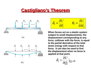
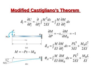
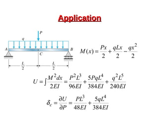
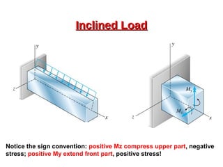
This document provides an overview of beam and column design concepts. It discusses types of beam supports, beams, shear force and bending moment diagrams, stresses in beams from bending and shear, and beam deflection calculations. It also covers column buckling, including the Euler buckling formula and Johnson's equation. The document provides examples of calculating stresses, strains, deflections, and buckling loads for different beam and column scenarios.


![Deflection [Everything’s a Spring]Deflection [Everything’s a Spring]
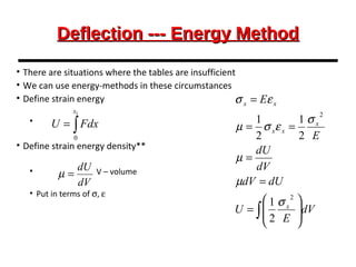
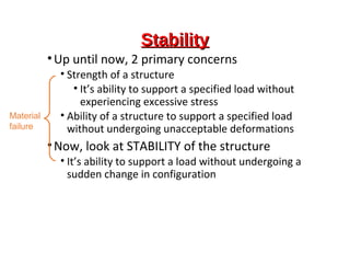
• When loads are applied, we have deflection
• Depends on
• Type of loading
• Tension
• Compression
• Bending
• Torsion
• Cross-section of member
• Comparable to pushing on a spring
• We can calculate the amount of beam deflection by
various methods](https://image.slidesharecdn.com/mdid-beamsandcolumns170990119014-16-190417110928/85/Beams-And-Columns-40-320.jpg)
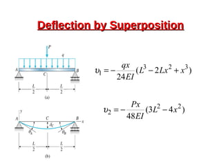
![SuperpositionSuperposition
• Determine effects of individual loads separately and
add the results [see examples 4-2,3,4]
• Tables are useful – see A-9
• May be applied if
• Each effect is linearly related to the load that produces it
• A load does not create a condition that affects the result of
another load
• Deformations resulting from any specific load are not large
enough to appreciably alter the geometric relations of the
parts of the structural system](https://image.slidesharecdn.com/mdid-beamsandcolumns170990119014-16-190417110928/85/Beams-And-Columns-41-320.jpg)