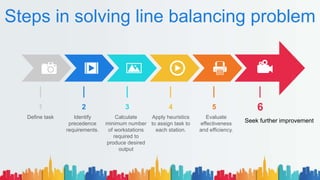
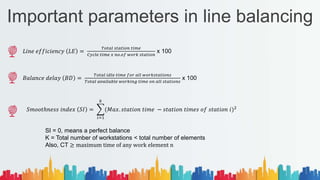
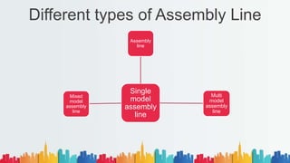
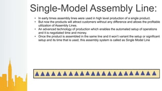
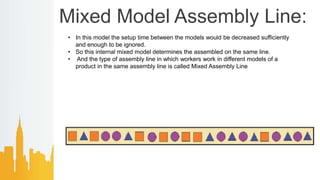
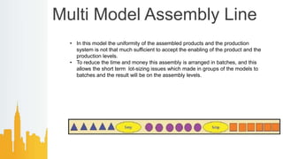
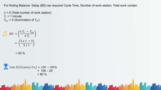
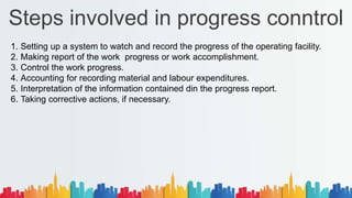
Industrial Engineering (2161907)
Faculty Name: Girish Brahmkshtriya
Topics Cover
01 Introduction to line of balance
02 Assembly line balancing
03 Progress control
04
05
Line Balancing
• Assembly line balancing is associated
with a product layout in which products
are processed as they pass through a
line of work centers.
• An assembly line can be considered as
a "PRODUCTION SEQUENCE" where
parts are assembled together to form an
end product.
• The operations are carried out at
different workstations situated along the
line.
Advantages And Disadvantages
1. Uniform rate of production.
2. Less material handling.
3. Less work-in-process.
4. Easy production control.
5. Effective use of facilities/ labour.
6. Less congestion.
Advantages
1. More capital intensive (i.e., demands
larger investments).
2. Low flexibility.
3. Monotony of work for operators.
Disadvantages
The Problem of Line Balancing arises due to the following factors
The finished product is the result of many sequential operations.
Line balancing is the apportionment of sequential work activities into
workstations in order to gain a high utilization of labor and equipment
so as to minimize the idle time.
There is a difference in production capacities of different machines
(The output from different machines is not identical).
01
02
Note
Understanding Example
The production capacities of two machines, lathe and milling is as under for
a particular job.
Lathe - 50 pieces/hour
Milling - 25 pieces/hour
Now if only one machine of each is provided, then machine B will produce 25 units/
hour where as the machine A can produce 50 units. But because of the sequence, only
25 units are produced per hour, i.e., machine A will work only 50 per cent of its capacity
and the remaining 30 minutes in one hour, it is idle. This idle time can be minimised by
introducing one more machine of kind B in the production line.
Some important definition
Workstation
A work station is a location on assembly line where given amount of
work is performed
Task
The smallest grouping of work that can be assigned to a workstation
Cycle time
It is the amount of time for which a unit that is assembled is available
Plant Layout to any operator on the line or it is the time the product
spends at each work station
01
02
03
𝐶𝑦𝑐𝑙𝑒 𝑡𝑖𝑚𝑒 𝐶𝑇 =
𝐴𝑣𝑎𝑖𝑙𝑎𝑏𝑙𝑒 𝑡𝑖𝑚𝑒 𝑝𝑒𝑟𝑖𝑜𝑑
𝑜𝑢𝑡𝑝𝑢𝑡 𝑢𝑛𝑖𝑡𝑠 𝑟𝑒𝑞𝑢𝑖𝑟𝑒𝑑 𝑝𝑒𝑟𝑖𝑜𝑑
=
𝐴𝑇
𝑂𝑢𝑡𝑝𝑢𝑡
Continue
Predecessor task
A task that must be performed before performing another
(successor) task.
Balance Delay (BD)
Percentage of total idle time on the line to total time spent by
the product from beginning to end of line
Task time (ti)
Standard time to perform element task.
Station time (sk)
Total standard work content of specific workstation
04
05
06
07
Balance Time Equation
𝐵. 𝐷 =
𝑛. 𝐶𝑇 − 𝑘=1
𝑛
𝑠𝑘 𝑥 100
𝑛 𝑥 𝐶𝑇
B.D = Balanced delay
n = Number of work station
CT = Cycle time
Sk = Station time
Steps in solving line balancing problem
6
5
4
3
2
1
Define task Identify
precedence
requirements.
Calculate
minimum number
of workstations
required to
produce desired
output
Apply heuristics
to assign task to
each station.
Evaluate
effectiveness
and efficiency.
Seek further improvement
Important parameters in line balancing
𝐿𝑖𝑛𝑒 𝑒𝑓𝑓𝑖𝑐𝑖𝑒𝑛𝑐𝑦 𝐿𝐸 =
𝑇𝑜𝑡𝑎𝑙 𝑠𝑡𝑎𝑡𝑖𝑜𝑛 𝑡𝑖𝑚𝑒
𝐶𝑦𝑐𝑙𝑒 𝑡𝑖𝑚𝑒 𝑥 𝑛𝑜.𝑜𝑓 𝑤𝑜𝑟𝑘 𝑠𝑡𝑎𝑡𝑖𝑜𝑛
x 100
𝐵𝑎𝑙𝑎𝑛𝑐𝑒 𝑑𝑒𝑙𝑎𝑦 𝐵𝐷 =
𝑇𝑜𝑡𝑎𝑙 𝑖𝑑𝑙𝑒 𝑡𝑖𝑚𝑒 𝑓𝑜𝑟 𝑎𝑙𝑙 𝑤𝑜𝑟𝑘𝑠𝑡𝑎𝑡𝑖𝑜𝑛𝑠
𝑇𝑜𝑡𝑎𝑙 𝑎𝑣𝑎𝑖𝑙𝑎𝑏𝑙𝑒 𝑤𝑜𝑟𝑘𝑖𝑛𝑔 𝑡𝑖𝑚𝑒 𝑜𝑛 𝑎𝑙𝑙 𝑠𝑡𝑎𝑡𝑖𝑜𝑛𝑠
x 100
𝑆𝑚𝑜𝑜𝑡ℎ𝑛𝑒𝑠𝑠 𝑖𝑛𝑑𝑒𝑥 𝑆𝐼 =
𝑖=1
𝑘
(𝑀𝑎𝑥. 𝑠𝑡𝑎𝑡𝑖𝑜𝑛 𝑡𝑖𝑚𝑒 − 𝑠𝑡𝑎𝑡𝑖𝑜𝑛 𝑡𝑖𝑚𝑒𝑠 𝑜𝑓 𝑠𝑡𝑎𝑡𝑖𝑜𝑛 𝑖)2
SI = 0, means a perfect balance
K = Total number of workstations < total number of elements
Also, CT ≥ maximum time of any work element n
Different types of Assembly Line
Single
model
assembly
line
Assembly
line
Multi
model
assembly
line
Mixed
model
assembly
line
Single-Model Assembly Line:
• In early times assembly lines were used in high level production of a single product.
• But now the products will attract customers without any difference and allows the profitable
utilization of Assembly Lines.
• An advanced technology of production which enables the automated setup of operations
and it is negotiated time and money.
• Once the product is assembled in the same line and it won’t variant the setup or significant
setup and its time that is used, this assembly system is called as Single Model Line
Mixed Model Assembly Line:
• In this model the setup time between the models would be decreased sufficiently
and enough to be ignored.
• So this internal mixed model determines the assembled on the same line.
• And the type of assembly line in which workers work in different models of a
product in the same assembly line is called Mixed Assembly Line
Multi Model Assembly Line
• In this model the uniformity of the assembled products and the production
system is not that much sufficient to accept the enabling of the product and the
production levels.
• To reduce the time and money this assembly is arranged in batches, and this
allows the short term lot-sizing issues which made in groups of the models to
batches and the result will be on the assembly levels.
Heuristic Method of Assembly line Balancing
In this method, numbers are assigned to each operation to denote how many predecessors
it has. Those operations showing the lowest predecessor number are taken first on the
workstations.
Steps :-
1. Draw the precedence diagram of work elements first and then succeeding elements.
Elements within the columns are assigned to workstation after all the elements of
previous columns have been assigned.
2. Select cycle time (CT) which is feasible
𝑇𝑚𝑎𝑥 ≤ 𝐶𝑇 ≤ 𝑖=1 𝑛 𝑇𝑖
𝑇𝑖 = Time for work element
n = Number of work element
𝑇𝑚𝑎𝑥 = Maximum work element time
CT = Cycle time
3. Assign work elements to workstations sum of elemental times should not exceed cycle time (CT) while doing so
proceed from column Ito column II and so on. Break intra column tie by using minimum number of precedence.
4. Deduct assigned work elements from total elements. Repeat step (3).
5. If workstations (ws) time is more than CT, identify work element due to which this happens and carry it forward
to next workstation
6. Repeat steps (3) to (5) till all elements are fully assigned
Example
Draw the precedence diagram, Balance the line & Find Balance Delay (B.D), Line Efficiency, Smoothness Index
Cycle time – 1 Minute
Element 𝑻𝒊 Precedence
1 0.2 -
2 0.4 -
3 0.7 1
4 0.1 1,2
5 0.3 2
6 0.11 3
7 0.32 3
8 0.60 3,4
9 0.27 6,7,8
10 0.38 5,8
11 0.51 9,10
12 0.11 11
Precedence Diagram
1
3
2
4
6
11
8
7
5
10
9
12
0.2
0.4
0.1
0.7
0.3
0.60
0.32
0.11
0.2
7
0.38
0.51 0.11
List all the elements in decreasing order of that task time (𝑇𝑖)
Element 𝑻𝒊 Precedence
3 0.7 1
8 0.60 3,4
11 0.51 9,10
2 0.4 -
10 0.38 5,8
7 0.32 3
5 0.3 2
9 0.27 6,7,8
1 0.2 -
6 0.11 3
12 0.11 11
4 0.1 1,2
 Assign elements in work station
 Start from starting point and end at ending point of list
 Notes: Precedence required
Workstation time should not exceed cycle time (Here cycle time is 1 Minute)
Work
Station
Element 𝑻𝒊 𝑻𝒔𝒊 Idle Time
I 2 0.4 1.0 0
5 0.3
1 0.2
4 0.1
II 3 0.7 0.81 0.19
6 0.11
III 8 0.6 0.98 0.02
10 0.38
IV 7 0.32 0.59 0.41
9 0.27
V 11 0.51 0.62 0.38
12 0.11
For finding Balance Delay (BD) we required Cycle Time, Number of work station, Total work contain
n = 5 (Total number of work station)
𝑇𝑐 = 1 minute
𝑇𝑤𝑐 = 4 (Summation of 𝑇𝑠𝑖)
𝐵𝐷 =
𝑛 𝑇𝑐 − 𝑇𝑤𝑐
𝑛 𝑇𝑐
=
5 𝑥 1 − 4
5 𝑥 1
= 20 %
𝐿𝑖𝑛𝑒 𝐸𝑓𝑓𝑖𝑐𝑖𝑒𝑛𝑐𝑦 ∩𝑙 = 100 − 𝐵𝐷%
= 100 – 20
= 80 %
Progress Control
• Progress control is nothing but the continuous follow up of the issued orders.
• It is very important to regulate the progress of job through various processes.
• This function is also called “Follow-up”.
• The function of progress control is to report daily progress of the work in each shop in a prescribed format
and investigate the causes of deviation from the planned performance.
• Progress control monitors the production schedule and attempts to match with the delivery schedule.
• Progress control is required for material, components and assembly.
• Each and every aspect of the job progress is to be continually monitored.
• If any deviation found it is required to settle it, such that production schedule should met.
• The causes of delay may be:
1. Shortage and unavailability of raw material
2. Shut down of equipments.
3. Shortage of tools, gauges, jigs and fixtures etc.
4. Higher amount of rework.
5. Errors in routing , scheduling and dispatching.
Steps involved in progress conntrol
1. Setting up a system to watch and record the progress of the operating facility.
2. Making report of the work progress or work accomplishment.
3. Control the work progress.
4. Accounting for recording material and labour expenditures.
5. Interpretation of the information contained din the progress report.
6. Taking corrective actions, if necessary.
Thank you
Questions And Suggestions Are
Accepted

Industrial engineeering pli

  • 1.
    Industrial Engineering (2161907) FacultyName: Girish Brahmkshtriya
  • 2.
    Topics Cover 01 Introductionto line of balance 02 Assembly line balancing 03 Progress control 04 05
  • 3.
    Line Balancing • Assemblyline balancing is associated with a product layout in which products are processed as they pass through a line of work centers. • An assembly line can be considered as a "PRODUCTION SEQUENCE" where parts are assembled together to form an end product. • The operations are carried out at different workstations situated along the line.
  • 4.
    Advantages And Disadvantages 1.Uniform rate of production. 2. Less material handling. 3. Less work-in-process. 4. Easy production control. 5. Effective use of facilities/ labour. 6. Less congestion. Advantages 1. More capital intensive (i.e., demands larger investments). 2. Low flexibility. 3. Monotony of work for operators. Disadvantages
  • 5.
    The Problem ofLine Balancing arises due to the following factors The finished product is the result of many sequential operations. Line balancing is the apportionment of sequential work activities into workstations in order to gain a high utilization of labor and equipment so as to minimize the idle time. There is a difference in production capacities of different machines (The output from different machines is not identical). 01 02 Note
  • 6.
    Understanding Example The productioncapacities of two machines, lathe and milling is as under for a particular job. Lathe - 50 pieces/hour Milling - 25 pieces/hour Now if only one machine of each is provided, then machine B will produce 25 units/ hour where as the machine A can produce 50 units. But because of the sequence, only 25 units are produced per hour, i.e., machine A will work only 50 per cent of its capacity and the remaining 30 minutes in one hour, it is idle. This idle time can be minimised by introducing one more machine of kind B in the production line.
  • 7.
    Some important definition Workstation Awork station is a location on assembly line where given amount of work is performed Task The smallest grouping of work that can be assigned to a workstation Cycle time It is the amount of time for which a unit that is assembled is available Plant Layout to any operator on the line or it is the time the product spends at each work station 01 02 03 𝐶𝑦𝑐𝑙𝑒 𝑡𝑖𝑚𝑒 𝐶𝑇 = 𝐴𝑣𝑎𝑖𝑙𝑎𝑏𝑙𝑒 𝑡𝑖𝑚𝑒 𝑝𝑒𝑟𝑖𝑜𝑑 𝑜𝑢𝑡𝑝𝑢𝑡 𝑢𝑛𝑖𝑡𝑠 𝑟𝑒𝑞𝑢𝑖𝑟𝑒𝑑 𝑝𝑒𝑟𝑖𝑜𝑑 = 𝐴𝑇 𝑂𝑢𝑡𝑝𝑢𝑡
  • 8.
    Continue Predecessor task A taskthat must be performed before performing another (successor) task. Balance Delay (BD) Percentage of total idle time on the line to total time spent by the product from beginning to end of line Task time (ti) Standard time to perform element task. Station time (sk) Total standard work content of specific workstation 04 05 06 07
  • 9.
    Balance Time Equation 𝐵.𝐷 = 𝑛. 𝐶𝑇 − 𝑘=1 𝑛 𝑠𝑘 𝑥 100 𝑛 𝑥 𝐶𝑇 B.D = Balanced delay n = Number of work station CT = Cycle time Sk = Station time
  • 10.
    Steps in solvingline balancing problem 6 5 4 3 2 1 Define task Identify precedence requirements. Calculate minimum number of workstations required to produce desired output Apply heuristics to assign task to each station. Evaluate effectiveness and efficiency. Seek further improvement
  • 11.
    Important parameters inline balancing 𝐿𝑖𝑛𝑒 𝑒𝑓𝑓𝑖𝑐𝑖𝑒𝑛𝑐𝑦 𝐿𝐸 = 𝑇𝑜𝑡𝑎𝑙 𝑠𝑡𝑎𝑡𝑖𝑜𝑛 𝑡𝑖𝑚𝑒 𝐶𝑦𝑐𝑙𝑒 𝑡𝑖𝑚𝑒 𝑥 𝑛𝑜.𝑜𝑓 𝑤𝑜𝑟𝑘 𝑠𝑡𝑎𝑡𝑖𝑜𝑛 x 100 𝐵𝑎𝑙𝑎𝑛𝑐𝑒 𝑑𝑒𝑙𝑎𝑦 𝐵𝐷 = 𝑇𝑜𝑡𝑎𝑙 𝑖𝑑𝑙𝑒 𝑡𝑖𝑚𝑒 𝑓𝑜𝑟 𝑎𝑙𝑙 𝑤𝑜𝑟𝑘𝑠𝑡𝑎𝑡𝑖𝑜𝑛𝑠 𝑇𝑜𝑡𝑎𝑙 𝑎𝑣𝑎𝑖𝑙𝑎𝑏𝑙𝑒 𝑤𝑜𝑟𝑘𝑖𝑛𝑔 𝑡𝑖𝑚𝑒 𝑜𝑛 𝑎𝑙𝑙 𝑠𝑡𝑎𝑡𝑖𝑜𝑛𝑠 x 100 𝑆𝑚𝑜𝑜𝑡ℎ𝑛𝑒𝑠𝑠 𝑖𝑛𝑑𝑒𝑥 𝑆𝐼 = 𝑖=1 𝑘 (𝑀𝑎𝑥. 𝑠𝑡𝑎𝑡𝑖𝑜𝑛 𝑡𝑖𝑚𝑒 − 𝑠𝑡𝑎𝑡𝑖𝑜𝑛 𝑡𝑖𝑚𝑒𝑠 𝑜𝑓 𝑠𝑡𝑎𝑡𝑖𝑜𝑛 𝑖)2 SI = 0, means a perfect balance K = Total number of workstations < total number of elements Also, CT ≥ maximum time of any work element n
  • 12.
    Different types ofAssembly Line Single model assembly line Assembly line Multi model assembly line Mixed model assembly line
  • 13.
    Single-Model Assembly Line: •In early times assembly lines were used in high level production of a single product. • But now the products will attract customers without any difference and allows the profitable utilization of Assembly Lines. • An advanced technology of production which enables the automated setup of operations and it is negotiated time and money. • Once the product is assembled in the same line and it won’t variant the setup or significant setup and its time that is used, this assembly system is called as Single Model Line
  • 14.
    Mixed Model AssemblyLine: • In this model the setup time between the models would be decreased sufficiently and enough to be ignored. • So this internal mixed model determines the assembled on the same line. • And the type of assembly line in which workers work in different models of a product in the same assembly line is called Mixed Assembly Line
  • 15.
    Multi Model AssemblyLine • In this model the uniformity of the assembled products and the production system is not that much sufficient to accept the enabling of the product and the production levels. • To reduce the time and money this assembly is arranged in batches, and this allows the short term lot-sizing issues which made in groups of the models to batches and the result will be on the assembly levels.
  • 16.
    Heuristic Method ofAssembly line Balancing In this method, numbers are assigned to each operation to denote how many predecessors it has. Those operations showing the lowest predecessor number are taken first on the workstations. Steps :- 1. Draw the precedence diagram of work elements first and then succeeding elements. Elements within the columns are assigned to workstation after all the elements of previous columns have been assigned. 2. Select cycle time (CT) which is feasible 𝑇𝑚𝑎𝑥 ≤ 𝐶𝑇 ≤ 𝑖=1 𝑛 𝑇𝑖 𝑇𝑖 = Time for work element n = Number of work element 𝑇𝑚𝑎𝑥 = Maximum work element time CT = Cycle time
  • 17.
    3. Assign workelements to workstations sum of elemental times should not exceed cycle time (CT) while doing so proceed from column Ito column II and so on. Break intra column tie by using minimum number of precedence. 4. Deduct assigned work elements from total elements. Repeat step (3). 5. If workstations (ws) time is more than CT, identify work element due to which this happens and carry it forward to next workstation 6. Repeat steps (3) to (5) till all elements are fully assigned
  • 18.
    Example Draw the precedencediagram, Balance the line & Find Balance Delay (B.D), Line Efficiency, Smoothness Index Cycle time – 1 Minute
  • 19.
    Element 𝑻𝒊 Precedence 10.2 - 2 0.4 - 3 0.7 1 4 0.1 1,2 5 0.3 2 6 0.11 3 7 0.32 3 8 0.60 3,4 9 0.27 6,7,8 10 0.38 5,8 11 0.51 9,10 12 0.11 11
  • 20.
  • 21.
    List all theelements in decreasing order of that task time (𝑇𝑖) Element 𝑻𝒊 Precedence 3 0.7 1 8 0.60 3,4 11 0.51 9,10 2 0.4 - 10 0.38 5,8 7 0.32 3 5 0.3 2 9 0.27 6,7,8 1 0.2 - 6 0.11 3 12 0.11 11 4 0.1 1,2
  • 22.
     Assign elementsin work station  Start from starting point and end at ending point of list  Notes: Precedence required Workstation time should not exceed cycle time (Here cycle time is 1 Minute)
  • 23.
    Work Station Element 𝑻𝒊 𝑻𝒔𝒊Idle Time I 2 0.4 1.0 0 5 0.3 1 0.2 4 0.1 II 3 0.7 0.81 0.19 6 0.11 III 8 0.6 0.98 0.02 10 0.38 IV 7 0.32 0.59 0.41 9 0.27 V 11 0.51 0.62 0.38 12 0.11
  • 24.
    For finding BalanceDelay (BD) we required Cycle Time, Number of work station, Total work contain n = 5 (Total number of work station) 𝑇𝑐 = 1 minute 𝑇𝑤𝑐 = 4 (Summation of 𝑇𝑠𝑖) 𝐵𝐷 = 𝑛 𝑇𝑐 − 𝑇𝑤𝑐 𝑛 𝑇𝑐 = 5 𝑥 1 − 4 5 𝑥 1 = 20 % 𝐿𝑖𝑛𝑒 𝐸𝑓𝑓𝑖𝑐𝑖𝑒𝑛𝑐𝑦 ∩𝑙 = 100 − 𝐵𝐷% = 100 – 20 = 80 %
  • 25.
    Progress Control • Progresscontrol is nothing but the continuous follow up of the issued orders. • It is very important to regulate the progress of job through various processes. • This function is also called “Follow-up”. • The function of progress control is to report daily progress of the work in each shop in a prescribed format and investigate the causes of deviation from the planned performance. • Progress control monitors the production schedule and attempts to match with the delivery schedule. • Progress control is required for material, components and assembly. • Each and every aspect of the job progress is to be continually monitored. • If any deviation found it is required to settle it, such that production schedule should met. • The causes of delay may be: 1. Shortage and unavailability of raw material 2. Shut down of equipments. 3. Shortage of tools, gauges, jigs and fixtures etc. 4. Higher amount of rework. 5. Errors in routing , scheduling and dispatching.
  • 26.
    Steps involved inprogress conntrol 1. Setting up a system to watch and record the progress of the operating facility. 2. Making report of the work progress or work accomplishment. 3. Control the work progress. 4. Accounting for recording material and labour expenditures. 5. Interpretation of the information contained din the progress report. 6. Taking corrective actions, if necessary.
  • 27.
    Thank you Questions AndSuggestions Are Accepted