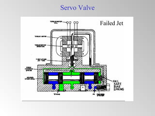
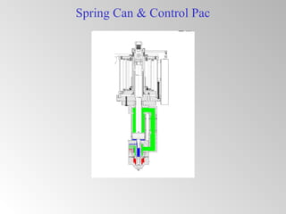
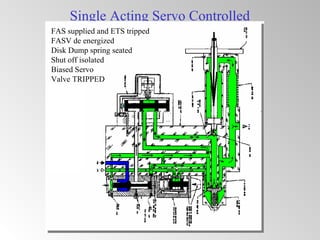
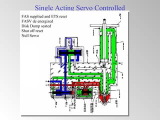
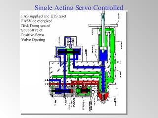
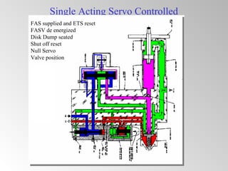
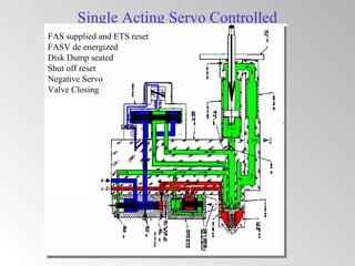
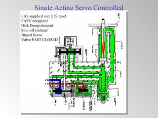
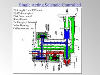
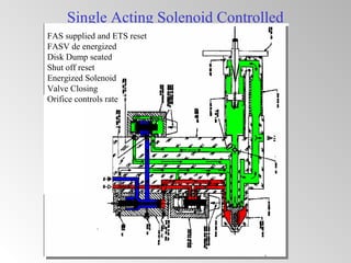
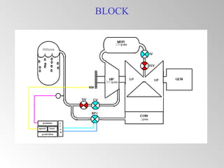
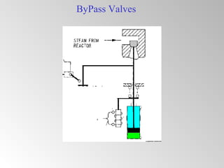
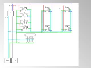
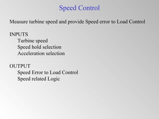
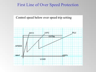
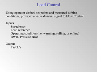
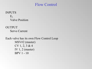
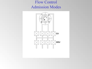
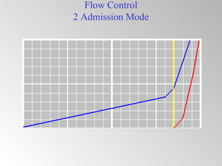
The document discusses steam turbine governor systems and controls. It describes how governors regulate steam flow to maintain desired turbine speed even as load torque changes. It also describes emergency controls to reduce steam flow if load is lost to prevent overspeed, or trip the turbine if speed cannot be controlled. The document then summarizes various turbine control components, including hydraulic and electronic controls, valves, actuators and their functions in speed control, load control, flow control and overspeed protection.
The presentation discuss about the operations, causes and remedies for the facing emergencies of steam Turbines. Specially for the 210MW LMW units. The emergencies can be created on simulator and studied on the simulator ACCORDINGLY.
The discussion on "Handling of Turbines During Emergencies" has been detailed in the ppt. Some case studies are also discussed in the session where the course participants express their difficulties while coming across the emergencies in handling the turbines at their locations.
Turbine Stress Control Logic, Calculation & WorkingTahoor Alam Khan
Turbine Stress Control is one of the complex logics of BHEL turbine. This presentation clearly explains the Logic, working, calculations and influence of the same on operation of steam turbine. For further details and understanding, I can be reached on tahoorkhn03@gmail.com.
This deals with Boiler feed pumps used in power plants .
contains details about the KHI and FK series pumps , technical parameters and maintenance prctices followed for these pumps
Boiler purge is the basic process of resetting boiler before lightup. This presentation explains the logic, schematics & working of purge procedure. For enhanced knowledge of this topic, I can be reached at tahoorkhn03@gmail.com.
Thermal Power Plant Simulator, Cold, warm and Hot rolling of Steam TurbineManohar Tatwawadi
The presentation describes the cold rolling, warm rolling and hot rolling and synchronising of steam turbine. The Temperature Matching Chart for Turbine metal and Steam is also discussed in the presentation
A steam turbine is a prime mover in which the potential energy of the steam is transformed into kinetic energy and later in its turn is transformed into the mechanical energy of rotation of the turbine shaft
Unit 6- Governers , Dynamics of machines of VTU Syllabus prepared by Hareesha N Gowda, Asst. Prof, Dayananda Sagar College of Engg, Blore. Please write to hareeshang@gmail.com for suggestions and criticisms.
The valve timing of modern automobiles are not constant. It varies with speed, load. Here this slide describes about the modern Variable Valve Timing system and their controls
A COMPREHENSIVE STUDY ON GOVERNING OF HYDRAULIC TURBINESMayurjyotiNeog
This short presentation consists of a brief study on governing of hydraulic turbines, different governing components & governing systems used in India.
1. Steam Turbine Governor
Regulate STEAM FLOW into TURBINE such that at the desired
SPEED the OUTPUT TORQUE of the Turbine is exactly equal
the LOAD Torque of the Generator
(If torque is not equal the result is a change in speed – Newton’s Law)
In the event of sudden LOAD TORQUE loss, Quickly reduce
STEAM FLOW to maintain desired SPEED below Emergency
trip Speed
(excessive TURBINE OUTPUT TORQUE results in rapid speed increase)
In the event of a complete failure of speed control, emergency
over speed governor shall limit speed less than 120%
2. Steam Turbine Controls
Provide a means to prewarm
Provide a means to accelerate to speed and synchronize
Provide a means to control flow for MW generation
Provide a means to protect the equipment from adverse operating
conditions
Provide a means to test components to ensure operability
3. Turbine Control Hydraulics
Hydraulic Power Unit
Provide high pressure fluid to control the turbine valves
FAS (power for actuator positioning)
ETS (logic for tripping)
Lube Oil System
Provide front standard trip logic
Servo Valves
Solenoid Valves
Actuators
Steam valves
Front standard
10. Single Acting Servo Controlled
FAS supplied and ETS tripped
FASV de energized
Disk Dump spring seated
Shut off isolated
Biased Servo
Valve TRIPPED
11. Single Acting Servo Controlled
FAS supplied and ETS reset
FASV de energized
Disk Dump seated
Shut off reset
Null Servo
12. Single Acting Servo Controlled
FAS supplied and ETS reset
FASV de energized
Disk Dump seated
Shut off reset
Positive Servo
Valve Opening
13. Single Acting Servo Controlled
FAS supplied and ETS reset
FASV de energized
Disk Dump seated
Shut off reset
Null Servo
Valve position
14. Single Acting Servo Controlled
FAS supplied and ETS reset
FASV de energized
Disk Dump seated
Shut off reset
Negative Servo
Valve Closing
15. Single Acting Servo Controlled
FAS supplied and ETS reset
FASV energized
Disk Dump dumped
Shut off isolated
Biased Servo
Valve FAST CLOSED
16. Single Acting Solenoid Controlled
FAS supplied and ETS reset
FASV de energized
Disk Dump seated
Shut off reset
De Energized Solenoid
Valve Opening
Orifice controls rate
17. Single Acting Solenoid Controlled
FAS supplied and ETS reset
FASV de energized
Disk Dump seated
Shut off reset
Energized Solenoid
Valve Closing
Orifice controls rate
21. Main Control ValvesMain Control Valves
Purpose: To regulate steam flow to the HP
turbine.
• Control turbine speed (Speed Governor) or,
• Control generator load (Load Control) or,
• Control Reactor pressure (Pressure Governor)
1st
axiom of Turbine Controls-
One valve can control only one variable at one time
27. Intercept ValvesIntercept Valves
Primary Purpose: To regulate steam flow to the
IP (LP) turbine in an overspeed where the control
valves have been closed and speed continues to
increase. Also, to blow down reheater and/or
steam piping prior to opening of control valves.
30. ByPass Valves
Purpose: Regulate reactor steam flow to the condenser,
when steam flow is not needed by the turbine
BPV use a simple double acting actuator (no ETS supply)
1) can be manualy opened during intial criticallity
2) regulated by Pressure Control over range of 150
to 1050 psig
33. Speed Control
Measure turbine speed and provide Speed error to Load Control
INPUTS
Turbine speed
Speed hold selection
Acceleration selection
OUTPUT
Speed Error to Load Control
Speed related Logic
34. First Line of Over Speed Protection
Control speed below over speed trip setting
35. Load Control
Using operator desired set points and measured turbine
conditions, provided a valve demand signal to Flow Control
Inputs
Speed error
Load reference
Operating condition (i.e. warming, rolling, or online)
BWR- Pressure error
Output
EsubL’s
40. Protection (trips)
Vital
Loss of Life
Redundant tripping and testable
Important
Loss of Capital
2 out of 3 logic for increased availability
Operational
Increased maintenance
Pre alarm
41. Second Line of Over Speed Protection
If First fails
Limit Peak Speed Below 120%