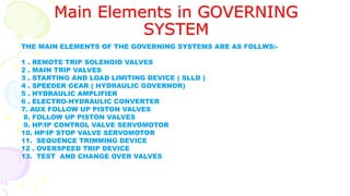
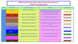
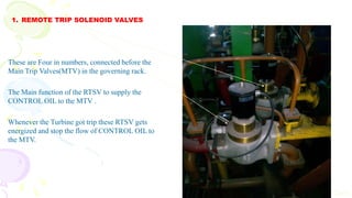
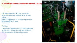
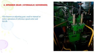
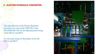
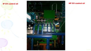
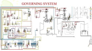
INTRODUCTION TO
GOVERNING
SYSTEM
By :
SURAJ KUMAR
16PG047
Content :
1. Governing System.
2. Types OF Governing System.
3. Features Of KWU Turbine Governing System.
4. Turbine Oil System Interlocks.
5. Main Elements of Governing System.
6. Different Oil and there Colour Codes in KWU Turbine Governing.
7. Automatic Turbine Testing ( ATT).
8. Conclusion.
What is a governing system ?
To govern means to control and regulate certain parameters to achieve expected
functional requirements.
In the context of thermal power plant, Governing system of steam turbine can be
defined as a control and regulatory mechanism whose objective is to enable turbo
generator unit to produce quality power with safe operation and to achieve functional
requirements of turbo-generator operation by controlling and regulating steam turbine
input parameters viz. inlet pressure and mass flow rate of steam.
Types Of GOVERNING SYSTEM
On the basis of steam admission method governing
system of utility steam is classified into the
following types:-
1. Nozzle Governing.
2. Throttle Governing.
Most of the LMW turbine have Nozzle Governing and
Maximum of KWU turbine have Throttle Governing.
The throttling Governing in KWU Turbine is taken palace by regulating the opening and closing of the
CONTROL VALVES present at the inlet of Turbine.
This throttling is taken place by the help of regulating oil pressure.
At the initial start of the Turbine Governing oil which is also known as Control Oil is supply by the
Auxiliary Oil Pump ( from 0 RPM to 2800 Rpm) and after 2800 Rpm this control oil is supply by the
Main Oil Pump mounted on the Turbine shaft.
Cont.
Features Of Governing System
The Turbine Governing System meet the demand of precise control with high response
and safety.
• Safe operation of turbine during load change period.
• Throttling method is used to regulate steam flow a/c to the load demand. Throttling is
done at Control Valve of HP or IP Turbine.
• Automatic Turbine Tester is provided to check the operation of protective devices
and closing of ESV, CV while machine in service.
Turbine Oil System interlocks
BARRING
GEAR ON
BARRING
GEAR VAL
OPEN
BARRING
GEAR OFF
JOP-1 Start & Oil Pre > 150 kg/cm2
If Oil Pre falls < 150 kg/cm2 for 7
Sec JOP – 2 will Start
BARRING
GEAR ON
Oil Pre < 4.8 ksc – AOP – 1 Start
Oil Pre < 4.5 ksc – AOP – 2 Start
Oil Pre < 1.1 ksc – EOP - 1 Start
JOP
OFF
SOAKING
600 RPM on 250 MW
120 RPM
< 510 RPM
> 240 RPM > 540 RPM
> 2850 RPM
& Oil Pre > 7 kg/cm2
< 210 RPM
120 RPM
AOP
OFF
SYNCRONIZATION
SPEED 3000 RPM
WHEN TRIPPED
MOP @ 9 ksc
AOP - 2 Nos – AC - Oil Pre @ 7 kg/cm2
JOP – 2Nos – JOP-1- AC & JOP-2 - DC - Oil Pre @ 178 kg/cm2
EPO – 2 Nos - EOP-1- DC & EOP-2 – AC – Oil Pre @ 2.3 kg/cm2
OIL Grade - SERVO PRIME - 46
Emergency Oil Pump Jacking Oil Pump
Emergency Oil Pump ( EOP).
 Two numbers of pump of
2x100% capacity.
 1 AC and 1 DC.
 Discharge Oil pressure is
approx. 2.3 Kg/cm2
 Mainly used a backup
pump.
Jacking Oil Pump ( JOP).
 Two numbers of pump of
2x100% capacity.
 1 AC and 1 DC.
 Discharge Oil pressure is
approx. 170 Kg/cm2
 Mainly responsible for
lifting of Turbine shaft and
lubricating of Turbine shaft
in initial condition before
540Rpm
Auxiliary Oil Pump
Auxiliary Oil Pump ( EOP).
 Two numbers of pump of 1x100% capacity.
 Both are AC pump.
 Discharge Oil pressure is approx. 6-7
Kg/cm2
 Mainly responsible for supplying
CONTROL OIL ( From 0 – 2850 Rpm),
Lifting of turbine shaft (after 540Rpm) and
Lubrication.
Main Oil Pump
Main Oil Pump ( MOP).
 One number of pump of
1x100% capacity.
 Mounted on Turbine shaft.
 Discharge Oil pressure is
approx. 8-9Kg/cm2
 Mainly responsible for
Lubrication and Control Oil
Supply ( >2850 Rpm).
Main Elements in GOVERNING
SYSTEM
THE MAIN ELEMENTS OF THE GOVERNING SYSTEMS ARE AS FOLLWS:-
1 . REMOTE TRIP SOLENOID VALVES
2 . MAIN TRIP VALVES
3 . STARTING AND LOAD LIMITING DEVICE ( SLLD )
4 . SPEEDER GEAR ( HYDRAULIC GOVERNOR)
5 . HYDRAULIC AMPLIFIER
6 . ELECTRO-HYDRAULIC CONVERTER
7. AUX FOLLOW UP PISTON VALVES
8. FOLLOW UP PISTON VALVES
9. HP/IP CONTROL VALVE SERVOMOTOR
10. HP/IP STOP VALVE SERVOMOTOR
11. SEQUENCE TRIMMING DEVICE
12 . OVERSPEED TRIP DEVICE
13. TEST AND CHANGE OVER VALVES
S.No Name of Oil Source & pressure Purpose Colour Code
1. Control Oil MOP/AOP ( 7-8.5 Kg/cm2) To establish Trip Oil, Aux Trip Oil, Trip Oil,
Start-up Oil, Aux Start-up Oil, Aux Secondary
Oil, Secondary Oil, Primary Oil, Etc
2.
Trip Oil
Main Trip Valve (4.8-6 Kg/cm2) To reset , Open & Trip stop valve
3.
Aux Trip Oil
Main Trip Valve (4.8-6 Kg/cm2) To trip Hydraulic Trip Device
4.
Start-up Oil
Starting Device ( 5.5 Kg/cm2) To assist Resetting & Opening Stop Valves
5.
Aux Start-up Oil
Starting Device ( 5.5 Kg/cm2) To Reset Main Trip Valve & Hydraulic Trip
Device
6.
Aux Secondary Oil
Speeder Gear ( 2.3-4.8 Kg/cm2) Input Signal to Hydraulic Converter
7.
Secondary Oil
(HP/IP)
Hyd/Electro-Hyd Converter ( 0-6 Kg/cm2) To govern HP/IP Control Valve opening
8.
Primary Oil
Primary Oil Pump ( 0-2.3 Kg/cm2) Feedback speed signal for HG
9.
Test Oil
Over Speed Test Device ( 2.0 Kg/cm2) To test Over Speed Test Device
10.
Drains
Different oils, their colour codes, sources and purpose in
KWU Governing System
1. REMOTE TRIP SOLENOID VALVES
Cont
These are Four in numbers, connected before the
Main Trip Valves(MTV) in the governing rack.
The Main function of the RTSV to supply the
CONTROL OIL to the MTV .
Whenever the Turbine got trip these RTSV gets
energized and stop the flow of CONTROL OIL to
the MTV.
2. MAIN TRIP VALVES
Cont
These are two in numbers present in the series
connection with the RTSV.
The main function is to generate TRIP OIL and
AUXILIARY TRIP OIL.
The Function of trip oil is to reset or open the Stop
valves and to work as the source for the
HYDRAULIC AND ELECTRO-HYDRAULIC
CONVERTER.
The Function of Auxiliary trip oil is to trip the
Hydraulic device.
3. STARTING AND LOAD LIMITING DEVICE ( SLLD )
Cont
The Main function of SLLD is to reset the
protective device and latch the HP & IP Stop
valves.
At SLLD opening of 42 % HP SV Open and at
56% opening IP SV open.
Working:
Control oil is supplied to SLLD which generates
AUXILIARY START-UP OIL and START-UP
OIL for protective device and stop valve.
4. SPEEDER GEAR ( HYDRAULIC GOVERNOR)
Cont
Also known as adjusting gear, used to manual or
motor operation of reference speed setter and
SLLD.
5. ELECTRO-HYDRAULIC CONVERTER.
Cont
The main function of the Electro-Hydraulic
converter is to convert the TRIP OIL to the
SECONDARY OIL for the Opening and Closing
of the HP CV and IPCV.
It is the main source of Secondary oil for the
HPCV and IPCV.
IP CV control oil HP CV control oil
Cont
6. HYDRAULIC CONVERTER.
Follow UP-Piston
Con
The main function of the Hydraulic converter is to
convert the TRIP OIL to the SECONDARY OIL
for the Opening and Closing of the HP CV and
IPCV.
It is the backup source of Secondary oil for the
HPCV and IPCV besides Electro-hydraulic
converter.
IP CV control oil HP CV control oil
Cont
7. TRIM DEVICE
Cont
The main function of the
TRIM DEVIVE is to cut the
flow of the IP Control Oil
and reduce the opening of the
IPCV.
8. HP ESV/ CV
9. SERVOMOTOR
Cont
10. CHANGE OVER VALVE
11.OVERSPEED TRIP DEVICE
Cont
GOVERNING SYSTEM
Automatic Turbine Testing(ATT)
ATT plays a vital role in the Governing System.
ATT is responsible for the safety and proper working of the elements of the Governing
System .
Its unable us to test the safe operation of the turbine by testing different elements of the
Governing System such as :
1. ESV .
2. CV.
3. MTV.
4. Over Speed Trip devices.
Conclusion
The Governing System act as the Back Bone of any Turbo Generator Unit as it not only control and regulate
the steam parameters according to the load but also responsible for the safety and safe operation of the
Turbine.
INTRODUCTION TO GOVERNING

INTRODUCTION TO GOVERNING

  • 1.
  • 2.
    Content : 1. GoverningSystem. 2. Types OF Governing System. 3. Features Of KWU Turbine Governing System. 4. Turbine Oil System Interlocks. 5. Main Elements of Governing System. 6. Different Oil and there Colour Codes in KWU Turbine Governing. 7. Automatic Turbine Testing ( ATT). 8. Conclusion.
  • 3.
    What is agoverning system ? To govern means to control and regulate certain parameters to achieve expected functional requirements. In the context of thermal power plant, Governing system of steam turbine can be defined as a control and regulatory mechanism whose objective is to enable turbo generator unit to produce quality power with safe operation and to achieve functional requirements of turbo-generator operation by controlling and regulating steam turbine input parameters viz. inlet pressure and mass flow rate of steam.
  • 4.
    Types Of GOVERNINGSYSTEM On the basis of steam admission method governing system of utility steam is classified into the following types:- 1. Nozzle Governing. 2. Throttle Governing. Most of the LMW turbine have Nozzle Governing and Maximum of KWU turbine have Throttle Governing.
  • 5.
    The throttling Governingin KWU Turbine is taken palace by regulating the opening and closing of the CONTROL VALVES present at the inlet of Turbine. This throttling is taken place by the help of regulating oil pressure. At the initial start of the Turbine Governing oil which is also known as Control Oil is supply by the Auxiliary Oil Pump ( from 0 RPM to 2800 Rpm) and after 2800 Rpm this control oil is supply by the Main Oil Pump mounted on the Turbine shaft. Cont.
  • 6.
    Features Of GoverningSystem The Turbine Governing System meet the demand of precise control with high response and safety. • Safe operation of turbine during load change period. • Throttling method is used to regulate steam flow a/c to the load demand. Throttling is done at Control Valve of HP or IP Turbine. • Automatic Turbine Tester is provided to check the operation of protective devices and closing of ESV, CV while machine in service.
  • 7.
    Turbine Oil Systeminterlocks BARRING GEAR ON BARRING GEAR VAL OPEN BARRING GEAR OFF JOP-1 Start & Oil Pre > 150 kg/cm2 If Oil Pre falls < 150 kg/cm2 for 7 Sec JOP – 2 will Start BARRING GEAR ON Oil Pre < 4.8 ksc – AOP – 1 Start Oil Pre < 4.5 ksc – AOP – 2 Start Oil Pre < 1.1 ksc – EOP - 1 Start JOP OFF SOAKING 600 RPM on 250 MW 120 RPM < 510 RPM > 240 RPM > 540 RPM > 2850 RPM & Oil Pre > 7 kg/cm2 < 210 RPM 120 RPM AOP OFF SYNCRONIZATION SPEED 3000 RPM WHEN TRIPPED MOP @ 9 ksc AOP - 2 Nos – AC - Oil Pre @ 7 kg/cm2 JOP – 2Nos – JOP-1- AC & JOP-2 - DC - Oil Pre @ 178 kg/cm2 EPO – 2 Nos - EOP-1- DC & EOP-2 – AC – Oil Pre @ 2.3 kg/cm2 OIL Grade - SERVO PRIME - 46
  • 8.
    Emergency Oil PumpJacking Oil Pump Emergency Oil Pump ( EOP).  Two numbers of pump of 2x100% capacity.  1 AC and 1 DC.  Discharge Oil pressure is approx. 2.3 Kg/cm2  Mainly used a backup pump. Jacking Oil Pump ( JOP).  Two numbers of pump of 2x100% capacity.  1 AC and 1 DC.  Discharge Oil pressure is approx. 170 Kg/cm2  Mainly responsible for lifting of Turbine shaft and lubricating of Turbine shaft in initial condition before 540Rpm
  • 9.
    Auxiliary Oil Pump AuxiliaryOil Pump ( EOP).  Two numbers of pump of 1x100% capacity.  Both are AC pump.  Discharge Oil pressure is approx. 6-7 Kg/cm2  Mainly responsible for supplying CONTROL OIL ( From 0 – 2850 Rpm), Lifting of turbine shaft (after 540Rpm) and Lubrication.
  • 10.
    Main Oil Pump MainOil Pump ( MOP).  One number of pump of 1x100% capacity.  Mounted on Turbine shaft.  Discharge Oil pressure is approx. 8-9Kg/cm2  Mainly responsible for Lubrication and Control Oil Supply ( >2850 Rpm).
  • 11.
    Main Elements inGOVERNING SYSTEM THE MAIN ELEMENTS OF THE GOVERNING SYSTEMS ARE AS FOLLWS:- 1 . REMOTE TRIP SOLENOID VALVES 2 . MAIN TRIP VALVES 3 . STARTING AND LOAD LIMITING DEVICE ( SLLD ) 4 . SPEEDER GEAR ( HYDRAULIC GOVERNOR) 5 . HYDRAULIC AMPLIFIER 6 . ELECTRO-HYDRAULIC CONVERTER 7. AUX FOLLOW UP PISTON VALVES 8. FOLLOW UP PISTON VALVES 9. HP/IP CONTROL VALVE SERVOMOTOR 10. HP/IP STOP VALVE SERVOMOTOR 11. SEQUENCE TRIMMING DEVICE 12 . OVERSPEED TRIP DEVICE 13. TEST AND CHANGE OVER VALVES
  • 12.
    S.No Name ofOil Source & pressure Purpose Colour Code 1. Control Oil MOP/AOP ( 7-8.5 Kg/cm2) To establish Trip Oil, Aux Trip Oil, Trip Oil, Start-up Oil, Aux Start-up Oil, Aux Secondary Oil, Secondary Oil, Primary Oil, Etc 2. Trip Oil Main Trip Valve (4.8-6 Kg/cm2) To reset , Open & Trip stop valve 3. Aux Trip Oil Main Trip Valve (4.8-6 Kg/cm2) To trip Hydraulic Trip Device 4. Start-up Oil Starting Device ( 5.5 Kg/cm2) To assist Resetting & Opening Stop Valves 5. Aux Start-up Oil Starting Device ( 5.5 Kg/cm2) To Reset Main Trip Valve & Hydraulic Trip Device 6. Aux Secondary Oil Speeder Gear ( 2.3-4.8 Kg/cm2) Input Signal to Hydraulic Converter 7. Secondary Oil (HP/IP) Hyd/Electro-Hyd Converter ( 0-6 Kg/cm2) To govern HP/IP Control Valve opening 8. Primary Oil Primary Oil Pump ( 0-2.3 Kg/cm2) Feedback speed signal for HG 9. Test Oil Over Speed Test Device ( 2.0 Kg/cm2) To test Over Speed Test Device 10. Drains Different oils, their colour codes, sources and purpose in KWU Governing System
  • 13.
    1. REMOTE TRIPSOLENOID VALVES Cont These are Four in numbers, connected before the Main Trip Valves(MTV) in the governing rack. The Main function of the RTSV to supply the CONTROL OIL to the MTV . Whenever the Turbine got trip these RTSV gets energized and stop the flow of CONTROL OIL to the MTV.
  • 14.
    2. MAIN TRIPVALVES Cont These are two in numbers present in the series connection with the RTSV. The main function is to generate TRIP OIL and AUXILIARY TRIP OIL. The Function of trip oil is to reset or open the Stop valves and to work as the source for the HYDRAULIC AND ELECTRO-HYDRAULIC CONVERTER. The Function of Auxiliary trip oil is to trip the Hydraulic device.
  • 15.
    3. STARTING ANDLOAD LIMITING DEVICE ( SLLD ) Cont The Main function of SLLD is to reset the protective device and latch the HP & IP Stop valves. At SLLD opening of 42 % HP SV Open and at 56% opening IP SV open. Working: Control oil is supplied to SLLD which generates AUXILIARY START-UP OIL and START-UP OIL for protective device and stop valve.
  • 16.
    4. SPEEDER GEAR( HYDRAULIC GOVERNOR) Cont Also known as adjusting gear, used to manual or motor operation of reference speed setter and SLLD.
  • 17.
    5. ELECTRO-HYDRAULIC CONVERTER. Cont Themain function of the Electro-Hydraulic converter is to convert the TRIP OIL to the SECONDARY OIL for the Opening and Closing of the HP CV and IPCV. It is the main source of Secondary oil for the HPCV and IPCV.
  • 18.
    IP CV controloil HP CV control oil Cont
  • 19.
    6. HYDRAULIC CONVERTER. FollowUP-Piston Con The main function of the Hydraulic converter is to convert the TRIP OIL to the SECONDARY OIL for the Opening and Closing of the HP CV and IPCV. It is the backup source of Secondary oil for the HPCV and IPCV besides Electro-hydraulic converter.
  • 20.
    IP CV controloil HP CV control oil Cont
  • 21.
    7. TRIM DEVICE Cont Themain function of the TRIM DEVIVE is to cut the flow of the IP Control Oil and reduce the opening of the IPCV.
  • 22.
    8. HP ESV/CV 9. SERVOMOTOR Cont
  • 23.
  • 24.
  • 25.
  • 26.
    Automatic Turbine Testing(ATT) ATTplays a vital role in the Governing System. ATT is responsible for the safety and proper working of the elements of the Governing System . Its unable us to test the safe operation of the turbine by testing different elements of the Governing System such as : 1. ESV . 2. CV. 3. MTV. 4. Over Speed Trip devices.
  • 27.
    Conclusion The Governing Systemact as the Back Bone of any Turbo Generator Unit as it not only control and regulate the steam parameters according to the load but also responsible for the safety and safe operation of the Turbine.