Downloaded 1,123 times


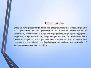
![Surge VS Stall
STALL
LOCAL PHENOMENON
CAUSED BY FLOW SEPARATION
TEMPORARY INSTABILITY
ROTATING IN NATURE
MAY LEAD TO SURGE
MECHANICAL DAMAGE MAY OR
MAY NOT OCCUR
SURGE
GLOBAL PHENOMENON
CAUSED BY FLOW REVERSAL
PERMANENT INSTABILITY
AXIAL IN NATURE
STALL MAY BE THE CAUSE, [TOTAL
FLOW BREAK DOWN]
DAMAGE TO THE COMPRESSOR /
TURBNE INESCAPABLE](https://image.slidesharecdn.com/surge-140915125420-phpapp02/85/Surge-in-compressor-31-320.jpg)


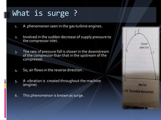
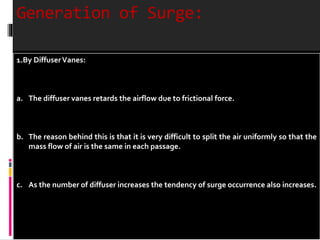
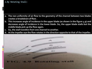
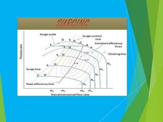
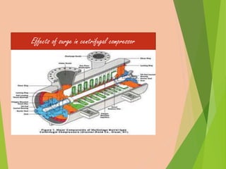
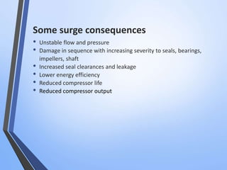
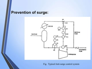
Surge is a phenomenon seen in gas turbine engines where there is a sudden decrease in the supply pressure to the compressor inlet. This causes air to flow in the reverse direction through the compressor, creating vibrations throughout the engine. Surge can be generated by diffuser vanes retarding the airflow or rotating stall causing breakdowns of the air flow between compressor blades. Repeated surging can damage components like rotor seals, bearings, and the compressor driver through high vibrations and temperature increases. Anti-surge systems aim to prevent surge by maintaining a minimum air flow through the compressor.