Downloaded 40 times


The document discusses various types of physical layer ports in computer hardware, which serve as interfaces for connecting computers to peripheral devices. It details different port types, including USB, VGA, HDMI, and FireWire, along with their functionalities and signal transfer methods. Additionally, it covers standardization efforts and color coding associated with ports on personal computers.
Overview of physical layer ports, their types (USB, VGA, etc.), electrical signal transfer, and characteristics of connectors like hot-swapping and plug-and-play.
DVI and DisplayPort as digital video interfaces, their features, and advantages such as backward compatibility and packetized data transmission.
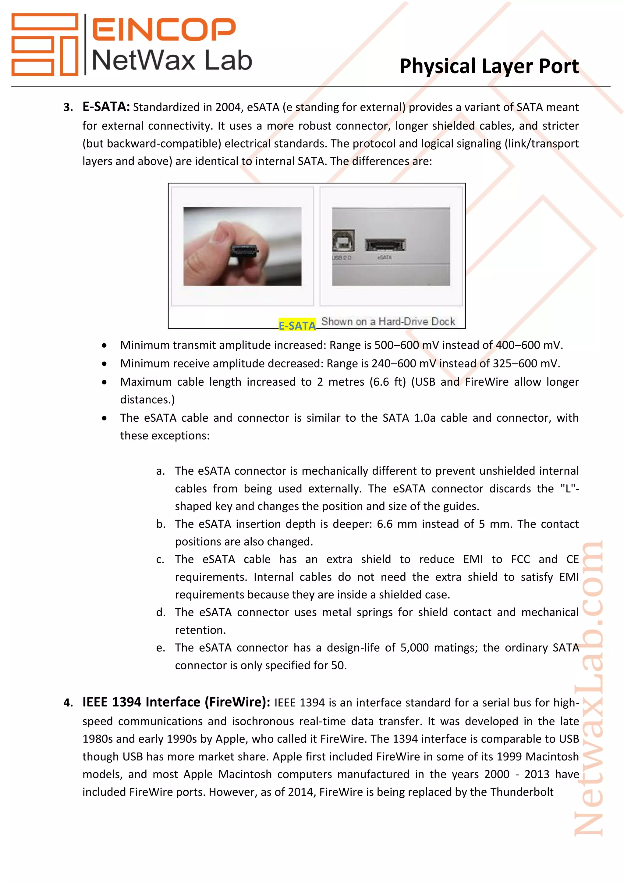
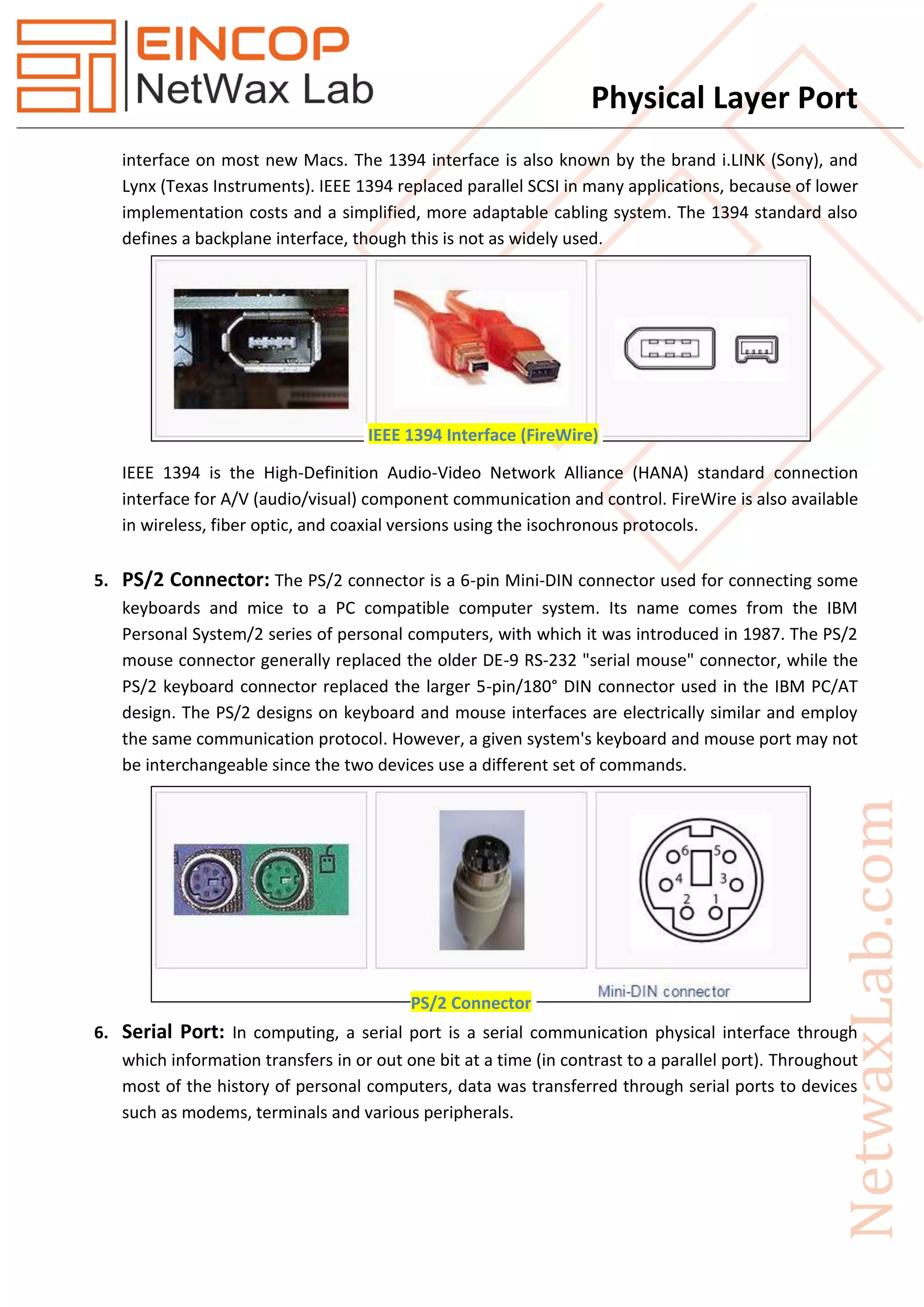
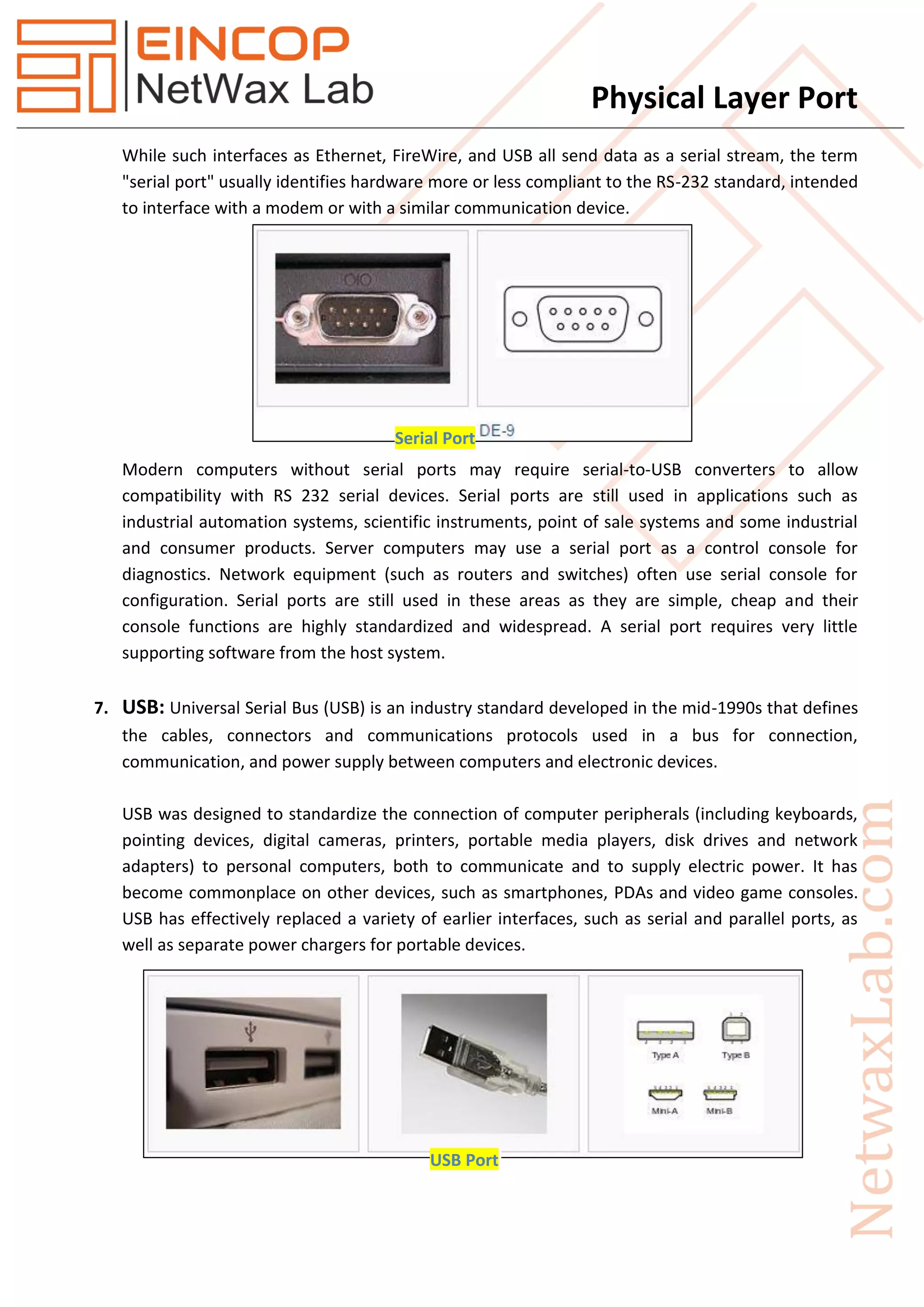
Discussion on eSATA and IEEE 1394 (FireWire) interfaces, their application history, and the relevance of PS/2 and serial ports in computing.
Details on USB standards, its importance for connecting peripherals and power supply, and its replacement of older interfaces.
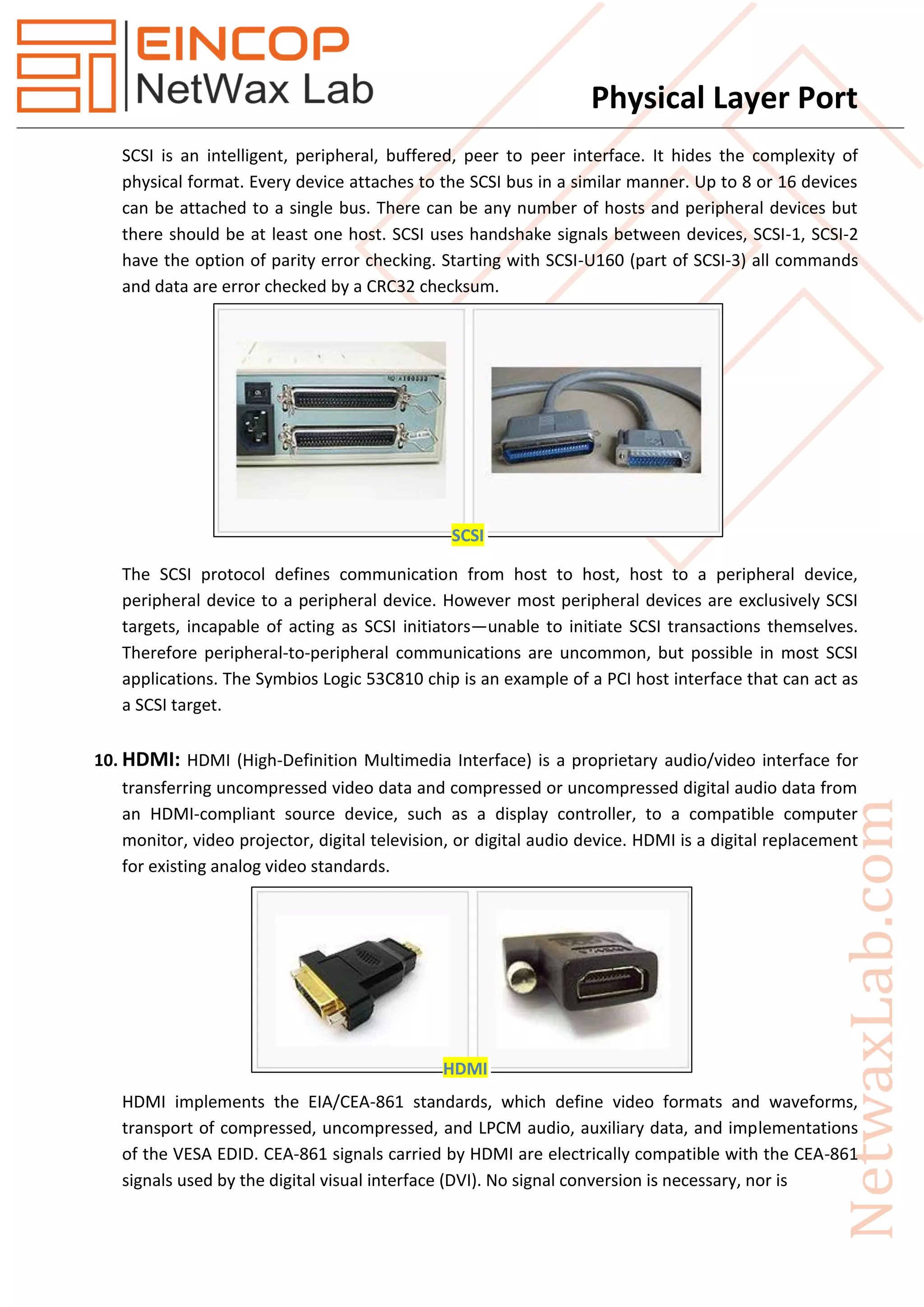
Information on VGA and SCSI connectors, their features, data transfer capabilities, and the introduction of HDMI technology for audio/video transmission.
Description of phone/audio connectors and their historical significance in carrying analog audio signals.