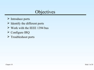
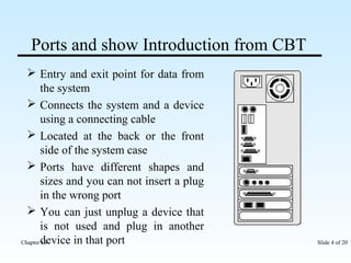
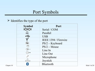
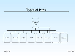
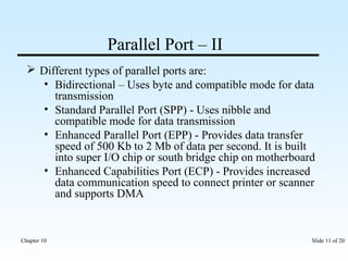
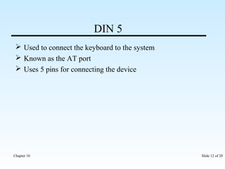
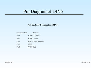
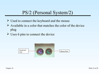
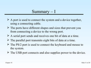
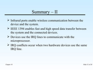
GOHEL VISHAL. H 
LECTURER OF COMPUTER DEPT. 
GOVERNMENT POLYTECHNIC BHUJ 
9638893297 
Chapter 10 Slide 1 of 20
I/O Ports and Devices 
Chapter 10
Objectives 
 Introduce ports 
 Identify the different ports 
 Work with the IEEE 1394 bus 
 Configure IRQ 
 Troubleshoot ports 
Chapter 10 Slide 3 of 20
Ports and show Introduction from CBT 
 Entry and exit point for data from 
the system 
 Connects the system and a device 
using a connecting cable 
 Located at the back or the front 
side of the system case 
 Ports have different shapes and 
sizes and you can not insert a plug 
in the wrong port 
 You can just unplug a device that 
is not used and plug in another 
device in that port 
Chapter 10 Slide 4 of 20
Port Symbols 
 Identifies the type of the port 
Symbol Port 
Serial / COM 
Parallel 
USB 
IEEE 1394 / Firewire 
PS/2 – Keyboard 
PS/2 – Mouse 
Line In 
Line Out 
Microphone 
Joystick 
Bluetooth 
Chapter 10 Slide 5 of 20
Types of Ports 
Types of 
Ports 
Serial Parallel DIN5 PS/2 Infrared Bluetooth USB Firewire 
Chapter 10 Slide 6 of 20
Types of Ports 
Chapter 10 Slide 7 of 20
Serial Port and show through CBT 
 Sends and receives one bit of data at a time 
 Known as the Communication or COM port 
 Has 9 or 25 pins 
 Connect devices such as the mouse, plotters and modems 
 Transmitting device sends a start bit then actual data byte 
followed by a stop bit 
 Maximum cable length is 50 feet 
 If you need more serial ports, you can install multi I/O 
card 
Chapter 10 Slide 8 of 20
Parallel Port – I 
 Transmits eight bits of data at a time 
 Has 25 pins 
 Connects devices such as printers, scanners, external hard 
drive and tape drive 
 You can get more parallel ports by installing an expansion 
card 
 LPT1 uses IRQ7 and LPT2 uses IRQ5 
Chapter 10 Slide 9 of 20
IEEE 1284 
Compatibility Mode – used for directing data from 
computer to peripheral (output only) 
Nibble Mode – 4 bit (Input only) 
Byte Mode – uses software drivers same as nibble 
mode (8 bit) 
Enhanced Parallel Port Mode (EPP) – it is 
hardware driven and bi-directional, high speed 
parallel port interface 
Enhanced Capability Port Mode (ECP) – same as 
EPP uses DMA 
Chapter 10 Slide 10 of 20
Parallel Port – II 
 Different types of parallel ports are: 
• Bidirectional – Uses byte and compatible mode for data 
transmission 
• Standard Parallel Port (SPP) - Uses nibble and 
compatible mode for data transmission 
• Enhanced Parallel Port (EPP) - Provides data transfer 
speed of 500 Kb to 2 Mb of data per second. It is built 
into super I/O chip or south bridge chip on motherboard 
• Enhanced Capabilities Port (ECP) - Provides increased 
data communication speed to connect printer or scanner 
and supports DMA 
Chapter 10 Slide 11 of 20
DIN 5 
 Used to connect the keyboard to the system 
 Known as the AT port 
 Uses 5 pins for connecting the device 
Chapter 10 Slide 12 of 20
Pin Diagram of DIN5 
AT keyboard connector (DIN5) 
Connector Pin # Purpose 
Pin 1 KBDCLK (clock) 
Pin 2 KBDAT (data) 
Pin 3 KBRST (reset, not used) 
Pin 4 GND 
Pin 5 VCC (+5V) 
Chapter 10 Slide 13 of 20
PS/2 (Personal System/2) 
 Used to connect the keyboard and the mouse 
 Available in a color that matches the color of the device 
plug 
 Uses 6 pins to connect the device 
Mouse Port 
Keyboard 
Port 
Chapter 10 Slide 14 of 20
Pin Diagram of PS/2 
PS/2 keyboard connector (MINI-DIN6) 
Connector Pin # Purpose 
Pin 1 KBDAT (data) 
Pin 2 not used 
Pin 3 GND 
Pin 4 VCC (+5V) 
Pin 5 KBDCLK (clock) 
Pin 6 not used 
Chapter 10 Slide 15 of 20
Universal Serial Bus (USB) 
 Connects upto 127 devices to a single port 
 Supplies power to the device 
 Plug-and-play support 
 Maximum cable length is 30m thus you can connect 5 
hubs to the USB 
 Has two different connections: connection A and 
connection B 
 USB 1.0 – 1.5 Mbps, USB 1.1 – 12 Mbps and USB 2.0 – 
480 Mbps 
Chapter 10 Slide 16 of 20
USB Pin Diagram & Configuration 
Chapter 10 Slide 17 of 20
Infrared Ports 
 Communicate with the system without using wires 
 Devices send out infrared signals that enter the system 
through this port 
Infrared Port 
Chapter 10 Slide 18 of 20
Bluetooth Port 
 Allows wireless communication between devices within a 
ranged distance 
 Uses 2.45 GHz frequency range for data communication 
 A Bluetooth adapter required for the computer and a 
Bluetooth compatible device to communicate 
 Speed is 1 or 2 Mbps depending on the version 
Chapter 10 Slide 19 of 20
IEEE 1394 Bus 
 Enables fast and high serial data transfer rate of upto 400 
Mb per second 
 Connects and supplies power to the connected devices 
such as printer, scanner, web camera and generally used 
for transferring audio and video data from a camera to the 
system 
 Known as FireWire by Apple and iLink by Sony 
Chapter 10 Slide 20 of 20
S-Video Port 
 Short for Super-Video, a 
technology for transmitting 
video signals over a cable by 
dividing the video information 
into two separate signals: one 
for color (chrominance), and 
the other for brightness 
(luminance). When sent to a 
television, this produces 
sharper images than composite 
video, where the video 
information is transmitted as a 
single signal over one wire. 
This is because televisions are 
designed to display separate 
Luminance (Y) and 
Chrominance (C) signals. (The 
terms Y/C video and S-Video 
are the same.) 
Chapter 10 Slide 21 of 20
DVI Monitor Port 
 Short for Digital Visual 
Interface, in this case data is 
transmitted using the transition 
minimized differential signaling 
(TMDS) protocol, providing a 
digital signal from the PC's 
graphics subsystem to the 
display. The standard specifies 
a single plug and connector that 
encompass both the new digital 
and legacy VGA interfaces, as 
well as a digital-only plug 
connector. DVI handles 
bandwidths in excess of 160 
MHz and thus supports UXGA 
and HDTV with a single set of 
links. 
Chapter 10 Slide 22 of 20
eSATA 
 Benefits of eSATA: 
• Up to 6 times faster than 
existing external storage 
solutions: USB 2.0, & 1394 
• Robust and user friendly 
external connection 
• High performance, cost 
effective expansion storage 
• Up to 2 meter shielded 
cables and connectors 
• Applications: External 
Direct Attached Storage for 
notebooks, desktop, 
consumer electronics and 
entry servers. 
Chapter 10 Slide 23 of 20
Interrupt Request (IRQ) - I 
Used by devices to communicate with the 
microprocessor 
IRQ 
Number 
Typical Use 
0 System timer 
1 Keyboard 
2 Interrupt for IRQs 8-15 
3 Second serial port (COM2) 
4 First serial port (COM1) 
5 Sound card 
Chapter 10 Slide 24 of 20
Interrupt Request (IRQ) - II 
6 Floppy disk controller 
7 First parallel port. Used by the printer or any 
device using the parallel port. 
8 Real-time clock 
9 Open interrupt 
10 Open interrupt 
11 Open interrupt 
12 PS/2 mouse / Network Card 
13 Floating point unit/coprocessor. Only used for 
internal signaling. 
14 Primary IDE channel 
15 Secondary IDE channel 
Chapter 10 Slide 25 of 20
Show Configuring IRQ from CBT and show it 
practically 
Chapter 10 Slide 26 of 20
6 Channel Sound Card 
 A new version sound card is 
having 6 channels, which 
support multi speaker output. 
Can be easily installed on 
available PCI slot through 
PCI interface. Different 
manufacturers have different 
features for 6 channel sound 
card. Some of them support 
the features such as Direct 
sound 3D and DSL based 
Wavetable music synthesizer 
and 3D positional audio. It 
also contains a game port 
which supports 3D surround 
effect in games. 
Chapter 10 Slide 27 of 20
Wireless LAN USB Adapter 
 Connects computer to wireless LAN 
 By using this adapter desktop, notebook and laptop users 
can connect to a standard mobile network 
 Plugged to computer through a USB port 
 Data Transfer Rate is 54 Mbps 
Chapter 10 Slide 28 of 20
Troubleshooting and show how to resolve IRQ 
conflict practically 
While using the device, errors may occur if there 
is a problem with the I/O port 
Different types of problems related with IO port: 
• Device not working properly 
• IRQ conflicts 
Chapter 10 Slide 29 of 20
Serial or Parallel Cable Testing 
 Cable tester is used to 
verify the connections of 
the cables connected to 
the computer. It is an 
electronic device, which is 
used to check the 
connections in the cable. 
Consists of a current 
source, voltmeter and a 
switching matrix. All the 
contact points in the cable 
are connected to a source 
of current and a voltmeter 
using a switching matrix. 
Chapter 10 Slide 30 of 20
Summary – I 
 A port is used to connect the system and a device together, 
using a connecting cable. 
 The ports have different shapes and sizes that prevent you 
from connecting a device to the wrong port. 
 A serial port sends and receives one bit of data at a time. 
 The parallel port transmits eight bits of data at a time. 
 The PS/2 port is used to connect the keyboard and mouse to 
the system. 
 The USB port connects and also supplies power to the device. 
Chapter 10 Slide 31 of 20
Summary – II 
 Infrared ports enable wireless communication between the 
device and the system. 
 IEEE 1394 enables fast and high speed data transfer between 
the system and the connected devices. 
 Devices use the IRQ lines to communicate with the 
microprocessor. 
 IRQ conflicts occur when two hardware devices use the same 
IRQ line. 
Chapter 10 Slide 32 of 20

I/O DECIVES CPU

  • 1.
    GOHEL VISHAL. H LECTURER OF COMPUTER DEPT. GOVERNMENT POLYTECHNIC BHUJ 9638893297 Chapter 10 Slide 1 of 20
  • 2.
    I/O Ports andDevices Chapter 10
  • 3.
    Objectives  Introduceports  Identify the different ports  Work with the IEEE 1394 bus  Configure IRQ  Troubleshoot ports Chapter 10 Slide 3 of 20
  • 4.
    Ports and showIntroduction from CBT  Entry and exit point for data from the system  Connects the system and a device using a connecting cable  Located at the back or the front side of the system case  Ports have different shapes and sizes and you can not insert a plug in the wrong port  You can just unplug a device that is not used and plug in another device in that port Chapter 10 Slide 4 of 20
  • 5.
    Port Symbols Identifies the type of the port Symbol Port Serial / COM Parallel USB IEEE 1394 / Firewire PS/2 – Keyboard PS/2 – Mouse Line In Line Out Microphone Joystick Bluetooth Chapter 10 Slide 5 of 20
  • 6.
    Types of Ports Types of Ports Serial Parallel DIN5 PS/2 Infrared Bluetooth USB Firewire Chapter 10 Slide 6 of 20
  • 7.
    Types of Ports Chapter 10 Slide 7 of 20
  • 8.
    Serial Port andshow through CBT  Sends and receives one bit of data at a time  Known as the Communication or COM port  Has 9 or 25 pins  Connect devices such as the mouse, plotters and modems  Transmitting device sends a start bit then actual data byte followed by a stop bit  Maximum cable length is 50 feet  If you need more serial ports, you can install multi I/O card Chapter 10 Slide 8 of 20
  • 9.
    Parallel Port –I  Transmits eight bits of data at a time  Has 25 pins  Connects devices such as printers, scanners, external hard drive and tape drive  You can get more parallel ports by installing an expansion card  LPT1 uses IRQ7 and LPT2 uses IRQ5 Chapter 10 Slide 9 of 20
  • 10.
    IEEE 1284 CompatibilityMode – used for directing data from computer to peripheral (output only) Nibble Mode – 4 bit (Input only) Byte Mode – uses software drivers same as nibble mode (8 bit) Enhanced Parallel Port Mode (EPP) – it is hardware driven and bi-directional, high speed parallel port interface Enhanced Capability Port Mode (ECP) – same as EPP uses DMA Chapter 10 Slide 10 of 20
  • 11.
    Parallel Port –II  Different types of parallel ports are: • Bidirectional – Uses byte and compatible mode for data transmission • Standard Parallel Port (SPP) - Uses nibble and compatible mode for data transmission • Enhanced Parallel Port (EPP) - Provides data transfer speed of 500 Kb to 2 Mb of data per second. It is built into super I/O chip or south bridge chip on motherboard • Enhanced Capabilities Port (ECP) - Provides increased data communication speed to connect printer or scanner and supports DMA Chapter 10 Slide 11 of 20
  • 12.
    DIN 5 Used to connect the keyboard to the system  Known as the AT port  Uses 5 pins for connecting the device Chapter 10 Slide 12 of 20
  • 13.
    Pin Diagram ofDIN5 AT keyboard connector (DIN5) Connector Pin # Purpose Pin 1 KBDCLK (clock) Pin 2 KBDAT (data) Pin 3 KBRST (reset, not used) Pin 4 GND Pin 5 VCC (+5V) Chapter 10 Slide 13 of 20
  • 14.
    PS/2 (Personal System/2)  Used to connect the keyboard and the mouse  Available in a color that matches the color of the device plug  Uses 6 pins to connect the device Mouse Port Keyboard Port Chapter 10 Slide 14 of 20
  • 15.
    Pin Diagram ofPS/2 PS/2 keyboard connector (MINI-DIN6) Connector Pin # Purpose Pin 1 KBDAT (data) Pin 2 not used Pin 3 GND Pin 4 VCC (+5V) Pin 5 KBDCLK (clock) Pin 6 not used Chapter 10 Slide 15 of 20
  • 16.
    Universal Serial Bus(USB)  Connects upto 127 devices to a single port  Supplies power to the device  Plug-and-play support  Maximum cable length is 30m thus you can connect 5 hubs to the USB  Has two different connections: connection A and connection B  USB 1.0 – 1.5 Mbps, USB 1.1 – 12 Mbps and USB 2.0 – 480 Mbps Chapter 10 Slide 16 of 20
  • 17.
    USB Pin Diagram& Configuration Chapter 10 Slide 17 of 20
  • 18.
    Infrared Ports Communicate with the system without using wires  Devices send out infrared signals that enter the system through this port Infrared Port Chapter 10 Slide 18 of 20
  • 19.
    Bluetooth Port Allows wireless communication between devices within a ranged distance  Uses 2.45 GHz frequency range for data communication  A Bluetooth adapter required for the computer and a Bluetooth compatible device to communicate  Speed is 1 or 2 Mbps depending on the version Chapter 10 Slide 19 of 20
  • 20.
    IEEE 1394 Bus  Enables fast and high serial data transfer rate of upto 400 Mb per second  Connects and supplies power to the connected devices such as printer, scanner, web camera and generally used for transferring audio and video data from a camera to the system  Known as FireWire by Apple and iLink by Sony Chapter 10 Slide 20 of 20
  • 21.
    S-Video Port Short for Super-Video, a technology for transmitting video signals over a cable by dividing the video information into two separate signals: one for color (chrominance), and the other for brightness (luminance). When sent to a television, this produces sharper images than composite video, where the video information is transmitted as a single signal over one wire. This is because televisions are designed to display separate Luminance (Y) and Chrominance (C) signals. (The terms Y/C video and S-Video are the same.) Chapter 10 Slide 21 of 20
  • 22.
    DVI Monitor Port  Short for Digital Visual Interface, in this case data is transmitted using the transition minimized differential signaling (TMDS) protocol, providing a digital signal from the PC's graphics subsystem to the display. The standard specifies a single plug and connector that encompass both the new digital and legacy VGA interfaces, as well as a digital-only plug connector. DVI handles bandwidths in excess of 160 MHz and thus supports UXGA and HDTV with a single set of links. Chapter 10 Slide 22 of 20
  • 23.
    eSATA  Benefitsof eSATA: • Up to 6 times faster than existing external storage solutions: USB 2.0, & 1394 • Robust and user friendly external connection • High performance, cost effective expansion storage • Up to 2 meter shielded cables and connectors • Applications: External Direct Attached Storage for notebooks, desktop, consumer electronics and entry servers. Chapter 10 Slide 23 of 20
  • 24.
    Interrupt Request (IRQ)- I Used by devices to communicate with the microprocessor IRQ Number Typical Use 0 System timer 1 Keyboard 2 Interrupt for IRQs 8-15 3 Second serial port (COM2) 4 First serial port (COM1) 5 Sound card Chapter 10 Slide 24 of 20
  • 25.
    Interrupt Request (IRQ)- II 6 Floppy disk controller 7 First parallel port. Used by the printer or any device using the parallel port. 8 Real-time clock 9 Open interrupt 10 Open interrupt 11 Open interrupt 12 PS/2 mouse / Network Card 13 Floating point unit/coprocessor. Only used for internal signaling. 14 Primary IDE channel 15 Secondary IDE channel Chapter 10 Slide 25 of 20
  • 26.
    Show Configuring IRQfrom CBT and show it practically Chapter 10 Slide 26 of 20
  • 27.
    6 Channel SoundCard  A new version sound card is having 6 channels, which support multi speaker output. Can be easily installed on available PCI slot through PCI interface. Different manufacturers have different features for 6 channel sound card. Some of them support the features such as Direct sound 3D and DSL based Wavetable music synthesizer and 3D positional audio. It also contains a game port which supports 3D surround effect in games. Chapter 10 Slide 27 of 20
  • 28.
    Wireless LAN USBAdapter  Connects computer to wireless LAN  By using this adapter desktop, notebook and laptop users can connect to a standard mobile network  Plugged to computer through a USB port  Data Transfer Rate is 54 Mbps Chapter 10 Slide 28 of 20
  • 29.
    Troubleshooting and showhow to resolve IRQ conflict practically While using the device, errors may occur if there is a problem with the I/O port Different types of problems related with IO port: • Device not working properly • IRQ conflicts Chapter 10 Slide 29 of 20
  • 30.
    Serial or ParallelCable Testing  Cable tester is used to verify the connections of the cables connected to the computer. It is an electronic device, which is used to check the connections in the cable. Consists of a current source, voltmeter and a switching matrix. All the contact points in the cable are connected to a source of current and a voltmeter using a switching matrix. Chapter 10 Slide 30 of 20
  • 31.
    Summary – I  A port is used to connect the system and a device together, using a connecting cable.  The ports have different shapes and sizes that prevent you from connecting a device to the wrong port.  A serial port sends and receives one bit of data at a time.  The parallel port transmits eight bits of data at a time.  The PS/2 port is used to connect the keyboard and mouse to the system.  The USB port connects and also supplies power to the device. Chapter 10 Slide 31 of 20
  • 32.
    Summary – II  Infrared ports enable wireless communication between the device and the system.  IEEE 1394 enables fast and high speed data transfer between the system and the connected devices.  Devices use the IRQ lines to communicate with the microprocessor.  IRQ conflicts occur when two hardware devices use the same IRQ line. Chapter 10 Slide 32 of 20