Downloaded 121 times

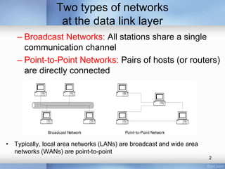

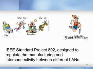
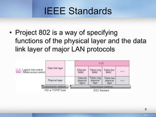
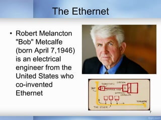
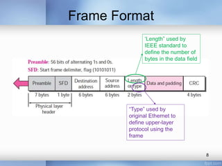
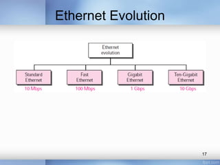
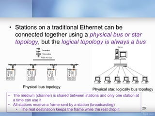


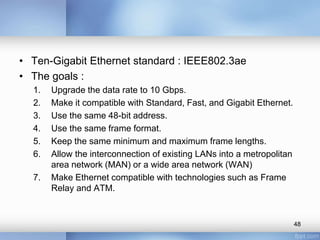
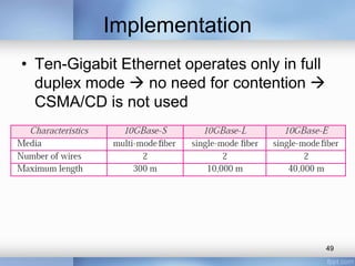

- The document discusses different types of computer networks at the data link layer, including broadcast networks where all stations share a channel and point-to-point networks where pairs of hosts are directly connected. It focuses on wired local area networks (LANs). - Common LAN technologies discussed include Ethernet, Token Ring, FDDI, and ATM LAN. Ethernet standards including Fast Ethernet and Gigabit Ethernet are explained in detail, covering their goals, frame formats, addressing, and implementations of half-duplex and full-duplex modes. - Ten-Gigabit Ethernet is also summarized, with the goals of upgrading the data rate to 10Gbps while maintaining compatibility with previous Ethernet standards.