Downloaded 558 times


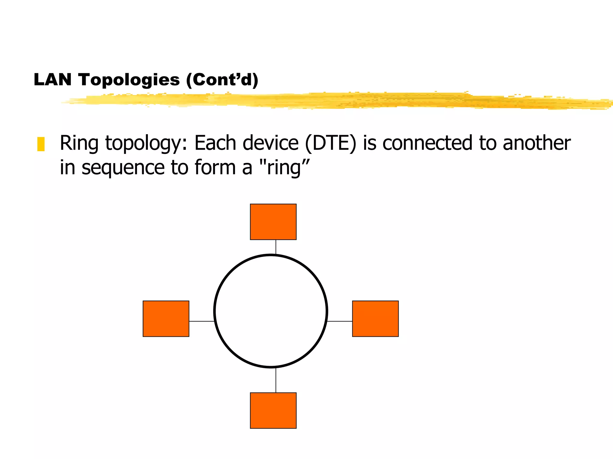


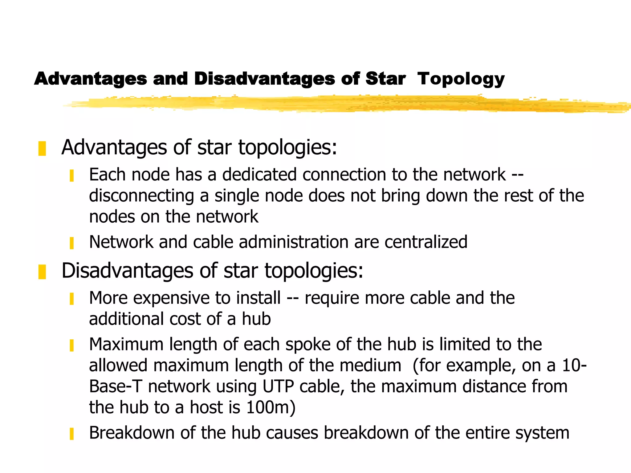
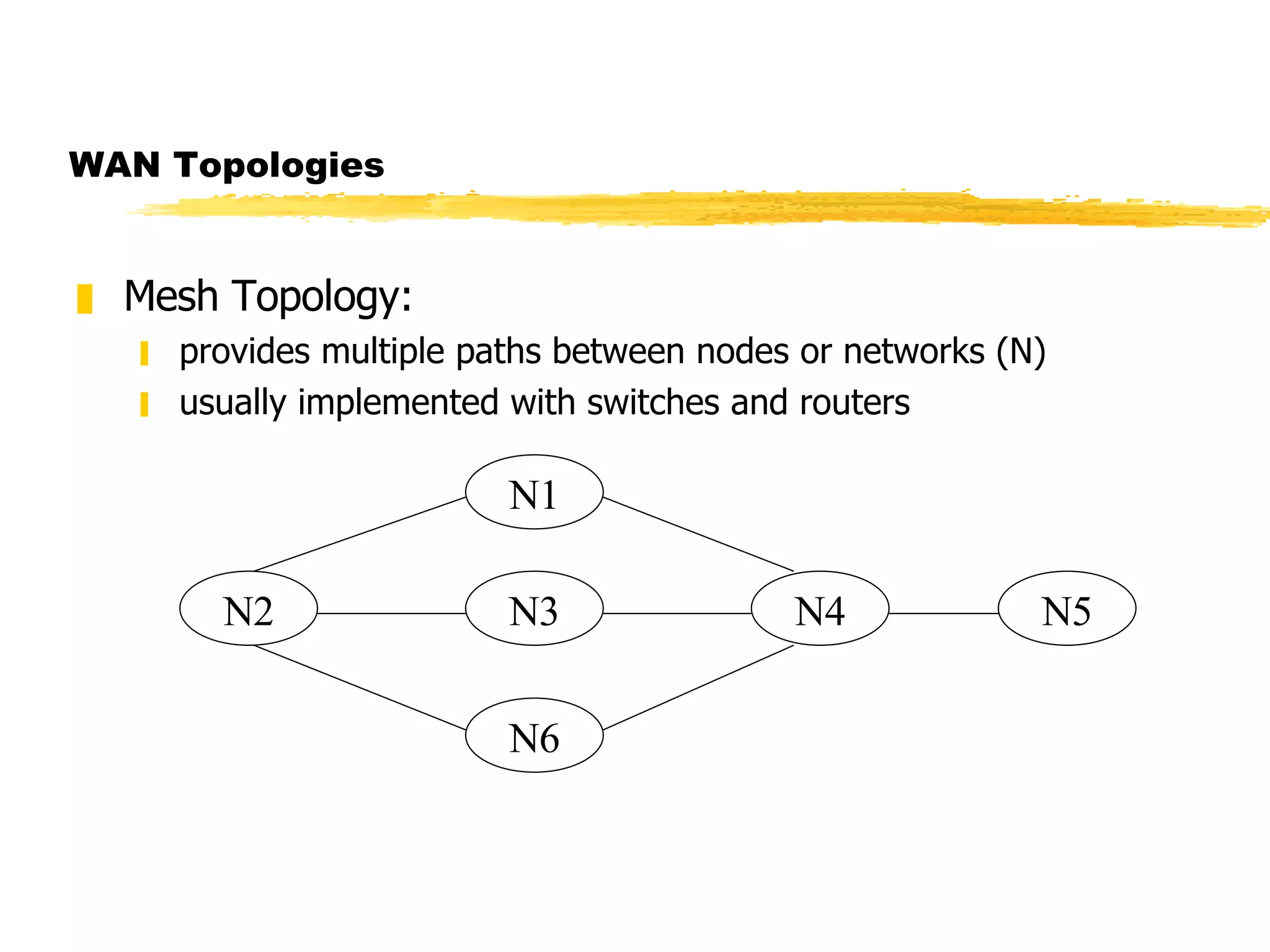
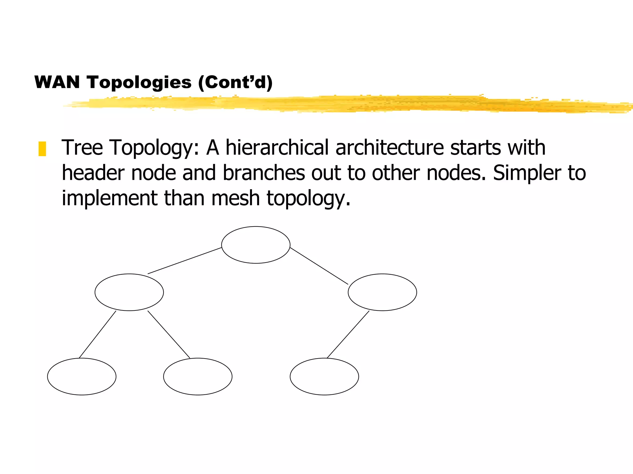


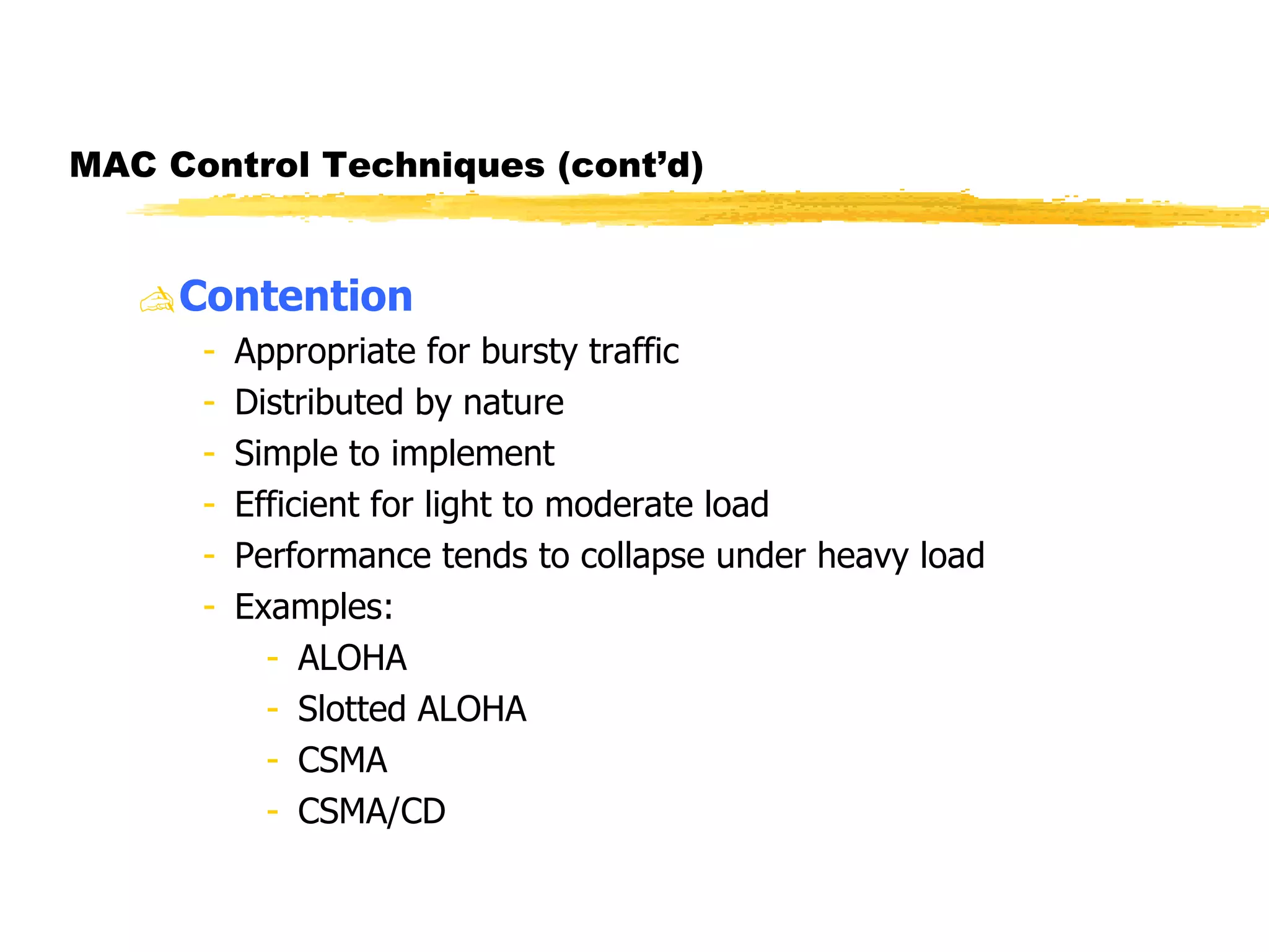


The document discusses different network topologies including LAN and WAN topologies. It describes common LAN topologies like bus, ring, and star as well as WAN topologies like mesh and tree. It also discusses the data link layer and media access control protocols like CSMA/CD that are used to allow devices to share the transmission medium in a LAN.