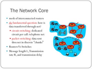
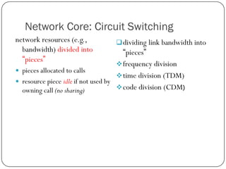
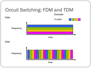
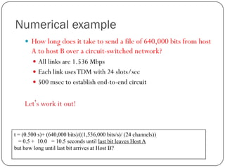
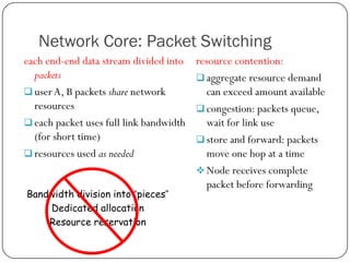
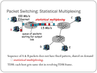
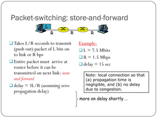
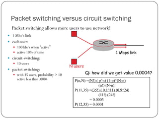
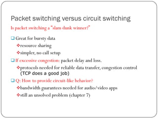
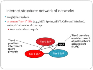
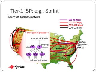
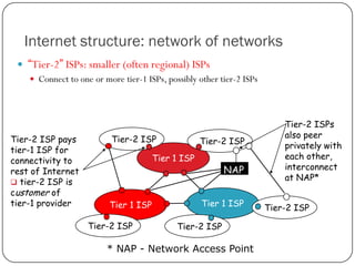
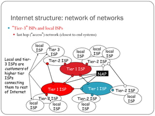
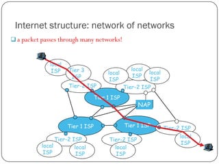
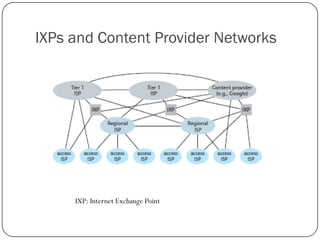
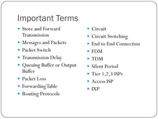
2. Important Terms Review
DSL
LAN
DSLAM
3G
HFC
LTE
CMTS
WiFi
FTTH
Physical Medium Types
AON
UTP
PON
Shared Medium
ONT
OC (Optical Carrier)
OLT
Geostationary Satellite
LEO Satellite
3. The Network Core
mesh of interconnected routers
the fundamental question: how is
data transferred through net?
circuit switching: dedicated
circuit per call: telephone net
packet-switching: data sent
thru net in discrete “chunks”
Routers Vs Switches
Message length L, Transmission
rate R, and transmission delay
4. Network Core: Circuit Switching
network resources (e.g.,
bandwidth) divided into
“pieces”
dividing link bandwidth into
“pieces”
frequency division
pieces allocated to calls
time division (TDM)
resource piece idle if not used by
code division (CDM)
owning call (no sharing)
6. Numerical example
How long does it take to send a file of 640,000 bits from host
A to host B over a circuit-switched network?
All links are 1.536 Mbps
Each link uses TDM with 24 slots/sec
500 msec to establish end-to-end circuit
Let’s work it out!
t = (0.500 s)+ (640,000 bits)/((1,536,000 bits/s)/ (24 channels))
= 0.5 + 10.0 = 10.5 seconds until last bit leaves Host A
but how long until last bit arrives at Host B?
7. Network Core: Packet Switching
each end-end data stream divided into
packets
user A, B packets share network
resources
each packet uses full link bandwidth
(for short time)
resources used as needed
Bandwidth division into “pieces”
Dedicated allocation
Resource reservation
resource contention:
aggregate resource demand
can exceed amount available
congestion: packets queue,
wait for link use
store and forward: packets
move one hop at a time
Node receives complete
packet before forwarding
8. Packet Switching: Statistical Multiplexing
100 Mb/s
Ethernet
A
B
C
statistical multiplexing
1.5 Mb/s
queue of packets
waiting for output
link
D
E
Sequence of A & B packets does not have fixed pattern, shared on demand
statistical multiplexing.
TDM: each host gets same slot in revolving TDM frame.
9. Packet-switching: store-and-forward
L
R
R
Takes L/R seconds to transmit
(push out) packet of L bits on
to link or R bps
Entire packet must arrive at
router before it can be
transmitted on next link: store
and forward
delay = 3L/R (assuming zero
propagation delay)
R
Example:
L = 7.5 Mbits
R = 1.5 Mbps
delay = 15 sec
Note: local connection so that
(a) propagation time is
negligible, and (b) no delay
due to congestion.
more on delay shortly …
10. Packet switching versus circuit switching
Packet switching allows more users to use network!
1 Mb/s link
each user:
100 kb/s when “active”
active 10% of time
1 Mbps link
circuit-switching:
10 users
packet switching:
with 35 users, probability > 10
active less than .0004
N users
Q: how did we get value 0.0004?
P(n,N) =(N!) ( p^n) (1-p)^(N-n)
(n!) (N-n)!
P(11,35) =(35!) ( 0.1^11) (0.9^24)
(11!) (24!)
= 0.0003
P(12,35) = 0.0001
11. Packet switching versus circuit switching
Is packet switching a “slam dunk winner?”
Great for bursty data
resource sharing
simpler, no call setup
If excessive congestion: packet delay and loss.
protocols needed for reliable data transfer, congestion control
(TCP does a good job)
Q: How to provide circuit-like behavior?
bandwidth guarantees needed for audio/video apps
still an unsolved problem (chapter 7)
12. Internet structure: network of networks
roughly hierarchical
at center: “tier-1” ISPs (e.g., MCI, Sprint, AT&T, Cable and Wireless),
national/international coverage
treat each other as equals
Tier-1
providers
interconnect
(peer)
privately
Tier 1 ISP
Tier 1 ISP
NAP
Tier 1 ISP
Tier-1 providers
also interconnect
at public network
access points
(NAPs)
13. Tier-1 ISP: e.g., Sprint
Sprint US backbone network
Seattle
Tacoma
DS3 (45 Mbps)
OC3 (155 Mbps)
OC12 (622 Mbps)
OC48 (2.4 Gbps)
POP: point-of-presence
to/from backbone
Stockton
peering
…
…
.
Kansas City
…
…
Anaheim
…
San Jose
Cheyenne
New York
Pennsauken
Relay
Wash. DC
Chicago
Roachdale
Atlanta
to/from customers
Fort Worth
Introduction
Orlando
14. Internet structure: network of networks
“Tier-2” ISPs: smaller (often regional) ISPs
Connect to one or more tier-1 ISPs, possibly other tier-2 ISPs
Tier-2 ISP pays
tier-1 ISP for
connectivity to
rest of Internet
tier-2 ISP is
customer of
tier-1 provider
Tier-2 ISP
Tier-2 ISP
Tier 1 ISP
Tier 1 ISP
Tier-2 ISP
NAP
Tier 1 ISP
Tier-2 ISP
* NAP - Network Access Point
Tier-2 ISPs
also peer
privately with
each other,
interconnect
at NAP*
Tier-2 ISP
15. Internet structure: network of networks
“Tier-3” ISPs and local ISPs
last hop (“access”) network (closest to end systems)
local
ISP
Local and tier3 ISPs are
customers of
higher tier
ISPs
connecting
them to rest
of Internet
Tier 3
ISP
Tier-2 ISP
local
ISP
local
ISP
local
ISP
Tier-2 ISP
Tier 1 ISP
Tier 1 ISP
Tier-2 ISP
local
local
ISP
ISP
NAP
Tier 1 ISP
Tier-2 ISP
local
ISP
Tier-2 ISP
local
ISP
16. Internet structure: network of networks
a packet passes through many networks!
local
ISP
Tier 3
ISP
Tier-2 ISP
local
ISP
local
ISP
local
ISP
Tier-2 ISP
Tier 1 ISP
Tier 1 ISP
Tier-2 ISP
local
local
ISP
ISP
NAP
Tier 1 ISP
Tier-2 ISP
local
ISP
Tier-2 ISP
local
ISP