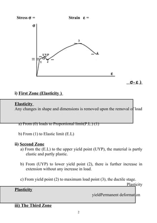
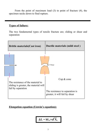
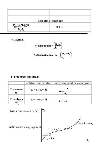
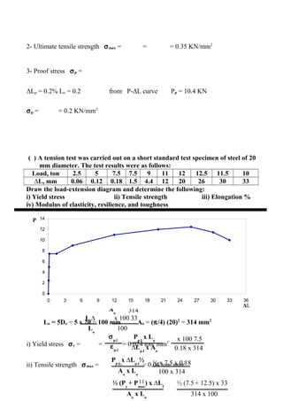
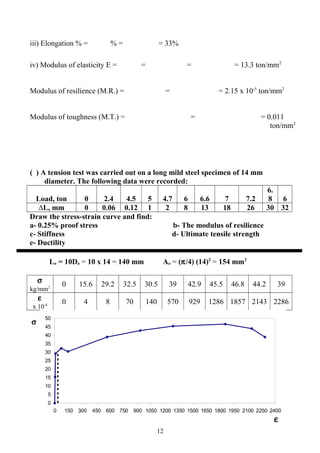
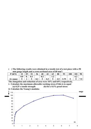
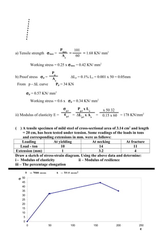
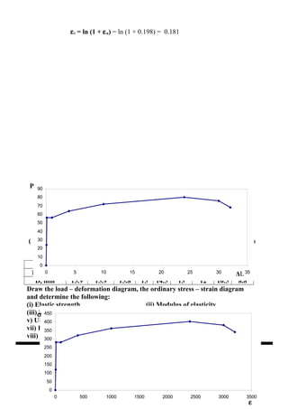
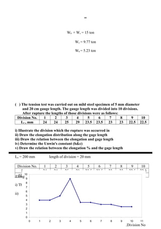
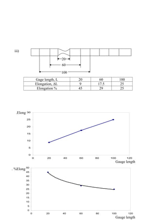
P
Aо
∆L
Lo
Tension Test
♦
♦
Brittle materials
1- Cast iron 2- Concrete
Brittleness:
deformation
Ductile materials
Steel&Al
Ductility:
The ability of the material to be
drawn under tensile load without
fracture
ORDINARY STRESS-STRAIN DIAGRAM
1
F
F
F
F
max
max
max
y
y
p.l.
p.l.
p.l.
ε
ε
ε
ε
σ
σ
σ
Stress σ = Strain ε =
)σ- ε
i) First Zone (Elasticity )
Elasticity
Any changes in shape and dimensions is removed upon the removal of load
a) From (0) loads to Proportional limit(P.L.) (1)
b) From (1) to Elastic limit (E.L)
ii) Second Zone
a) From the (E.L) to the upper yield point (UYP), the material is partly
elastic and partly plastic.
b) From (UYP) to lower yield point (2), there is further increase in
extension without any increase in load.
c) From yield point (2) to maximum load point (3), the ductile stage.
Plasticity
Plasticity
Permanent deformationyield
iii) The Third Zone
2
3
4
21
UYP
O
σ
ε
From the point of maximum load (3) to point of fracture (4), the
specimen necks down to final rupture.
Types of failure:
The two fundamental types of tensile fracture are; sliding or shear and
separation
Brittle materials(Cast iron) Ductile materials (mild steel )
The resistance of the material to
sliding is greater, the material will
fail by separation
Cup & cone
The resistance to separation is
greater, it will fail by shear
Elongation equation (Unwin’s equation):
∆L = bLо+c Aо
3
Elongation at gage length
(Plastic deformation)
bLо
Max
Necking elongation
c Aо
1-
2Lо
% = b +
neckingnecking
Specimen For circular section Use
Short
Lо= 5.65 Aо
Lо= 5Dо Brittle material
Long
Lо= 11.3 Aо
Lо= 10Dо Ductile material
Strength
The external load required to overcome bonds between atoms
1- Stress at proportional limit
4
∆L
Lо
Lо
elong %
∆L
Lo
c Aо
Lo
Pp.L
Aо
Pmax
Aо
Py
Aо
Pf
Aо
Pp
Aо
σy
F.S
σp
F.S
σp.l
F.S
The stress at the last point of proportionality line between σ,ε
σp.l =
2- Ultimate tensile strength
σmax =
3- Yield stress
σy =
4- Fracture stress
σf =
5- Working stress
σw = or or
6- Proof stress
σp =
working stress
It is the stress which produced under a load of non-proportional
elongation equal to certain specified percentage (0.1 – 0.5%) of the
original gage length
5 ∆Lp
∆L
p
pp
∆Lp
= (0.1 – 0.5)% x Lо
εp.l
σp.l
∆Lp.l
x Aо
Pp.l
x Lо
Lо
Aо
½Pp.l
x ∆Lp.l
7- Stiffness
deformationE
Modulus of elasticity (stiffness) E = =
σ – ε
1- Initial tangent modulus
E1 = tan θ1
2- Secant modulus
E2 = tan θ2
3- Tangent modulus
E3 = tan θ3
8- Resilience
proportional lineP-∆L
R = ½ Pp.l x ∆Lp.l
Modulus of resilience (M.R) =
9- Toughness
Brittle materialsDuctile materials
6
σ
ε
Dо
Di
Lо
Aо
½(Py
+Pmax
)∆Lf
Lо
Aо
⅔Pmax
x ∆Lmax
∆Lf
Lо
Aо
- Af
Aо
Pi
Ai
Modulus of toughness
M.T. =M.T.=
10- Ductility
% Elongation =
%Reduction in area =
11- True stress and strain
At Max. Point or before After Max. point or at any point
True stress
σt
σt = σn(εn + 1)
σt =
True strain
εt
εt = ln (εn + 1)
εt = 2ln
True stress - strain curve
n: Strain hardening exponent
7
%
σt
= k + m εt
σt
= k εt
n
σt
= E εt
σt
εt
∆Di
/Do
∆Li
/Lo
k: Strength coefficient
Prove that σt = σn (εn + 1)
Assume constant volume AоLо = AiLi
σn = σt =
Ai = σt =
σt = x = σn
σt = σn(εn + 1)
12- Poisson ratio
μ =
•Factors affecting tension test
(1) Carbon%
Pp.l & Py
σmax(ton/in2
) = 27.06(1+K2
) K = carbon%
(2) Temperature
8
Lо
Aо
A1 A2
L1 L2
P1
P2
Pi
Aо
Pi
Ai
Aо
Lо
Li
Pi
Li
Aо
Lо
Pi
Aо
Li
Lо
∆L + Lо
Lо
0.15%C
ε
σ
0.6%C
0.8%C
250°Cductilitytensile strengthE
(3) Test speed
ductility
(4) Cross-section shape
(5) Overstrain
Pp.lyield stress
•Yield phenomena
yieldyield
Yield point
P 0 2 4 6
5.
5
7 P 0 2 4 6
6
8
∆L 0 0.02
0.0
4
0.06 1 3 ∆L 0 0.02 0.04 0.06
1
5
•Necking
1neck
245°45°
Hyper-elastic resilience resilience
9
εp.l
σp.l
∆Lp.l
x Aо
Pp.l
x Lо
0.1 x 50.3
10x 100
Pmax
Aо
17.5
50.3
Pp
Aо
10.4
50.4
Resilience Hyper-elastic resilience
Hysteresis
SHEET 1
( ) A tension test was carried out on a steel specimen of 8 mm diameter. The
following data were obtained for the load P in KN and extension ΔL on a
gage length of 100 mm:
P (KN) 0 5 8 10 13 15 16.5 17.5 17 15
∆L (mm) 0 0.05 0.08 0.1 1.5 3.5 6 9 11 15
Draw the load-extension diagram and determines:
(i) Modulus of elasticity (ii) 0.2% proof stress
(iii) Ultimate tensile strength (iv) Draw the fracture shape of the tested specimen
Aо = (π/4) (8)2
= 50.3 mm2
1- Modulus of elasticity E = = = = 198.8 KN/mm2
10
0
2
4
6
8
10
12
14
16
18
20
0 2 4 6 8 10 12 14 16
P
ΔL
Proof point
Pmax
Aо
12.5
314
Py
Aо
7.5
314
∆Lf
Lо
33x 100
100
εp.l
σp.l
∆Lp.l
x Aо
Pp.l
x Lо
0.18 x 314
7.5x 100
Aо
x Lо
½Pp.l
x ∆Lp.l
100 x 314
½ x 7.5 x 0.18
Aо
x Lо
½ (Py
+ Pmax
) x ∆Lf
314 x 100
½ (7.5+ 12.5) x 33
2- Ultimate tensile strength σmax = = = 0.35 KN/mm2
3- Proof stress σp =
ΔLp = 0.2% Lo = 0.2 from P-ΔL curve Pp = 10.4 KN
σp = = 0.2 KN/mm2
( ) A tension test was carried out on a short standard test specimen of steel of 20
mm diameter. The test results were as follows:
Load, ton 2.5 5 7.5 7.5 9 11 12 12.5 11.5 10
∆L, mm 0.06 0.12 0.18 1.5 4.4 12 20 26 30 33
Draw the load-extension diagram and determine the following:
i) Yield stress ii) Tensile strength iii) Elongation %
iv) Modulus of elasticity, resilience, and toughness
Lо = 5Dо = 5 x 20 = 100 mm Aо = (π/4) (20)2
= 314 mm2
i) Yield stress σy = = = 0.024 ton/ mm2
ii) Tensile strength σmax = = = 0.04 ton/ mm2
11
0
2
4
6
8
10
12
14
0 3 6 9 12 15 18 21 24 27 30 33 36
P
ΔL
iii) Elongation % = % = = 33%
iv) Modulus of elasticity E = = = = 13.3 ton/mm2
Modulus of resilience (M.R.) = = = 2.15 x 10⁻⁵
ton/mm2
Modulus of toughness (M.T.) = = = 0.011
ton/mm2
( ) A tension test was carried out on a long mild steel specimen of 14 mm
diameter. The following data were recorded:
Load, ton 0 2.4 4.5 5 4.7 6 6.6 7 7.2
6.
8 6
∆L, mm 0 0.06 0.12 1 2 8 13 18 26 30 32
Draw the stress-strain curve and find:
a- 0.25% proof stress b- The modulus of resilience
c- Stiffness d- Ultimate tensile strength
e- Ductility
Lо = 10Dо = 10 x 14 = 140 mm Aо = (π/4) (14)2
= 154 mm2
σ
kg/mm2
0 15.6 29.2 32.5 30.5 39 42.9 45.5 46.8 44.2 39
ε
x 10-4
0 4 8 70 140 570 929 1286 1857 2143 2286
12
0
5
10
15
20
25
30
35
40
45
50
0 150 300 450 600 750 900 1050 1200 1350 1500 1650 1800 1950 2100 2250 2400
σ
ε
Pp
Aо
Aо
x Lо
½Pp.l
x ∆Lp.l
140 x 154
½ x 4.5 x 0.12
Pmax
Aо
7.2
154
∆Lf
Lо
32x 100
140
εp.l
σp.l
∆Lp.l
x Aо
Pp.l
x Lо
0.12 x 154
4.5x 140
Aо
x Lо
½Pp.l
x ∆Lp.l
140 x 154
½ x 4.5 x 0.12
Pmax
Aо
7.2
154
∆Lf
Lо
32x 100
140
εp.l
σp.l
∆Lp.l
x Aо
Pp.l
x Lо
0.12 x 154
4.5x 140
Py
Aо
4.3
154
Pmax
Aо
7.2
154
ΔL
Lо
26
140
a- Proof stress σp = ΔLp = 0.25% Lo = 0.35mm
ε = 0.35/140 = 25 x 10-4
From σ - ε curve σp = 30 kg/ mm2
b- Modulus of resilience (M.R.) = = = 1.25 x 10⁻⁵
ton/mm2
c- Modulus of elasticity E = = = = 34.1 ton/mm2
d- Tensile strength σmax = = = 0.047 ton/ mm2
e- Elongation % = % = = 23%
( ) A tension test was carried out on a long mild steel specimen of 14 mm
diameter. The following data were recorded:
Load, ton 0 2.4 4.5 4.3 5.1 6 6.6 7 7.2
6.
8 6
∆L, mm 0 0.06 0.12
0.1
5 3 8 13 18 26 30 32
Calculate:
a- The yield stress b- The modulus of resilience
c- Stiffness d- Ultimate tensile strength
e- Ductility f- True stress and true strain at initial necking
Lо = 10Dо = 10 x 14 = 140 mm Aо = (π/4) (14)2
= 154 mm2
a- Yield stress σy = = = 0.028 ton/ mm2
b- Modulus of resilience (M.R.) = = = 1.25 x 10⁻⁵
ton/mm2
c- Modulus of elasticity E = = = = 34.1 ton/mm2
d- Tensile strength σmax = = = 0.047 ton/ mm2
e- Elongation % = % = = 23%
13
f- Initial necking at max. Point
σn = = = 0.047 ton/ mm2
εn = = = 0.186
σt = σn (1 + εn) = 0.047(1 + 0.186) = 0.056 ton/ mm2
εt = ln (1 + εn) = ln (1 + 0.186) = 0.171
( ) A tension test was carried out on a metallic road of 50 mm2
cross-sectional
area, and 100 mm gage length. The load in KN and the corresponding
extension in mm are as follows:
P (KN) 0 5 8 10 13 15 16.5 17.5 17 15
∆L (mm) 0 0.05 0.08 0.1 1.5 3.5 6 9 11 15
Draw nominal stress-strain diagrams and determine the following:
(i) 0.2% proof stress (ii) Modulus of elasticity
(iii) Tensile strength (iv) Elongation percent
v) Modulus of toughness
Lо = 100 mm Aо = 50 mm2
σ (N/mm2
0 100 160 200 260 300 330 350 340 300
ε (x 10-4
) 0 5 8 10 150 350 600 900
110
0 1500
14
0
50
100
150
200
250
300
350
400
0 150 300 450 600 750 900 1050 1200 1350 1500
σ
ε
Pp
Aо
Pmax
Aо
17.5
50
∆Lf
Lо
15x 100
100
εp.l
σp.l
∆Lp.l
x Aо
Pp.l
x Lо
0.1 x 50
10x 100
Aо
x Lо
½ (Py
+ Pmax
) x ∆Lf
50 x 100
½ (10.5+ 17.5) x 15
Pmax
Aо
1.75
50
εp.l
σp.l
∆Lp.l
x Aо
Pp.l
x Lо
0.1 x 50
1x 100
Aо
x Lо
½ (Py
+ Pmax
) x ∆Lf
50 x 100
½ (1+ 1.75) x 15
∆Lf
Lо
15x 100
100
i) Proof stress σp = ΔLp = 0.2% Lo = 0.2mm
ε = 0.2/100 = 20 x 10-4
From σ - ε curve σp = 210 N/ mm2
Pp = 10.5KN
ii) Modulus of elasticity E = = = = 200 KN/mm2
iii) Tensile strength σmax = = = 0.35 KN/ mm2
iv) Elongation % = % = = 15%
Modulus of toughness (M.T.) = = = 0.042
KN/mm2
( ) A tension test was carried out on a steel test specimen with cross-section area
equals to 50 mm2
, and 100 mm gage length. The test results were as follows:
Load (ton) 0.5 0.8 1 1.3 1.5 1.65 1.75 1.7 1.5
Extension (mm) 0.05 0.08 0.1 1.5 3.5 6 9 11 15
Draw the load – extension diagram and determine:
(i) Tensile strength (ii) Modulus of elasticity
(iii) Modulus of toughness (iv) Elongation %
Draw the fracture shape of the tested specimen
Lо = 100 mm Aо = 50 mm2
15
0
0.2
0.4
0.6
0.8
1
1.2
1.4
1.6
1.8
2
0 1 2 3 4 5 6 7 8 9 10 11 12 13 14 15 16
P
ΔL
i) Tensile strength σmax = = = 0.035 ton/mm2
ii) Modulus of elasticity E = = = = 20 ton/mm2
iii) Modulus of toughness = = = 0.0042
KN/mm2
iv) Elongation % = % = = 15%
( ) A tension test was carried out on a long specimen of 8 mm diameter and the
following data were recorded:
P (KN) 0 5 8 11 13 15 16.5 17.5 17 15
∆L (mm) 0 0.05 0.08 0.1 1.5 3.5 6 9 11 15
Draw the stress-strain diagram and calculate the following:
i- Stiffness ii- 0.2% proof stress
iii- Ductility iv- True stress and strain at initial necking
v- Describe the fracture characteristic of the test specimen
vi- Design a structural element of round cross section area from the same material
to carry a load of 3 ton if the factor of safety is 1.5
Lо = 10 Dо = 80 mm Aо = π/4 (8)2
= 50.3 mm2
σ (N/mm2
0 99.6 159.4 219 259 299 328.7
348.
6
338.
6 298.8
ε (x 10-4
) 0 6.25 10 12.5
187.
5 437.5 750 1125 1375 1875
160
50
100
150
200
250
300
350
400
0 200 400 600 800 1000 1200 1400 1600 1800 2000
σ
ε
εp.l
σp.l
∆Lp.l
x Aо
Pp.l
x Lо
0.1 x 50.3
11x 80
Pp
Aо
∆Lf
Lо
15x 100
80
Pmax
Aо
17.5
50.3
ΔL
Lо
9
80
σp
F.S.
238
1.5
30000
π/4 D2
i) Modulus of elasticity E = = = = 175 KN/mm2
ii) Proof stress σp = ΔLp = 0.2% Lo = 0.16mm
ε = 0.16/80 = 20 x 10-4
From σ - ε curve σp = 238 N/ mm2
Pp = 12 KN
iii) Elongation % = % = = 19%
iv) Initial necking at max. Point
σn = = = 0.348 KN/ mm2
εn = = = 0.1125
σt = σn (1 + εn) = 0.348(1 + 0.1125) = 0.387 ton/ mm2
εt = ln (1 + εn) = ln (1 + 0.1125) = 0.107
v) Fracture shape is cup and cone due to shear stresses
vi) σp = 238 N/ mm2
, P = 3 ton = 30 KN
Working stress = = = 158.7 N/ mm2
158.7 = D = 15.5 mm
17
( ) The following results were obtained in a tensile test of a test piece with a 50
mm gauge length and a cross-sectional area of 60 mm2
:
P (KN) 12 25 32 36 40 42 63 80 93 100 101 90
∆L (mm)
0.0
5
0.
1
0.1
5 0.2
0.2
5 0.3
1.2
5 2.5 3.75 5
6.2
5 7.5
The elongation and reduction of area were 16% and 64% respectively.
i- Calculate the maximum allowable working stress if this is to equal
(a) 0.25 x tensile strength (b) 0.6 x 0.1% proof stress
ii- Calculate the Young's modulus
iii- What would have been the elongation and reduction of area if a 150 mm gauge
length had been used?
Lо = 50 mm Aо = 60 mm2
180
10
20
30
40
50
60
70
80
90
100
110
0 1 2 3 4 5 6 7 8
P
ΔL
Pp
Aо
Pmax
Aо
101
60
εp.l
σp.l
∆Lp.l
x Aо
Pp.l
x Lо
0.15 x 60
32x 50
a) Tensile strength σmax = = = 1.68 KN/ mm2
Working stress = 0.25 x σmax = 0.42 KN/ mm2
b) Proof stress σp = ΔLp = 0.1% Lo = 0.001 x 50 = 0.05mm
From p - ΔL curve Pp = 34 KN
σp = 0.57 KN/ mm2
Working stress = 0.6 x σp = 0.34 KN/ mm2
ii) Modulus of elasticity E = = = = 178 KN/mm2
( ) A tensile specimen of mild steel of cross-sectional area of 3.14 cm2
and length
= 20 cm, has been tested under tension. Some readings of the loads in tons
and corresponding extensions in mm. were as follows:
Loading At yielding At necking At fracture
Load - ton 10 14 11
Extension (mm) 1 3.2 4
Draw a sketch of stress-strain diagram. Using the above data and determine:
i - Modulus of elasticity ii – Modulus of resilience
iii – The percentage elongation
Lо = 200 mm Aо = 314 mm2
σ (kg/ mm2
) 0 31.85 44.59 35
ε x 10-4
0 50 160 200
190
5
10
15
20
25
30
35
40
45
50
0 50 100 150 200 250
σ
ε
εp.l
σp.l
∆Lp.l
x Aо
Pp.l
x Lо
1 x 314
10x 200
∆Lf
Lо
4x 100
200
Aо
x Lо
½Pp.l
x ∆Lp.l
314 x 200
½ x 10 x 1
Pmax
Aо
140
412
ΔL
Lо
53.5
200
Dо
Di
2 ln
22.9
18
2 ln
ii) Modulus of elasticity E = = = = 6.4 ton/mm2
b- Modulus of resilience (M.R.) = = = 8 x 10⁻⁵
ton/mm2
iii) Elongation % = % = = 2%
( ) A tension test was carried out on a low carbon steel test specimen having a
gage length of 200 mm. The measured loads in KN and extensions in mm
were as follows:
Load (KN) 0 86 122 134 140 138 116
Extension (mm) 0 6 15 25.8 39.6 53.5 70.5
Diameter mm 22.9 22.6 22 21.6 20.9 18 14.8
Determine:
i- The ultimate tensile strength
ii- The ordinary strain and true strain at a load = 138 KN
Lо = 200 mm Aо = π/4 (22.9)2
= 412 mm2
Ultimate tensile strength σmax = = = 0.34 KN/ mm2
The ordinary strain εn = = = 0.27
20
The true strain εt = = = 0.48
( ) A tension test was carried out on a low carbon steel test specimen of 200 mm
gage length and the following data was recorded:
P (KN) 0 86 122 134 140 138 116
ΔL, mm 0 6 15 25.8 39.6 53.5 70.5
D, mm 22.9 22.6 22 21.6 20.9 18 14.8
Draw the true stress – true strain diagram and determine the following:
i) The tensile strength and the true stress at initial necking
ii) The strain hardening exponent and strength coefficient
iii) The ordinary and true strain at fracture
iv)The strain hardening coefficient
v)The ordinary and true strain at initial necking
Lо = 200 mm Aо = π/4 (22.9)2
= 412 mm2
σt = (Pi/Ai) 0 214.4 321 366 408.3 542.6 674.6
εt = (2 ln Do/Di) 0 0.026 0.08 0.117 0.183 0.482 0.873
210
100
200
300
400
500
600
700
800
0 0.1 0.2 0.3 0.4 0.5 0.6 0.7 0.8 0.9 1
σt
εt
Pmax
Aо
140
412
Pmax
Ai
140
343
ΔL
Lо
70.5
200
Dо
Di
2 ln
22.9
14.8
2 ln
ΔL
Lо
39.6
200
Dо
Di
2 ln
22.9
20.9
2 ln
i) Initial necking at max. Point Ai = π/4 (20.9)2
= 343 mm2
σn = = = 0.34 KN/ mm2
σt = = = 0.41 KN/ mm2
ii) Between max. Point and proportional limit, σt = k εt
n
ln σt = ln k + n ln
εt
ln 321 = ln k + n ln 0.08 (1)
ln 366 = ln k + n ln 0.117 (2)
From 1 , 2
n = 0.344 k = 6.64
iii) At fracture
The ordinary strain εn = = = 0.35
The true strain εt = = = 0.87
iii) At initial necking
The ordinary strain εn = = = 0.198
The true strain εt = = = 0.183
22
εt = ln (1 + εn) = ln (1 + 0.198) = 0.181
( ) A tension test was carried out on a steel bar 15.9 mm diameter and 100 mm
gage length, The loads in KN, the corresponding extension in mm, and
minimum diameter in mm during the test were as follows:
P (KN) 0 24 56 56 64 72 80 76 68
Ext., mm 0 0.06 0.14 1 4 10 24 30 32
D, mm 15.9 15.9 15.8 15 14.5 13 12 10.5 8.8
Draw the load – deformation diagram, the ordinary stress – strain diagram
and determine the following:
(i) Elastic strength (ii) Modulus of elasticity
(iii) Modulus of resilience (iv) Elongation percent
v) Ultimate tensile strength vi) Modulus of toughness
vii) Percentage reduction of area
viii) The strength coefficient and strain hardening exponent
Lо = 100 mm Aо = π/4 (15.9)2
= 199 mm2
23
0
10
20
30
40
50
60
70
80
90
0 5 10 15 20 25 30 35
P
ΔL
0
50
100
150
200
250
300
350
400
450
0 500 1000 1500 2000 2500 3000 3500
σ
ε
εp.l
σp.l
∆Lp.l
x Aо
Pp.l
x Lо
0.14 x 199
56x 100
Pmax
Aо
80
199
56
199
Pp.l
Aо
∆Lf
Lо
32x 100
100
Aо
x Lо
½Pp.l
x ∆Lp.l
199 x 100
½ x 56 x 0.14
Aо
x Lо
½ (Py
+ Pmax
) x ∆Lf
199 x 100
½ (56+ 80) x 32
Aо
Ao
- Af
199
199 – 60.8
σ
0
120.
6 281.4 281.4 321.6 361.8 402 381.9 341.7
ε x 10-4
0 6 14 100 400 1000 2400 3000 3200
i) Elastic strength σp.l = = = 0.281 KN/mm2
ii) Modulus of elasticity E = = = = 201 KN/mm2
iii) Modulus of resilience (M.R.) = = = 2 x 10⁻⁴
KN/mm2
iv) Elongation % = % = = 32%
v) Ultimate tensile strength σmax = = = 0.4 KN/mm2
24
vi) Modulus of toughness = = = 0.11KN/mm2
vii) Percent reduction of area = = = 69.4%
Af = π/4 (8.8)2
= 60.8 mm2
( ) A tension test was carried out on a long standard test specimen of mild steel
of 16 mm diameter. The test results were recorded as follows:
• At load 2.4 ton the extension was 0.06 mm
• The load at proportional limit was 4.8 ton
• At load 5.2 ton the extension was 3 mm
• The max. load was 7.2 ton and the corresponding extension was 26 mm
• The length of specimen just before fracture was 192 mm at load equals 6 ton
(i) Draw a sketch of load – extension diagram for this test specimen
(ii) Determine the tensile strength and elongation %
(iii) Calculate the modulus of resilience and modulus of toughness
(iv) What is the failure shape of this test specimen
P.l. Max. Failure
P (ton) 2.4 4.8 5.2 7.2 6
∆L (mm( 0.06 X 3 26 Y
Lо = 10 Dо = 10 x 16 = 160 mm Aо = π/4 (16)2
= 201 mm2
25
0
1
2
3
4
5
6
7
8
0 2 4 6 8 10 12 14 16 18 20 22 24 26 28 30 32 34
P
∆Lf
4.8
X
2.4
0.06
Pmax
Aо
7.2
201
∆Lf
Lо
32x 100
160
Aо
x Lо
½Pp.l
x ∆Lp.l
201 x 160
½ x 4.8 x0.12
Aо
x Lо
½ (Py
+ Pmax
) x ∆Lf
201 x 160
½ (4.8+ 7.2) x 32
Y = Lf - Lо = 192 – 160 = 32 mm = ∆Lf
= X = 0.12 mm
ii) Tensile strength σmax = = = 0.036 ton/mm2
Elongation % = % = = 20%
iii) Modulus of resilience = = = 0.9 x 10⁻⁵
KN/mm2
Modulus of toughness = = = 0.006 KN/mm2
( ) A tensile test was carried out on locally manufactured round steel bar 12 mm
diameter. The percentage elongation measured over a gage length of 5d and
10d are 34% and 30% respectively. Another imported steel bar of the same
diameter was tested and the elongation percent measured over a gage length
of 4D was 37%. Calculate which one of those two steels is of superior
ductility.
Elongation equation:
∆L = bLо+c Aо
Aо = π/4 (12)2
= 113 mm2
For local specimens
% = b +
26
∆L
Lo
c Aо
Lo
34
100
c 113
5 x 12
30
100
c 113
10 x 12
∆L
Lo
0.45Aо
Lo
0.45113
4 x 12
= b + (1)
= b + (2)
From 1 & 2 b = 0.26 c = 0.45
% = 0.26 +
With local specimen with L = 4D
Elong. % = 0.26 + = 36%
The imported specimen with elong% of 37% is better than local specimen with elong
% of 36%
( ) A bar of 5 m long is made up from two
materials as shown in the figure. The first
1.7 m of its length is of brass and is 7.5
cm2
in cross section and the remainder of
its length is of steel and 6 cm2
in cross
section. Determine the load in kg required
to produce a total elongation in the bar of
0.12 cm.
Es = 2.1 x 10⁶
kg/cm2
Eb = 1 x 10⁶
kg/cm2
ΔL =
ΔLs = =
ΔLb = =
27
Brass
Steel
W
3.3m
1.7m
5m
P L
E A
W Ls
Es
As
W Lb
Eb
Ab
330 W
2.1x 106
x 6
170 W
1x 106
x 7.5
330 W
2.1x 106
x 6
170 W
1x 106
x 7.5
ΔLtot = ΔLs + ΔLb = 0.12
+ = 0.12
W = 2456 kg
( ) A 20 cm long steel tube 15 cm internal diameter and 1 cm thickness is
surrounded closely by a brass tube of the same length and thickness. The
tubes carry an axial load of 15 ton. Estimate the load carried by each tube.
Steel Di = 15 Do = 17 Es = 2.1 x 10⁶
kg/cm2
Brass Di = 17 Do = 19 Eb = 1 x 10⁶
kg/cm2
ΔLs = ΔLb
Ls = Lb
=
28
20c m
151719
Ws
Ls
Es
As
W Lb
Eb
Ab
Ws
2.1 x 10⁶
x π/4(172
- 152
)
Wb
1 x 10⁶
x π/4 (192
- 172
)
=
Wb + Ws = 15 ton
Ws = 9.77 ton
Wb = 5.23 ton
( ) The tension test was carried out on mild steel specimen of 5 mm diameter
and 20 cm gauge length. The gauge length was divided into 10 divisions.
After rupture the lengths of those divisions were as follows:
Division No. 1 2 3 4 5 6 7 8 9 10
Lf , mm 24 24 25 29 23.5 23.5 23 23 22.5 22.5
i) Illustrate the division which the rupture was occurred in
ii) Draw the elongation distribution along the gage length
iii) Draw the relation between the elongation and gage length
iv) Determine the Unwin's constant (b&c)
v) Draw the relation between the elongation % and the gage length
Lo = 200 mm length of division = 20 mm
Division No. 1 2 3 4 5 6 7 8 9 10
Lf , mm 24 24 25 29 23.5 23.5 23 23 22.5 22.5
ΔL = Lf - Lo 4 4 5 9 3.5 3.5 3 3 2.5 2.5
i) The division which the rupture was occurred in is no. 4
ii)
290
1
2
3
4
5
6
7
8
9
10
0 1 2 3 4 5 6 7 8 9 10 11
Elong.
Division No.
iii)
Gage length, L 20 60 100
Elongation, ΔL 9 17.5 25
Elongation % 45 29 25
30
20
60
100
0
5
10
15
20
25
30
35
40
45
50
0 20 40 60 80 100 120
0
5
10
15
20
25
30
0 20 40 60 80 100 120
Elong.
Elong. %
Gauge length
Gauge length
iv) Elongation equation:
∆L = bLо+c Aо
Aо = π/4 (5)2
= 19.6 mm2
9 = 20b + c 19.6 (1)
25 = 100b + c 19.6 (2)
b = 0.2 c = 1.13
( ) In a tension test of a 8 mm diameter steel bar, which is divided into 10
divisions each of 20 mm length, fracture took place in forth division from
one end of the bar. If the length of those division after rupture is given as
follows:
Division No. 1 2 3 4 5 6 7 8 9 10
Length after rupture ,
mm 24 24 25 29 23.5 23.5 23 23 22.5 22.5
i) Draw the elongation distribution along the specimen axis
ii) Draw the relation of elongation versus gage length
iii) Draw the relation of percent elongation versus gage length
iv) Determine Unwin's constant
Length of division = 20 mm
Division No. 1 2 3 4 5 6 7 8 9 10
Lf , mm 24 24 25 29 23.5 23.5 23 23 22.5 22.5
ΔL = Lf - Lo 4 4 5 9 3.5 3.5 3 3 2.5 2.5
ii)
310
1
2
3
4
5
6
7
8
9
10
0 1 2 3 4 5 6 7 8 9 10 11
Elong.
Division No.
iii)
Gage length, L 20 60 100
Elongation, ΔL 9 17.5 25
Elongation % 45 29 25
32
20
60
100
0
5
10
15
20
25
30
35
40
45
50
0 20 40 60 80 100 120
0
5
10
15
20
25
30
0 20 40 60 80 100 120
Elong.
Elong. %
Gauge length
Gauge length
Pmax
Aо
66.7
64.6
∆Lf
Lо
5.6x 100
50
Ao
– Af
Aо
64.6–52.6
64.6
iv) Elongation equation:
∆L = bLо+c Aо
Aо = π/4 (8)2
= 50.3 mm2
9 = 20b + c 50.3 (1)
25 = 100b + c 50.3 (2)
b = 0.4 c = 0.7
( ) In tension test on hot rolled AISI 1095 steel, the original diameter was 9.07
mm, and the original gage length for longitudinal strain was 50 mm. The
highest load observed was 66.7 KN, and at this point the gage length had
increased to 54.2 mm. At fracture into two pieces, which occurred at a load
of 63.4 KN, the broken halves were fitted back together, and the diameter
was measured to be 8.18 mm. Also, the gage length had increased to 55.6
mm. Calculate the following: (a) Engineering ultimate strength, (b) Percent
elongation at fracture, and (c) percent reduction in area at fracture.
Max. Failure
P (KN) 66.7 63.4
∆L (mm( 54.2 – 50 = 4.2 mm 55.6 – 50 = 5.6 mm
D(mm) 8.18 mm
Lо = 50 mm Aо = π/4 (9.07)2
= 64.6 mm2
(a) Ultimate strength σmax = = = 1.033 KN/mm2
(b) Elongation % = % = = 11.2%
33
Af = π/4 (8.18)2
= 52.6 mm2
(b) % reduction in area = % = = 18.6%
34

1 tension

  • 1.
    P Aо ∆L Lo Tension Test ♦ ♦ Brittle materials 1-Cast iron 2- Concrete Brittleness: deformation Ductile materials Steel&Al Ductility: The ability of the material to be drawn under tensile load without fracture ORDINARY STRESS-STRAIN DIAGRAM 1 F F F F max max max y y p.l. p.l. p.l. ε ε ε ε σ σ σ
  • 2.
    Stress σ =Strain ε = )σ- ε i) First Zone (Elasticity ) Elasticity Any changes in shape and dimensions is removed upon the removal of load a) From (0) loads to Proportional limit(P.L.) (1) b) From (1) to Elastic limit (E.L) ii) Second Zone a) From the (E.L) to the upper yield point (UYP), the material is partly elastic and partly plastic. b) From (UYP) to lower yield point (2), there is further increase in extension without any increase in load. c) From yield point (2) to maximum load point (3), the ductile stage. Plasticity Plasticity Permanent deformationyield iii) The Third Zone 2 3 4 21 UYP O σ ε
  • 3.
    From the pointof maximum load (3) to point of fracture (4), the specimen necks down to final rupture. Types of failure: The two fundamental types of tensile fracture are; sliding or shear and separation Brittle materials(Cast iron) Ductile materials (mild steel ) The resistance of the material to sliding is greater, the material will fail by separation Cup & cone The resistance to separation is greater, it will fail by shear Elongation equation (Unwin’s equation): ∆L = bLо+c Aо 3
  • 4.
    Elongation at gagelength (Plastic deformation) bLо Max Necking elongation c Aо 1- 2Lо % = b + neckingnecking Specimen For circular section Use Short Lо= 5.65 Aо Lо= 5Dо Brittle material Long Lо= 11.3 Aо Lо= 10Dо Ductile material Strength The external load required to overcome bonds between atoms 1- Stress at proportional limit 4 ∆L Lо Lо elong % ∆L Lo c Aо Lo
  • 5.
    Pp.L Aо Pmax Aо Py Aо Pf Aо Pp Aо σy F.S σp F.S σp.l F.S The stress atthe last point of proportionality line between σ,ε σp.l = 2- Ultimate tensile strength σmax = 3- Yield stress σy = 4- Fracture stress σf = 5- Working stress σw = or or 6- Proof stress σp = working stress It is the stress which produced under a load of non-proportional elongation equal to certain specified percentage (0.1 – 0.5%) of the original gage length 5 ∆Lp ∆L p pp ∆Lp = (0.1 – 0.5)% x Lо
  • 6.
    εp.l σp.l ∆Lp.l x Aо Pp.l x Lо Lо Aо ½Pp.l x∆Lp.l 7- Stiffness deformationE Modulus of elasticity (stiffness) E = = σ – ε 1- Initial tangent modulus E1 = tan θ1 2- Secant modulus E2 = tan θ2 3- Tangent modulus E3 = tan θ3 8- Resilience proportional lineP-∆L R = ½ Pp.l x ∆Lp.l Modulus of resilience (M.R) = 9- Toughness Brittle materialsDuctile materials 6 σ ε
  • 7.
    Dо Di Lо Aо ½(Py +Pmax )∆Lf Lо Aо ⅔Pmax x ∆Lmax ∆Lf Lо Aо - Af Aо Pi Ai Modulusof toughness M.T. =M.T.= 10- Ductility % Elongation = %Reduction in area = 11- True stress and strain At Max. Point or before After Max. point or at any point True stress σt σt = σn(εn + 1) σt = True strain εt εt = ln (εn + 1) εt = 2ln True stress - strain curve n: Strain hardening exponent 7 % σt = k + m εt σt = k εt n σt = E εt σt εt
  • 8.
    ∆Di /Do ∆Li /Lo k: Strength coefficient Provethat σt = σn (εn + 1) Assume constant volume AоLо = AiLi σn = σt = Ai = σt = σt = x = σn σt = σn(εn + 1) 12- Poisson ratio μ = •Factors affecting tension test (1) Carbon% Pp.l & Py σmax(ton/in2 ) = 27.06(1+K2 ) K = carbon% (2) Temperature 8 Lо Aо A1 A2 L1 L2 P1 P2 Pi Aо Pi Ai Aо Lо Li Pi Li Aо Lо Pi Aо Li Lо ∆L + Lо Lо 0.15%C ε σ 0.6%C 0.8%C
  • 9.
    250°Cductilitytensile strengthE (3) Testspeed ductility (4) Cross-section shape (5) Overstrain Pp.lyield stress •Yield phenomena yieldyield Yield point P 0 2 4 6 5. 5 7 P 0 2 4 6 6 8 ∆L 0 0.02 0.0 4 0.06 1 3 ∆L 0 0.02 0.04 0.06 1 5 •Necking 1neck 245°45° Hyper-elastic resilience resilience 9
  • 10.
    εp.l σp.l ∆Lp.l x Aо Pp.l x Lо 0.1x 50.3 10x 100 Pmax Aо 17.5 50.3 Pp Aо 10.4 50.4 Resilience Hyper-elastic resilience Hysteresis SHEET 1 ( ) A tension test was carried out on a steel specimen of 8 mm diameter. The following data were obtained for the load P in KN and extension ΔL on a gage length of 100 mm: P (KN) 0 5 8 10 13 15 16.5 17.5 17 15 ∆L (mm) 0 0.05 0.08 0.1 1.5 3.5 6 9 11 15 Draw the load-extension diagram and determines: (i) Modulus of elasticity (ii) 0.2% proof stress (iii) Ultimate tensile strength (iv) Draw the fracture shape of the tested specimen Aо = (π/4) (8)2 = 50.3 mm2 1- Modulus of elasticity E = = = = 198.8 KN/mm2 10 0 2 4 6 8 10 12 14 16 18 20 0 2 4 6 8 10 12 14 16 P ΔL Proof point
  • 11.
    Pmax Aо 12.5 314 Py Aо 7.5 314 ∆Lf Lо 33x 100 100 εp.l σp.l ∆Lp.l x Aо Pp.l xLо 0.18 x 314 7.5x 100 Aо x Lо ½Pp.l x ∆Lp.l 100 x 314 ½ x 7.5 x 0.18 Aо x Lо ½ (Py + Pmax ) x ∆Lf 314 x 100 ½ (7.5+ 12.5) x 33 2- Ultimate tensile strength σmax = = = 0.35 KN/mm2 3- Proof stress σp = ΔLp = 0.2% Lo = 0.2 from P-ΔL curve Pp = 10.4 KN σp = = 0.2 KN/mm2 ( ) A tension test was carried out on a short standard test specimen of steel of 20 mm diameter. The test results were as follows: Load, ton 2.5 5 7.5 7.5 9 11 12 12.5 11.5 10 ∆L, mm 0.06 0.12 0.18 1.5 4.4 12 20 26 30 33 Draw the load-extension diagram and determine the following: i) Yield stress ii) Tensile strength iii) Elongation % iv) Modulus of elasticity, resilience, and toughness Lо = 5Dо = 5 x 20 = 100 mm Aо = (π/4) (20)2 = 314 mm2 i) Yield stress σy = = = 0.024 ton/ mm2 ii) Tensile strength σmax = = = 0.04 ton/ mm2 11 0 2 4 6 8 10 12 14 0 3 6 9 12 15 18 21 24 27 30 33 36 P ΔL
  • 12.
    iii) Elongation %= % = = 33% iv) Modulus of elasticity E = = = = 13.3 ton/mm2 Modulus of resilience (M.R.) = = = 2.15 x 10⁻⁵ ton/mm2 Modulus of toughness (M.T.) = = = 0.011 ton/mm2 ( ) A tension test was carried out on a long mild steel specimen of 14 mm diameter. The following data were recorded: Load, ton 0 2.4 4.5 5 4.7 6 6.6 7 7.2 6. 8 6 ∆L, mm 0 0.06 0.12 1 2 8 13 18 26 30 32 Draw the stress-strain curve and find: a- 0.25% proof stress b- The modulus of resilience c- Stiffness d- Ultimate tensile strength e- Ductility Lо = 10Dо = 10 x 14 = 140 mm Aо = (π/4) (14)2 = 154 mm2 σ kg/mm2 0 15.6 29.2 32.5 30.5 39 42.9 45.5 46.8 44.2 39 ε x 10-4 0 4 8 70 140 570 929 1286 1857 2143 2286 12 0 5 10 15 20 25 30 35 40 45 50 0 150 300 450 600 750 900 1050 1200 1350 1500 1650 1800 1950 2100 2250 2400 σ ε
  • 13.
    Pp Aо Aо x Lо ½Pp.l x ∆Lp.l 140x 154 ½ x 4.5 x 0.12 Pmax Aо 7.2 154 ∆Lf Lо 32x 100 140 εp.l σp.l ∆Lp.l x Aо Pp.l x Lо 0.12 x 154 4.5x 140 Aо x Lо ½Pp.l x ∆Lp.l 140 x 154 ½ x 4.5 x 0.12 Pmax Aо 7.2 154 ∆Lf Lо 32x 100 140 εp.l σp.l ∆Lp.l x Aо Pp.l x Lо 0.12 x 154 4.5x 140 Py Aо 4.3 154 Pmax Aо 7.2 154 ΔL Lо 26 140 a- Proof stress σp = ΔLp = 0.25% Lo = 0.35mm ε = 0.35/140 = 25 x 10-4 From σ - ε curve σp = 30 kg/ mm2 b- Modulus of resilience (M.R.) = = = 1.25 x 10⁻⁵ ton/mm2 c- Modulus of elasticity E = = = = 34.1 ton/mm2 d- Tensile strength σmax = = = 0.047 ton/ mm2 e- Elongation % = % = = 23% ( ) A tension test was carried out on a long mild steel specimen of 14 mm diameter. The following data were recorded: Load, ton 0 2.4 4.5 4.3 5.1 6 6.6 7 7.2 6. 8 6 ∆L, mm 0 0.06 0.12 0.1 5 3 8 13 18 26 30 32 Calculate: a- The yield stress b- The modulus of resilience c- Stiffness d- Ultimate tensile strength e- Ductility f- True stress and true strain at initial necking Lо = 10Dо = 10 x 14 = 140 mm Aо = (π/4) (14)2 = 154 mm2 a- Yield stress σy = = = 0.028 ton/ mm2 b- Modulus of resilience (M.R.) = = = 1.25 x 10⁻⁵ ton/mm2 c- Modulus of elasticity E = = = = 34.1 ton/mm2 d- Tensile strength σmax = = = 0.047 ton/ mm2 e- Elongation % = % = = 23% 13
  • 14.
    f- Initial neckingat max. Point σn = = = 0.047 ton/ mm2 εn = = = 0.186 σt = σn (1 + εn) = 0.047(1 + 0.186) = 0.056 ton/ mm2 εt = ln (1 + εn) = ln (1 + 0.186) = 0.171 ( ) A tension test was carried out on a metallic road of 50 mm2 cross-sectional area, and 100 mm gage length. The load in KN and the corresponding extension in mm are as follows: P (KN) 0 5 8 10 13 15 16.5 17.5 17 15 ∆L (mm) 0 0.05 0.08 0.1 1.5 3.5 6 9 11 15 Draw nominal stress-strain diagrams and determine the following: (i) 0.2% proof stress (ii) Modulus of elasticity (iii) Tensile strength (iv) Elongation percent v) Modulus of toughness Lо = 100 mm Aо = 50 mm2 σ (N/mm2 0 100 160 200 260 300 330 350 340 300 ε (x 10-4 ) 0 5 8 10 150 350 600 900 110 0 1500 14 0 50 100 150 200 250 300 350 400 0 150 300 450 600 750 900 1050 1200 1350 1500 σ ε
  • 15.
    Pp Aо Pmax Aо 17.5 50 ∆Lf Lо 15x 100 100 εp.l σp.l ∆Lp.l x Aо Pp.l xLо 0.1 x 50 10x 100 Aо x Lо ½ (Py + Pmax ) x ∆Lf 50 x 100 ½ (10.5+ 17.5) x 15 Pmax Aо 1.75 50 εp.l σp.l ∆Lp.l x Aо Pp.l x Lо 0.1 x 50 1x 100 Aо x Lо ½ (Py + Pmax ) x ∆Lf 50 x 100 ½ (1+ 1.75) x 15 ∆Lf Lо 15x 100 100 i) Proof stress σp = ΔLp = 0.2% Lo = 0.2mm ε = 0.2/100 = 20 x 10-4 From σ - ε curve σp = 210 N/ mm2 Pp = 10.5KN ii) Modulus of elasticity E = = = = 200 KN/mm2 iii) Tensile strength σmax = = = 0.35 KN/ mm2 iv) Elongation % = % = = 15% Modulus of toughness (M.T.) = = = 0.042 KN/mm2 ( ) A tension test was carried out on a steel test specimen with cross-section area equals to 50 mm2 , and 100 mm gage length. The test results were as follows: Load (ton) 0.5 0.8 1 1.3 1.5 1.65 1.75 1.7 1.5 Extension (mm) 0.05 0.08 0.1 1.5 3.5 6 9 11 15 Draw the load – extension diagram and determine: (i) Tensile strength (ii) Modulus of elasticity (iii) Modulus of toughness (iv) Elongation % Draw the fracture shape of the tested specimen Lо = 100 mm Aо = 50 mm2 15 0 0.2 0.4 0.6 0.8 1 1.2 1.4 1.6 1.8 2 0 1 2 3 4 5 6 7 8 9 10 11 12 13 14 15 16 P ΔL
  • 16.
    i) Tensile strengthσmax = = = 0.035 ton/mm2 ii) Modulus of elasticity E = = = = 20 ton/mm2 iii) Modulus of toughness = = = 0.0042 KN/mm2 iv) Elongation % = % = = 15% ( ) A tension test was carried out on a long specimen of 8 mm diameter and the following data were recorded: P (KN) 0 5 8 11 13 15 16.5 17.5 17 15 ∆L (mm) 0 0.05 0.08 0.1 1.5 3.5 6 9 11 15 Draw the stress-strain diagram and calculate the following: i- Stiffness ii- 0.2% proof stress iii- Ductility iv- True stress and strain at initial necking v- Describe the fracture characteristic of the test specimen vi- Design a structural element of round cross section area from the same material to carry a load of 3 ton if the factor of safety is 1.5 Lо = 10 Dо = 80 mm Aо = π/4 (8)2 = 50.3 mm2 σ (N/mm2 0 99.6 159.4 219 259 299 328.7 348. 6 338. 6 298.8 ε (x 10-4 ) 0 6.25 10 12.5 187. 5 437.5 750 1125 1375 1875 160 50 100 150 200 250 300 350 400 0 200 400 600 800 1000 1200 1400 1600 1800 2000 σ ε
  • 17.
    εp.l σp.l ∆Lp.l x Aо Pp.l x Lо 0.1x 50.3 11x 80 Pp Aо ∆Lf Lо 15x 100 80 Pmax Aо 17.5 50.3 ΔL Lо 9 80 σp F.S. 238 1.5 30000 π/4 D2 i) Modulus of elasticity E = = = = 175 KN/mm2 ii) Proof stress σp = ΔLp = 0.2% Lo = 0.16mm ε = 0.16/80 = 20 x 10-4 From σ - ε curve σp = 238 N/ mm2 Pp = 12 KN iii) Elongation % = % = = 19% iv) Initial necking at max. Point σn = = = 0.348 KN/ mm2 εn = = = 0.1125 σt = σn (1 + εn) = 0.348(1 + 0.1125) = 0.387 ton/ mm2 εt = ln (1 + εn) = ln (1 + 0.1125) = 0.107 v) Fracture shape is cup and cone due to shear stresses vi) σp = 238 N/ mm2 , P = 3 ton = 30 KN Working stress = = = 158.7 N/ mm2 158.7 = D = 15.5 mm 17
  • 18.
    ( ) Thefollowing results were obtained in a tensile test of a test piece with a 50 mm gauge length and a cross-sectional area of 60 mm2 : P (KN) 12 25 32 36 40 42 63 80 93 100 101 90 ∆L (mm) 0.0 5 0. 1 0.1 5 0.2 0.2 5 0.3 1.2 5 2.5 3.75 5 6.2 5 7.5 The elongation and reduction of area were 16% and 64% respectively. i- Calculate the maximum allowable working stress if this is to equal (a) 0.25 x tensile strength (b) 0.6 x 0.1% proof stress ii- Calculate the Young's modulus iii- What would have been the elongation and reduction of area if a 150 mm gauge length had been used? Lо = 50 mm Aо = 60 mm2 180 10 20 30 40 50 60 70 80 90 100 110 0 1 2 3 4 5 6 7 8 P ΔL
  • 19.
    Pp Aо Pmax Aо 101 60 εp.l σp.l ∆Lp.l x Aо Pp.l x Lо 0.15x 60 32x 50 a) Tensile strength σmax = = = 1.68 KN/ mm2 Working stress = 0.25 x σmax = 0.42 KN/ mm2 b) Proof stress σp = ΔLp = 0.1% Lo = 0.001 x 50 = 0.05mm From p - ΔL curve Pp = 34 KN σp = 0.57 KN/ mm2 Working stress = 0.6 x σp = 0.34 KN/ mm2 ii) Modulus of elasticity E = = = = 178 KN/mm2 ( ) A tensile specimen of mild steel of cross-sectional area of 3.14 cm2 and length = 20 cm, has been tested under tension. Some readings of the loads in tons and corresponding extensions in mm. were as follows: Loading At yielding At necking At fracture Load - ton 10 14 11 Extension (mm) 1 3.2 4 Draw a sketch of stress-strain diagram. Using the above data and determine: i - Modulus of elasticity ii – Modulus of resilience iii – The percentage elongation Lо = 200 mm Aо = 314 mm2 σ (kg/ mm2 ) 0 31.85 44.59 35 ε x 10-4 0 50 160 200 190 5 10 15 20 25 30 35 40 45 50 0 50 100 150 200 250 σ ε
  • 20.
    εp.l σp.l ∆Lp.l x Aо Pp.l x Lо 1x 314 10x 200 ∆Lf Lо 4x 100 200 Aо x Lо ½Pp.l x ∆Lp.l 314 x 200 ½ x 10 x 1 Pmax Aо 140 412 ΔL Lо 53.5 200 Dо Di 2 ln 22.9 18 2 ln ii) Modulus of elasticity E = = = = 6.4 ton/mm2 b- Modulus of resilience (M.R.) = = = 8 x 10⁻⁵ ton/mm2 iii) Elongation % = % = = 2% ( ) A tension test was carried out on a low carbon steel test specimen having a gage length of 200 mm. The measured loads in KN and extensions in mm were as follows: Load (KN) 0 86 122 134 140 138 116 Extension (mm) 0 6 15 25.8 39.6 53.5 70.5 Diameter mm 22.9 22.6 22 21.6 20.9 18 14.8 Determine: i- The ultimate tensile strength ii- The ordinary strain and true strain at a load = 138 KN Lо = 200 mm Aо = π/4 (22.9)2 = 412 mm2 Ultimate tensile strength σmax = = = 0.34 KN/ mm2 The ordinary strain εn = = = 0.27 20
  • 21.
    The true strainεt = = = 0.48 ( ) A tension test was carried out on a low carbon steel test specimen of 200 mm gage length and the following data was recorded: P (KN) 0 86 122 134 140 138 116 ΔL, mm 0 6 15 25.8 39.6 53.5 70.5 D, mm 22.9 22.6 22 21.6 20.9 18 14.8 Draw the true stress – true strain diagram and determine the following: i) The tensile strength and the true stress at initial necking ii) The strain hardening exponent and strength coefficient iii) The ordinary and true strain at fracture iv)The strain hardening coefficient v)The ordinary and true strain at initial necking Lо = 200 mm Aо = π/4 (22.9)2 = 412 mm2 σt = (Pi/Ai) 0 214.4 321 366 408.3 542.6 674.6 εt = (2 ln Do/Di) 0 0.026 0.08 0.117 0.183 0.482 0.873 210 100 200 300 400 500 600 700 800 0 0.1 0.2 0.3 0.4 0.5 0.6 0.7 0.8 0.9 1 σt εt
  • 22.
    Pmax Aо 140 412 Pmax Ai 140 343 ΔL Lо 70.5 200 Dо Di 2 ln 22.9 14.8 2 ln ΔL Lо 39.6 200 Dо Di 2ln 22.9 20.9 2 ln i) Initial necking at max. Point Ai = π/4 (20.9)2 = 343 mm2 σn = = = 0.34 KN/ mm2 σt = = = 0.41 KN/ mm2 ii) Between max. Point and proportional limit, σt = k εt n ln σt = ln k + n ln εt ln 321 = ln k + n ln 0.08 (1) ln 366 = ln k + n ln 0.117 (2) From 1 , 2 n = 0.344 k = 6.64 iii) At fracture The ordinary strain εn = = = 0.35 The true strain εt = = = 0.87 iii) At initial necking The ordinary strain εn = = = 0.198 The true strain εt = = = 0.183 22
  • 23.
    εt = ln(1 + εn) = ln (1 + 0.198) = 0.181 ( ) A tension test was carried out on a steel bar 15.9 mm diameter and 100 mm gage length, The loads in KN, the corresponding extension in mm, and minimum diameter in mm during the test were as follows: P (KN) 0 24 56 56 64 72 80 76 68 Ext., mm 0 0.06 0.14 1 4 10 24 30 32 D, mm 15.9 15.9 15.8 15 14.5 13 12 10.5 8.8 Draw the load – deformation diagram, the ordinary stress – strain diagram and determine the following: (i) Elastic strength (ii) Modulus of elasticity (iii) Modulus of resilience (iv) Elongation percent v) Ultimate tensile strength vi) Modulus of toughness vii) Percentage reduction of area viii) The strength coefficient and strain hardening exponent Lо = 100 mm Aо = π/4 (15.9)2 = 199 mm2 23 0 10 20 30 40 50 60 70 80 90 0 5 10 15 20 25 30 35 P ΔL 0 50 100 150 200 250 300 350 400 450 0 500 1000 1500 2000 2500 3000 3500 σ ε
  • 24.
    εp.l σp.l ∆Lp.l x Aо Pp.l x Lо 0.14x 199 56x 100 Pmax Aо 80 199 56 199 Pp.l Aо ∆Lf Lо 32x 100 100 Aо x Lо ½Pp.l x ∆Lp.l 199 x 100 ½ x 56 x 0.14 Aо x Lо ½ (Py + Pmax ) x ∆Lf 199 x 100 ½ (56+ 80) x 32 Aо Ao - Af 199 199 – 60.8 σ 0 120. 6 281.4 281.4 321.6 361.8 402 381.9 341.7 ε x 10-4 0 6 14 100 400 1000 2400 3000 3200 i) Elastic strength σp.l = = = 0.281 KN/mm2 ii) Modulus of elasticity E = = = = 201 KN/mm2 iii) Modulus of resilience (M.R.) = = = 2 x 10⁻⁴ KN/mm2 iv) Elongation % = % = = 32% v) Ultimate tensile strength σmax = = = 0.4 KN/mm2 24
  • 25.
    vi) Modulus oftoughness = = = 0.11KN/mm2 vii) Percent reduction of area = = = 69.4% Af = π/4 (8.8)2 = 60.8 mm2 ( ) A tension test was carried out on a long standard test specimen of mild steel of 16 mm diameter. The test results were recorded as follows: • At load 2.4 ton the extension was 0.06 mm • The load at proportional limit was 4.8 ton • At load 5.2 ton the extension was 3 mm • The max. load was 7.2 ton and the corresponding extension was 26 mm • The length of specimen just before fracture was 192 mm at load equals 6 ton (i) Draw a sketch of load – extension diagram for this test specimen (ii) Determine the tensile strength and elongation % (iii) Calculate the modulus of resilience and modulus of toughness (iv) What is the failure shape of this test specimen P.l. Max. Failure P (ton) 2.4 4.8 5.2 7.2 6 ∆L (mm( 0.06 X 3 26 Y Lо = 10 Dо = 10 x 16 = 160 mm Aо = π/4 (16)2 = 201 mm2 25
  • 26.
    0 1 2 3 4 5 6 7 8 0 2 46 8 10 12 14 16 18 20 22 24 26 28 30 32 34 P ∆Lf 4.8 X 2.4 0.06 Pmax Aо 7.2 201 ∆Lf Lо 32x 100 160 Aо x Lо ½Pp.l x ∆Lp.l 201 x 160 ½ x 4.8 x0.12 Aо x Lо ½ (Py + Pmax ) x ∆Lf 201 x 160 ½ (4.8+ 7.2) x 32 Y = Lf - Lо = 192 – 160 = 32 mm = ∆Lf = X = 0.12 mm ii) Tensile strength σmax = = = 0.036 ton/mm2 Elongation % = % = = 20% iii) Modulus of resilience = = = 0.9 x 10⁻⁵ KN/mm2 Modulus of toughness = = = 0.006 KN/mm2 ( ) A tensile test was carried out on locally manufactured round steel bar 12 mm diameter. The percentage elongation measured over a gage length of 5d and 10d are 34% and 30% respectively. Another imported steel bar of the same diameter was tested and the elongation percent measured over a gage length of 4D was 37%. Calculate which one of those two steels is of superior ductility. Elongation equation: ∆L = bLо+c Aо Aо = π/4 (12)2 = 113 mm2 For local specimens % = b + 26 ∆L Lo c Aо Lo 34 100 c 113 5 x 12 30 100 c 113 10 x 12 ∆L Lo 0.45Aо Lo 0.45113 4 x 12
  • 27.
    = b +(1) = b + (2) From 1 & 2 b = 0.26 c = 0.45 % = 0.26 + With local specimen with L = 4D Elong. % = 0.26 + = 36% The imported specimen with elong% of 37% is better than local specimen with elong % of 36% ( ) A bar of 5 m long is made up from two materials as shown in the figure. The first 1.7 m of its length is of brass and is 7.5 cm2 in cross section and the remainder of its length is of steel and 6 cm2 in cross section. Determine the load in kg required to produce a total elongation in the bar of 0.12 cm. Es = 2.1 x 10⁶ kg/cm2 Eb = 1 x 10⁶ kg/cm2 ΔL = ΔLs = = ΔLb = = 27 Brass Steel W 3.3m 1.7m 5m P L E A W Ls Es As W Lb Eb Ab 330 W 2.1x 106 x 6 170 W 1x 106 x 7.5 330 W 2.1x 106 x 6 170 W 1x 106 x 7.5
  • 28.
    ΔLtot = ΔLs+ ΔLb = 0.12 + = 0.12 W = 2456 kg ( ) A 20 cm long steel tube 15 cm internal diameter and 1 cm thickness is surrounded closely by a brass tube of the same length and thickness. The tubes carry an axial load of 15 ton. Estimate the load carried by each tube. Steel Di = 15 Do = 17 Es = 2.1 x 10⁶ kg/cm2 Brass Di = 17 Do = 19 Eb = 1 x 10⁶ kg/cm2 ΔLs = ΔLb Ls = Lb = 28 20c m 151719 Ws Ls Es As W Lb Eb Ab Ws 2.1 x 10⁶ x π/4(172 - 152 ) Wb 1 x 10⁶ x π/4 (192 - 172 )
  • 29.
    = Wb + Ws= 15 ton Ws = 9.77 ton Wb = 5.23 ton ( ) The tension test was carried out on mild steel specimen of 5 mm diameter and 20 cm gauge length. The gauge length was divided into 10 divisions. After rupture the lengths of those divisions were as follows: Division No. 1 2 3 4 5 6 7 8 9 10 Lf , mm 24 24 25 29 23.5 23.5 23 23 22.5 22.5 i) Illustrate the division which the rupture was occurred in ii) Draw the elongation distribution along the gage length iii) Draw the relation between the elongation and gage length iv) Determine the Unwin's constant (b&c) v) Draw the relation between the elongation % and the gage length Lo = 200 mm length of division = 20 mm Division No. 1 2 3 4 5 6 7 8 9 10 Lf , mm 24 24 25 29 23.5 23.5 23 23 22.5 22.5 ΔL = Lf - Lo 4 4 5 9 3.5 3.5 3 3 2.5 2.5 i) The division which the rupture was occurred in is no. 4 ii) 290 1 2 3 4 5 6 7 8 9 10 0 1 2 3 4 5 6 7 8 9 10 11 Elong. Division No.
  • 30.
    iii) Gage length, L20 60 100 Elongation, ΔL 9 17.5 25 Elongation % 45 29 25 30 20 60 100 0 5 10 15 20 25 30 35 40 45 50 0 20 40 60 80 100 120 0 5 10 15 20 25 30 0 20 40 60 80 100 120 Elong. Elong. % Gauge length Gauge length
  • 31.
    iv) Elongation equation: ∆L= bLо+c Aо Aо = π/4 (5)2 = 19.6 mm2 9 = 20b + c 19.6 (1) 25 = 100b + c 19.6 (2) b = 0.2 c = 1.13 ( ) In a tension test of a 8 mm diameter steel bar, which is divided into 10 divisions each of 20 mm length, fracture took place in forth division from one end of the bar. If the length of those division after rupture is given as follows: Division No. 1 2 3 4 5 6 7 8 9 10 Length after rupture , mm 24 24 25 29 23.5 23.5 23 23 22.5 22.5 i) Draw the elongation distribution along the specimen axis ii) Draw the relation of elongation versus gage length iii) Draw the relation of percent elongation versus gage length iv) Determine Unwin's constant Length of division = 20 mm Division No. 1 2 3 4 5 6 7 8 9 10 Lf , mm 24 24 25 29 23.5 23.5 23 23 22.5 22.5 ΔL = Lf - Lo 4 4 5 9 3.5 3.5 3 3 2.5 2.5 ii) 310 1 2 3 4 5 6 7 8 9 10 0 1 2 3 4 5 6 7 8 9 10 11 Elong. Division No.
  • 32.
    iii) Gage length, L20 60 100 Elongation, ΔL 9 17.5 25 Elongation % 45 29 25 32 20 60 100 0 5 10 15 20 25 30 35 40 45 50 0 20 40 60 80 100 120 0 5 10 15 20 25 30 0 20 40 60 80 100 120 Elong. Elong. % Gauge length Gauge length
  • 33.
    Pmax Aо 66.7 64.6 ∆Lf Lо 5.6x 100 50 Ao – Af Aо 64.6–52.6 64.6 iv)Elongation equation: ∆L = bLо+c Aо Aо = π/4 (8)2 = 50.3 mm2 9 = 20b + c 50.3 (1) 25 = 100b + c 50.3 (2) b = 0.4 c = 0.7 ( ) In tension test on hot rolled AISI 1095 steel, the original diameter was 9.07 mm, and the original gage length for longitudinal strain was 50 mm. The highest load observed was 66.7 KN, and at this point the gage length had increased to 54.2 mm. At fracture into two pieces, which occurred at a load of 63.4 KN, the broken halves were fitted back together, and the diameter was measured to be 8.18 mm. Also, the gage length had increased to 55.6 mm. Calculate the following: (a) Engineering ultimate strength, (b) Percent elongation at fracture, and (c) percent reduction in area at fracture. Max. Failure P (KN) 66.7 63.4 ∆L (mm( 54.2 – 50 = 4.2 mm 55.6 – 50 = 5.6 mm D(mm) 8.18 mm Lо = 50 mm Aо = π/4 (9.07)2 = 64.6 mm2 (a) Ultimate strength σmax = = = 1.033 KN/mm2 (b) Elongation % = % = = 11.2% 33
  • 34.
    Af = π/4(8.18)2 = 52.6 mm2 (b) % reduction in area = % = = 18.6% 34