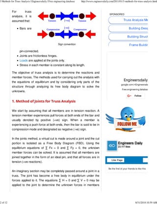
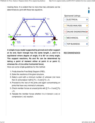
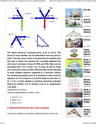
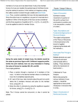
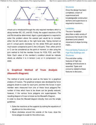
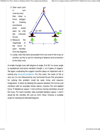
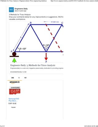
SlideShare a Scribd company logo
August 31, 2018 10:58:41 AM
Home » Civil Engineering » Mechanical Engineering » Mechanics »
Structural Analyses » structures » 3 Methods for Truss Analysis
3 Methods for Truss Analysis
Before discussing the
various methods of truss
analysis, it would be
appropriate to have a brief
introduction.
A structure that is composed
of a number of bars pin
connected at their ends to
form a stable framework is
called a truss. It is generally
assumed that loads and
reactions are applied to the truss only at the joints. A truss would
typically be composed of triangular elements with the bars on the
upper chord under compression and those along the lower chord
under tension. Trusses are extensively used for bridges, long span
roofs, electric tower, and space structures.
Trusses are statically determinate when the entire bar forces can
be determined from the equations of statics alone. Otherwise the
truss is statically indeterminate. A truss may be statically (externally)
determinate or indeterminate with respect to the reactions (more
than 3 or 6 reactions in 2D or 3D problems respectively).
SPONSORED
SENFENG® CO2 Laser Cutter
Used for
Drilling,Engraving,Carving
Cut for Non-Metal & Metal
Materials.
RESOURCES BOOKS MAGAZINES SPREADSHEETS BECOME A SPONSOR/ADVERTISER
Text to search...
3 Methods for Truss Analysis | Engineersdaily | Free engineering database http://www.engineersdaily.com/2011/01/3-methods-for-truss-analysis.html
1 of 12 8/31/2018 10:59 AM
Sign convention
For truss
analysis, it is
assumed that:
Bars are
pin-connected.
Joints are frictionless hinges.
Loads are applied at the joints only.
Stress in each member is constant along its length.
The objective of truss analysis is to determine the reactions and
member forces. The methods used for carrying out the analysis with
the equations of equilibrium and by considering only parts of the
structure through analyzing its free body diagram to solve the
unknowns.
1. Method of Joints for Truss Analysis
We start by assuming that all members are in tension reaction. A
tension member experiences pull forces at both ends of the bar and
usually denoted by positive (+ve) sign. When a member is
experiencing a push force at both ends, then the bar is said to be in
compression mode and designated as negative (-ve) sign.
In the joints method, a virtual cut is made around a joint and the cut
portion is isolated as a Free Body Diagram (FBD). Using the
equilibrium equations of ∑ Fx = 0 and ∑ Fy = 0, the unknown
member forces can be solved. It is assumed that all members are
joined together in the form of an ideal pin, and that all forces are in
tension (+ve reactions).
An imaginary section may be completely passed around a joint in a
truss. The joint has become a free body in equilibrium under the
forces applied to it. The equations ∑ H = 0 and ∑ V = 0 may be
applied to the joint to determine the unknown forces in members
SPONSORED
Be the first of your friends to like this
3 Methods for Truss Analysis | Engineersdaily | Free engineering database http://www.engineersdaily.com/2011/01/3-methods-for-truss-analysis.html
2 of 12 8/31/2018 10:59 AM
RECOMMENDED
meeting there. It is evident that no more than two unknowns can be
determined at a joint with these two equations.
A simple truss model supported by pinned and roller support
at its end. Each triangle has the same length, L and it is
equilateral where degree of angle, θ is 60° on every angle.
The support reactions, Ra and Rc can be determined by
taking a point of moment either at point A or point C,
whereas Ha = 0 (no other horizontal force).
Here are some simple guidelines for this method:
Firstly draw the Free Body Diagram (FBD),1.
Solve the reactions of the given structure,2.
Select a joint with a minimum number of unknown (not more
than 2) and analyze it with ∑ Fx = 0 and ∑ Fy = 0,
3.
Proceed to the rest of the joints and again concentrating on
joints that have very minimal of unknowns,
4.
Check member forces at unused joints with ∑ Fx = 0 and ∑ Fy
= 0,
5.
Tabulate the member forces whether it is in tension (+ve) or
compression (-ve) reaction.
6.
Subscribe via Email
Sponsored Listings
a
a
a
a
a
ELECTRICAL
TRUSS ANALYSIS
ONLINE ENGINEERING
MECHANICAL
TOP BUSINESS
1
2
3
4
5
3 Methods for Truss Analysis | Engineersdaily | Free engineering database http://www.engineersdaily.com/2011/01/3-methods-for-truss-analysis.html
3 of 12 8/31/2018 10:59 AM
The figure showing 3 selected joints, at B, C, and E. The
forces in each member can be determined from any joint or
point. The best way to start is by selecting the easiest joint
like joint C where the reaction Rc is already obtained and
with only 2 unknown, forces of FCB and FCD. Both can be
evaluated with ∑ Fx = 0 and ∑ Fy = 0 rules. At joint E, there
are 3 unknown, forces of FEA, FEB and FED, which may lead
to more complex solution compared to 2 unknown values.
For checking purposes, joint B is selected to show that the
equation of ∑ Fx is equal to ∑ Fy which leads to zero value, ∑
Fx = ∑ Fy = 0. Each member’s condition should be indicated
clearly as whether it is in tension (+ve) or in compression
(-ve) state.
Trigonometric Functions:
Taking an angle between member x and z…
Cos θ = x / z1.
Sin θ = y / z2.
Tan θ = y / x3.
2. Method of Sections for Truss Analysis
The section method is an effective method when the forces in all
Dry Mortar Mi
Ad NFLG
PCB Fab and
Assembly
Ad PCBA Store
Statically
Determinate T
engineersdaily.com
AcTouch Clou
Ad AcTouch Technolog
Types, Assum
and Fundame
Approaches o
engineersdaily.com
Book: Irrigati
Engineering a
Hydraulic...
engineersdaily.com
Types of Hydr
Dredgers
engineersdaily.com
Solved Examp
Method of Joi
Truss Analysis
engineersdaily.com
Book: Concre
Technology 2
Edition by A.
engineersdaily.com
Materials Use
Bridge Constr
engineersdaily.com
Analysis of 2D
Structure in S
2000
engineersdaily.com
3 Methods for Truss Analysis | Engineersdaily | Free engineering database http://www.engineersdaily.com/2011/01/3-methods-for-truss-analysis.html
4 of 12 8/31/2018 10:59 AM
Popular Categori
es
Follow us
members of a truss are to be determined. If only a few member
forces of a truss are needed, the quickest way to find these forces
is by the method of sections. In this method, an imaginary cutting
line called a section is drawn through a stable and determinate
truss. Thus, a section subdivides the truss into two separate parts.
Since the entire truss is in equilibrium, any part of it must also be in
equilibrium. Either of the two parts of the truss can be considered
and the three equations of equilibrium ∑ Fx = 0, ∑ Fy = 0, and ∑ M =
0 can be applied to solve for member forces.
Using the same model of simple truss, the details would be
the same as previous figure with 2 different supports profile.
Unlike the joint method, here we only interested in finding
the value of forces for member BC, EC, and ED.
Few simple guidelines:
Pass a section through a maximum of 3 members of the
truss, 1 of which is the desired member where it is dividing the
truss into 2 completely separate parts,
1.
At 1 part of the truss, take moments about the point (at a joint)
where the 2 members intersect and solve for the member
force, using ∑ M = 0,
2.
Solve the other 2 unknowns by using the equilibrium equation
for forces, using ∑ Fx = 0 and ∑ Fy = 0.
3.
Note: The 3 forces cannot be concurrent, or else it cannot be
solved.
Types of Excavation
Earthwork involves
movement of a portion of
the earth’s surface from
one location to another and,
in its new position, creation
of a desir...
Types, Assumptions and
Fundamental Approaches of
Structural Analysis
The subject and purposes
of the Theory of Structures
in the broad sense is the
branch of applied
engineering that deals with
the methods o...
How Loads Flow Through a
Building?
Multiple elements are used
to transmit and resist
external loads within a
building . These elements
define the mechanism of
load transfer i...
3 Methods for Truss
Analysis
Before discussing the
various methods of truss
analysis , it would be
appropriate to have a brief
introduction. A structure that
is comp...
Steps in Construction of
Reinforced Concrete
3 Methods for Truss Analysis | Engineersdaily | Free engineering database http://www.engineersdaily.com/2011/01/3-methods-for-truss-analysis.html
5 of 12 8/31/2018 10:59 AM
A
virtual cut is introduced through the only required members which is
along member BC, EC, and ED. Firstly, the support reactions of Ra
and Rd should be determined. Again a good judgment is required to
solve this problem where the easiest part would be to consider
either the left hand side or the right hand side. Taking moment at
joint E (virtual point) clockwise for the whole RHS part would be
much easier compared to joint C (the LHS part). Then, either joint D
or C can be considered as the point of moment, or else using the
joint method to find the member forces for FCB, FCE, and FDE.
Note: Each value of the member’s condition should be indicate
clearly as whether it is in tension (+ve) or in compression (-ve)
state.
3. Graphical Method of Truss Analysis
(Maxwell’s Diagram)
The method of joints could be used as the basis for a graphical
analysis of trusses. The graphical analysis was developed by force
polygons drawn to scale for each joint, and then the forces in each
member were measured from one of these force polygons.The
number of lines which have to be drawn can be greatly reduced,
however, if the various force polygons are superimposed. The
resulting diagram of truss is known as the Maxwell’s Diagram.
In order to draw the Maxwell diagram directly, here are the simple
guidelines:
Solve the reactions at the supports by solving the equations of
equilibrium for the entire truss,
1.
Move clockwise around the outside of the truss; draw the
force polygon to scale for the entire truss,
2.
Structures
Once the design has been
completed, a team of
experienced and
knowledgeable construction
workers and supervisors is
required to transform...
Landslides
The term "landslide"
describes a wide variety of
processes that result in the
downward and outward
movement of slope-forming
mater...
Fire and Safety Features of
High-Rise Buildings and
Structures
Fire and other safety
features of high rise
buildings and structures is
essential. Types and
concerns related to these
features is discusse...
3 Methods for Truss Analysis | Engineersdaily | Free engineering database http://www.engineersdaily.com/2011/01/3-methods-for-truss-analysis.html
6 of 12 8/31/2018 10:59 AM
Take each joint
in turn
(one-by-one),
then draw a
force polygon
by treating
successive
joints acted
upon by only
two unknown
forces,
3.
Measure the
magnitude of
the force in
each member
from the diagram,
4.
Lastly, note that work proceeded from one end of the truss to
another, as this is use for checking of balance and connection
to the other end.
5.
A simple triangle truss with degree of angle, θ is 60°on every angle
(a equilateral) and same member’s length, L on 2 types of support.
Yet again, evaluating the support reaction plays an important role in
solving any structural problems. For this case, the value of Hb is
zero as it is not influenced by any horizontal forces.The procedure
for solving this problem could be quite tricky and requires
imagination. It starts by labeling the spaces between the forces and
members with an example shown above; reaction Ra and applied
force, P labeled as space 1 and continue moving clockwise around
the truss. For each member, take example between space 1 and 5
would be the member AC and so forth. Note: Choose a suitable
scale for drawing the Maxwell diagram.
3 Methods for Truss Analysis | Engineersdaily | Free engineering database http://www.engineersdaily.com/2011/01/3-methods-for-truss-analysis.html
7 of 12 8/31/2018 10:59 AM
In conclusion, the truss internal reactions as well as its member
forces could be determined by either of these 3 methods.
Nonetheless, the methods of joints becomes the most preferred
method when it comes to more complex structures.
For more information on the topic:
☞Analysis of 2D Truss Structure in SAP 2000
☞Statically Determinate Trusses
☞Solved Examples for Method of Joints for Truss Analysis
☞Truss Analysis
Like and share this article on facebook:
3 Methods for Truss Analysis | Engineersdaily | Free engineering database http://www.engineersdaily.com/2011/01/3-methods-for-truss-analysis.html
8 of 12 8/31/2018 10:59 AM
EUR 18,92
Samsung EVO
Plus Micro...
Kaufen
Engineers Daily
about 2 years ago
3 Methods for Truss Analysis
Drop your comments below for any improvements or suggestions. We'll be happy to accommoda
valuable contributions.
268 5 101
3 Methods for Truss Analysis | Engineersdaily | Free engineering database http://www.engineersdaily.com/2011/01/3-methods-for-truss-analysis.html
9 of 12 8/31/2018 10:59 AM
Sponsored Listings
Online Engineering Programs
Top Business Colleges
Top Engineering Colleges
Engineering Jobs 2018
School Of Engineering
aa
aa
aa
aa
aa
Labels: Civil Engineering, Mechanical Engineering, Mechanics,
SPONSORED
7
Dry Mortar Mix Plant
Ad NFLG
Statically
Determinate Trusses
engineersdaily.com
PCB Fab and
Assembly
Ad PCBA Store
Smart Dredger.
Ad Aquamec Ltd.
Book: Irrigation
Engineering and
Hydraulic...
engineersdaily.com
Types of Hydraulic
Dredgers
engineersdaily.com
533
3 Methods for Truss Analysis | Engineersdaily | Free engineering database http://www.engineersdaily.com/2011/01/3-methods-for-truss-analysis.html
10 of 12 8/31/2018 10:59 AM
RELATED POSTS
Structural Analyses, structures
Next
Types of Hydraulic Dredgers
Previous
Landslides
Statically
Determinate
A truss is a
structure composed of slender
members that are connected at
their ends by joints. The ...Read
more »
27 Oct 2017 0
Solved Examples
for Method of
The theoretical
basis of the method of joints for
truss analysis has already been
discussed in this ...Read more »
27 Oct 2017 0
What is a Force
and How to
Force The concept
of force can be taken from our
daily experience. Although
forces cannot be seen ...Read
more »
29 Oct 2017 0
Materials Used for
Bridge
Materials Used in
Bridge Construction Stones,
Timber, Concrete and Steel are
the traditional mate...Read more
»
05 Feb 2018 0
Fire and Safety
Features of
Fire and other
safety features of high rise
buildings and structures is
essential. Types and
concer...Read more »
25 Aug 2018 0
3 Methods for Truss Analysis | Engineersdaily | Free engineering database http://www.engineersdaily.com/2011/01/3-methods-for-truss-analysis.html
11 of 12 8/31/2018 10:59 AM
Sponsored Listings
Your Online Survey
Start a Small Business
Cheap Laptop Deals
Totally Free Stuff
Today's Free Samples
a
a
a
a
a
Engineersdaily | Free engineering database © 2018 All Rights Reserved.
3 Methods for Truss Analysis | Engineersdaily | Free engineering database http://www.engineersdaily.com/2011/01/3-methods-for-truss-analysis.html
12 of 12 8/31/2018 10:59 AM

More Related Content

What's hot

Analysis of Truss
Analysis of TrussAnalysis of Truss
Analysis of Truss
Manvinder Kingra
 
Slope Deflection Method
Slope Deflection MethodSlope Deflection Method
Slope Deflection Method
Mahdi Damghani
 
Moment Distribution Method
Moment Distribution MethodMoment Distribution Method
Moment Distribution Method
Bhavik A Shah
 
Shear centre
Shear centreShear centre
Shear centre
Anirudh Ashok
 
Trusses - engineeing mechanics
Trusses - engineeing mechanicsTrusses - engineeing mechanics
Trusses - engineeing mechanics
JSPM'S BSIOTR
 
Moment Distribution Method SA-2
Moment Distribution Method SA-2Moment Distribution Method SA-2
Moment Distribution Method SA-2
Kaizer Dave
 
Tension members
Tension membersTension members
Tension members
sky hawk
 
Shear stresses in beams
Shear stresses in beamsShear stresses in beams
Shear stresses in beams
Shivendra Nandan
 
3.1 betti's law and maxwell's receprocal theorem
3.1 betti's law and maxwell's receprocal theorem3.1 betti's law and maxwell's receprocal theorem
3.1 betti's law and maxwell's receprocal theorem
Nilesh Baglekar
 
Two way slab
Two way slabTwo way slab
Two way slab
Priodeep Chowdhury
 
determinate and indeterminate structures
determinate and indeterminate structuresdeterminate and indeterminate structures
determinate and indeterminate structures
vempatishiva
 
Design of tension members
Design of tension membersDesign of tension members
Design of tension members
Sabna Thilakan
 
Direct integration method
Direct integration methodDirect integration method
Direct integration method
Mahdi Damghani
 
Trusses and its applications
Trusses and its applicationsTrusses and its applications
Trusses and its applications
Milan Joshi
 
CE- 416 Truss & Frame
CE- 416 Truss & FrameCE- 416 Truss & Frame
CE- 416 Truss & Frame
limon1705
 
Design of two-way slab
Design of two-way slabDesign of two-way slab
Design of two-way slab
civilengineeringfreedownload
 
_lateral_earth_pressure_(foundation engineering)
_lateral_earth_pressure_(foundation engineering)_lateral_earth_pressure_(foundation engineering)
_lateral_earth_pressure_(foundation engineering)
sharda university
 
Unsymmetrical bending.ppt
Unsymmetrical bending.pptUnsymmetrical bending.ppt
Unsymmetrical bending.ppt
Venkatesh Ca
 
STRENGTH OF MATERIALS for beginners
STRENGTH OF MATERIALS for  beginnersSTRENGTH OF MATERIALS for  beginners
STRENGTH OF MATERIALS for beginners
musadoto
 

What's hot (20)

Analysis of Truss
Analysis of TrussAnalysis of Truss
Analysis of Truss
 
Slope Deflection Method
Slope Deflection MethodSlope Deflection Method
Slope Deflection Method
 
Moment Distribution Method
Moment Distribution MethodMoment Distribution Method
Moment Distribution Method
 
1
11
1
 
Shear centre
Shear centreShear centre
Shear centre
 
Trusses - engineeing mechanics
Trusses - engineeing mechanicsTrusses - engineeing mechanics
Trusses - engineeing mechanics
 
Moment Distribution Method SA-2
Moment Distribution Method SA-2Moment Distribution Method SA-2
Moment Distribution Method SA-2
 
Tension members
Tension membersTension members
Tension members
 
Shear stresses in beams
Shear stresses in beamsShear stresses in beams
Shear stresses in beams
 
3.1 betti's law and maxwell's receprocal theorem
3.1 betti's law and maxwell's receprocal theorem3.1 betti's law and maxwell's receprocal theorem
3.1 betti's law and maxwell's receprocal theorem
 
Two way slab
Two way slabTwo way slab
Two way slab
 
determinate and indeterminate structures
determinate and indeterminate structuresdeterminate and indeterminate structures
determinate and indeterminate structures
 
Design of tension members
Design of tension membersDesign of tension members
Design of tension members
 
Direct integration method
Direct integration methodDirect integration method
Direct integration method
 
Trusses and its applications
Trusses and its applicationsTrusses and its applications
Trusses and its applications
 
CE- 416 Truss & Frame
CE- 416 Truss & FrameCE- 416 Truss & Frame
CE- 416 Truss & Frame
 
Design of two-way slab
Design of two-way slabDesign of two-way slab
Design of two-way slab
 
_lateral_earth_pressure_(foundation engineering)
_lateral_earth_pressure_(foundation engineering)_lateral_earth_pressure_(foundation engineering)
_lateral_earth_pressure_(foundation engineering)
 
Unsymmetrical bending.ppt
Unsymmetrical bending.pptUnsymmetrical bending.ppt
Unsymmetrical bending.ppt
 
STRENGTH OF MATERIALS for beginners
STRENGTH OF MATERIALS for  beginnersSTRENGTH OF MATERIALS for  beginners
STRENGTH OF MATERIALS for beginners
 

Similar to Truss analysis by graphical method

Introduction to the theory of plates
Introduction to the theory of platesIntroduction to the theory of plates
Introduction to the theory of plates
ABHISHEK CHANDA
 
Long span
Long spanLong span
Long span
Indrajit Koner
 
Structures and Materials- Section 1 Statics
Structures and Materials- Section 1 StaticsStructures and Materials- Section 1 Statics
Structures and Materials- Section 1 Statics
The Engineering Centre for Excellence in Teaching and Learning
 
TRUSS ANALYSIS (TERM PAPER REPORT)
TRUSS ANALYSIS (TERM PAPER REPORT)TRUSS ANALYSIS (TERM PAPER REPORT)
TRUSS ANALYSIS (TERM PAPER REPORT)
Sunil Kumar
 
Introduction fea
Introduction feaIntroduction fea
Introduction fea
ahmad saepuddin
 
Truss
TrussTruss
L04 5.pdf (trusses)
L04 5.pdf (trusses)L04 5.pdf (trusses)
L04 5.pdf (trusses)
nur izzaati
 
Truss.pptx
Truss.pptxTruss.pptx
Truss.pptx
prantaroy7
 
Truss & its analysis
Truss & its analysisTruss & its analysis
Truss & its analysis
Sunil Kumar
 
A Numerical Method For Friction Problems With Multiple Contacts
A Numerical Method For Friction Problems With Multiple ContactsA Numerical Method For Friction Problems With Multiple Contacts
A Numerical Method For Friction Problems With Multiple Contacts
Joshua Gorinson
 
LNm3.pdf
LNm3.pdfLNm3.pdf
LNm3.pdf
Dhanesh32
 
Lecture 3.pdf
Lecture 3.pdfLecture 3.pdf
Lecture 3.pdf
Yesuf3
 
Lecture2
Lecture2Lecture2
Lecture2
Gokul Nathan
 
Chapter4
Chapter4Chapter4
Chapter4
fatima7225
 
Engineering mechanics for diploma-Trusses.pptx
Engineering mechanics for diploma-Trusses.pptxEngineering mechanics for diploma-Trusses.pptx
Engineering mechanics for diploma-Trusses.pptx
RadhaKrishna860590
 

Similar to Truss analysis by graphical method (20)

Introduction to the theory of plates
Introduction to the theory of platesIntroduction to the theory of plates
Introduction to the theory of plates
 
Long span
Long spanLong span
Long span
 
Structures and Materials- Section 1 Statics
Structures and Materials- Section 1 StaticsStructures and Materials- Section 1 Statics
Structures and Materials- Section 1 Statics
 
TRUSS ANALYSIS (TERM PAPER REPORT)
TRUSS ANALYSIS (TERM PAPER REPORT)TRUSS ANALYSIS (TERM PAPER REPORT)
TRUSS ANALYSIS (TERM PAPER REPORT)
 
Introduction fea
Introduction feaIntroduction fea
Introduction fea
 
Truss
TrussTruss
Truss
 
Trusses.pdf
Trusses.pdfTrusses.pdf
Trusses.pdf
 
L04 5.pdf (trusses)
L04 5.pdf (trusses)L04 5.pdf (trusses)
L04 5.pdf (trusses)
 
Truss.pptx
Truss.pptxTruss.pptx
Truss.pptx
 
Truss & its analysis
Truss & its analysisTruss & its analysis
Truss & its analysis
 
A Numerical Method For Friction Problems With Multiple Contacts
A Numerical Method For Friction Problems With Multiple ContactsA Numerical Method For Friction Problems With Multiple Contacts
A Numerical Method For Friction Problems With Multiple Contacts
 
Trusses
TrussesTrusses
Trusses
 
Trusses
TrussesTrusses
Trusses
 
Trusses
TrussesTrusses
Trusses
 
LNm3.pdf
LNm3.pdfLNm3.pdf
LNm3.pdf
 
Lecture 3.pdf
Lecture 3.pdfLecture 3.pdf
Lecture 3.pdf
 
Lecture2
Lecture2Lecture2
Lecture2
 
Chapter4
Chapter4Chapter4
Chapter4
 
Engineering mechanics for diploma-Trusses.pptx
Engineering mechanics for diploma-Trusses.pptxEngineering mechanics for diploma-Trusses.pptx
Engineering mechanics for diploma-Trusses.pptx
 
Senior Project Report
Senior Project Report Senior Project Report
Senior Project Report
 

More from hitusp

CE6704_uw.pdf
CE6704_uw.pdfCE6704_uw.pdf
CE6704_uw.pdf
hitusp
 
GTE 1.pdf
GTE 1.pdfGTE 1.pdf
GTE 1.pdf
hitusp
 
EE.pdf
EE.pdfEE.pdf
EE.pdf
hitusp
 
Concrete mix deisgn
Concrete mix deisgnConcrete mix deisgn
Concrete mix deisgn
hitusp
 
New open document text
New open document textNew open document text
New open document texthitusp
 
New open document text
New open document textNew open document text
New open document texthitusp
 
Mech viva questions and_answers
Mech viva questions and_answersMech viva questions and_answers
Mech viva questions and_answershitusp
 
L01 03
L01 03L01 03
L01 03hitusp
 
Engineering mechanics-question-and-answers-for-gate-ias
Engineering mechanics-question-and-answers-for-gate-iasEngineering mechanics-question-and-answers-for-gate-ias
Engineering mechanics-question-and-answers-for-gate-iashitusp
 
Engineeringmechanics 140517073005-phpapp02
Engineeringmechanics 140517073005-phpapp02Engineeringmechanics 140517073005-phpapp02
Engineeringmechanics 140517073005-phpapp02hitusp
 
Engineering mechanics iii-lecture_notes_of_meen-321_kinematics_of_machinery_h...
Engineering mechanics iii-lecture_notes_of_meen-321_kinematics_of_machinery_h...Engineering mechanics iii-lecture_notes_of_meen-321_kinematics_of_machinery_h...
Engineering mechanics iii-lecture_notes_of_meen-321_kinematics_of_machinery_h...hitusp
 
Cse i-elements of civil engg. & engineering mechanics [10 civ-13]-notes
Cse i-elements of civil engg. &  engineering mechanics [10 civ-13]-notesCse i-elements of civil engg. &  engineering mechanics [10 civ-13]-notes
Cse i-elements of civil engg. & engineering mechanics [10 civ-13]-noteshitusp
 
Ch14the basics of_engineering_mechanics
Ch14the basics of_engineering_mechanicsCh14the basics of_engineering_mechanics
Ch14the basics of_engineering_mechanicshitusp
 

More from hitusp (15)

CE6704_uw.pdf
CE6704_uw.pdfCE6704_uw.pdf
CE6704_uw.pdf
 
GTE 1.pdf
GTE 1.pdfGTE 1.pdf
GTE 1.pdf
 
EE.pdf
EE.pdfEE.pdf
EE.pdf
 
Concrete mix deisgn
Concrete mix deisgnConcrete mix deisgn
Concrete mix deisgn
 
New open document text
New open document textNew open document text
New open document text
 
New open document text
New open document textNew open document text
New open document text
 
Mech viva questions and_answers
Mech viva questions and_answersMech viva questions and_answers
Mech viva questions and_answers
 
L01 03
L01 03L01 03
L01 03
 
Ks
KsKs
Ks
 
Gr
GrGr
Gr
 
Engineering mechanics-question-and-answers-for-gate-ias
Engineering mechanics-question-and-answers-for-gate-iasEngineering mechanics-question-and-answers-for-gate-ias
Engineering mechanics-question-and-answers-for-gate-ias
 
Engineeringmechanics 140517073005-phpapp02
Engineeringmechanics 140517073005-phpapp02Engineeringmechanics 140517073005-phpapp02
Engineeringmechanics 140517073005-phpapp02
 
Engineering mechanics iii-lecture_notes_of_meen-321_kinematics_of_machinery_h...
Engineering mechanics iii-lecture_notes_of_meen-321_kinematics_of_machinery_h...Engineering mechanics iii-lecture_notes_of_meen-321_kinematics_of_machinery_h...
Engineering mechanics iii-lecture_notes_of_meen-321_kinematics_of_machinery_h...
 
Cse i-elements of civil engg. & engineering mechanics [10 civ-13]-notes
Cse i-elements of civil engg. &  engineering mechanics [10 civ-13]-notesCse i-elements of civil engg. &  engineering mechanics [10 civ-13]-notes
Cse i-elements of civil engg. & engineering mechanics [10 civ-13]-notes
 
Ch14the basics of_engineering_mechanics
Ch14the basics of_engineering_mechanicsCh14the basics of_engineering_mechanics
Ch14the basics of_engineering_mechanics
 

Recently uploaded

Vaccine management system project report documentation..pdf
Vaccine management system project report documentation..pdfVaccine management system project report documentation..pdf
Vaccine management system project report documentation..pdf
Kamal Acharya
 
addressing modes in computer architecture
addressing modes  in computer architectureaddressing modes  in computer architecture
addressing modes in computer architecture
ShahidSultan24
 
CME397 Surface Engineering- Professional Elective
CME397 Surface Engineering- Professional ElectiveCME397 Surface Engineering- Professional Elective
CME397 Surface Engineering- Professional Elective
karthi keyan
 
J.Yang, ICLR 2024, MLILAB, KAIST AI.pdf
J.Yang,  ICLR 2024, MLILAB, KAIST AI.pdfJ.Yang,  ICLR 2024, MLILAB, KAIST AI.pdf
J.Yang, ICLR 2024, MLILAB, KAIST AI.pdf
MLILAB
 
CFD Simulation of By-pass Flow in a HRSG module by R&R Consult.pptx
CFD Simulation of By-pass Flow in a HRSG module by R&R Consult.pptxCFD Simulation of By-pass Flow in a HRSG module by R&R Consult.pptx
CFD Simulation of By-pass Flow in a HRSG module by R&R Consult.pptx
R&R Consult
 
ASME IX(9) 2007 Full Version .pdf
ASME IX(9)  2007 Full Version       .pdfASME IX(9)  2007 Full Version       .pdf
ASME IX(9) 2007 Full Version .pdf
AhmedHussein950959
 
Student information management system project report ii.pdf
Student information management system project report ii.pdfStudent information management system project report ii.pdf
Student information management system project report ii.pdf
Kamal Acharya
 
COLLEGE BUS MANAGEMENT SYSTEM PROJECT REPORT.pdf
COLLEGE BUS MANAGEMENT SYSTEM PROJECT REPORT.pdfCOLLEGE BUS MANAGEMENT SYSTEM PROJECT REPORT.pdf
COLLEGE BUS MANAGEMENT SYSTEM PROJECT REPORT.pdf
Kamal Acharya
 
LIGA(E)11111111111111111111111111111111111111111.ppt
LIGA(E)11111111111111111111111111111111111111111.pptLIGA(E)11111111111111111111111111111111111111111.ppt
LIGA(E)11111111111111111111111111111111111111111.ppt
ssuser9bd3ba
 
Pile Foundation by Venkatesh Taduvai (Sub Geotechnical Engineering II)-conver...
Pile Foundation by Venkatesh Taduvai (Sub Geotechnical Engineering II)-conver...Pile Foundation by Venkatesh Taduvai (Sub Geotechnical Engineering II)-conver...
Pile Foundation by Venkatesh Taduvai (Sub Geotechnical Engineering II)-conver...
AJAYKUMARPUND1
 
block diagram and signal flow graph representation
block diagram and signal flow graph representationblock diagram and signal flow graph representation
block diagram and signal flow graph representation
Divya Somashekar
 
Hybrid optimization of pumped hydro system and solar- Engr. Abdul-Azeez.pdf
Hybrid optimization of pumped hydro system and solar- Engr. Abdul-Azeez.pdfHybrid optimization of pumped hydro system and solar- Engr. Abdul-Azeez.pdf
Hybrid optimization of pumped hydro system and solar- Engr. Abdul-Azeez.pdf
fxintegritypublishin
 
Nuclear Power Economics and Structuring 2024
Nuclear Power Economics and Structuring 2024Nuclear Power Economics and Structuring 2024
Nuclear Power Economics and Structuring 2024
Massimo Talia
 
NO1 Uk best vashikaran specialist in delhi vashikaran baba near me online vas...
NO1 Uk best vashikaran specialist in delhi vashikaran baba near me online vas...NO1 Uk best vashikaran specialist in delhi vashikaran baba near me online vas...
NO1 Uk best vashikaran specialist in delhi vashikaran baba near me online vas...
Amil Baba Dawood bangali
 
Automobile Management System Project Report.pdf
Automobile Management System Project Report.pdfAutomobile Management System Project Report.pdf
Automobile Management System Project Report.pdf
Kamal Acharya
 
Standard Reomte Control Interface - Neometrix
Standard Reomte Control Interface - NeometrixStandard Reomte Control Interface - Neometrix
Standard Reomte Control Interface - Neometrix
Neometrix_Engineering_Pvt_Ltd
 
Quality defects in TMT Bars, Possible causes and Potential Solutions.
Quality defects in TMT Bars, Possible causes and Potential Solutions.Quality defects in TMT Bars, Possible causes and Potential Solutions.
Quality defects in TMT Bars, Possible causes and Potential Solutions.
PrashantGoswami42
 
Forklift Classes Overview by Intella Parts
Forklift Classes Overview by Intella PartsForklift Classes Overview by Intella Parts
Forklift Classes Overview by Intella Parts
Intella Parts
 
Water Industry Process Automation and Control Monthly - May 2024.pdf
Water Industry Process Automation and Control Monthly - May 2024.pdfWater Industry Process Automation and Control Monthly - May 2024.pdf
Water Industry Process Automation and Control Monthly - May 2024.pdf
Water Industry Process Automation & Control
 
MCQ Soil mechanics questions (Soil shear strength).pdf
MCQ Soil mechanics questions (Soil shear strength).pdfMCQ Soil mechanics questions (Soil shear strength).pdf
MCQ Soil mechanics questions (Soil shear strength).pdf
Osamah Alsalih
 

Recently uploaded (20)

Vaccine management system project report documentation..pdf
Vaccine management system project report documentation..pdfVaccine management system project report documentation..pdf
Vaccine management system project report documentation..pdf
 
addressing modes in computer architecture
addressing modes  in computer architectureaddressing modes  in computer architecture
addressing modes in computer architecture
 
CME397 Surface Engineering- Professional Elective
CME397 Surface Engineering- Professional ElectiveCME397 Surface Engineering- Professional Elective
CME397 Surface Engineering- Professional Elective
 
J.Yang, ICLR 2024, MLILAB, KAIST AI.pdf
J.Yang,  ICLR 2024, MLILAB, KAIST AI.pdfJ.Yang,  ICLR 2024, MLILAB, KAIST AI.pdf
J.Yang, ICLR 2024, MLILAB, KAIST AI.pdf
 
CFD Simulation of By-pass Flow in a HRSG module by R&R Consult.pptx
CFD Simulation of By-pass Flow in a HRSG module by R&R Consult.pptxCFD Simulation of By-pass Flow in a HRSG module by R&R Consult.pptx
CFD Simulation of By-pass Flow in a HRSG module by R&R Consult.pptx
 
ASME IX(9) 2007 Full Version .pdf
ASME IX(9)  2007 Full Version       .pdfASME IX(9)  2007 Full Version       .pdf
ASME IX(9) 2007 Full Version .pdf
 
Student information management system project report ii.pdf
Student information management system project report ii.pdfStudent information management system project report ii.pdf
Student information management system project report ii.pdf
 
COLLEGE BUS MANAGEMENT SYSTEM PROJECT REPORT.pdf
COLLEGE BUS MANAGEMENT SYSTEM PROJECT REPORT.pdfCOLLEGE BUS MANAGEMENT SYSTEM PROJECT REPORT.pdf
COLLEGE BUS MANAGEMENT SYSTEM PROJECT REPORT.pdf
 
LIGA(E)11111111111111111111111111111111111111111.ppt
LIGA(E)11111111111111111111111111111111111111111.pptLIGA(E)11111111111111111111111111111111111111111.ppt
LIGA(E)11111111111111111111111111111111111111111.ppt
 
Pile Foundation by Venkatesh Taduvai (Sub Geotechnical Engineering II)-conver...
Pile Foundation by Venkatesh Taduvai (Sub Geotechnical Engineering II)-conver...Pile Foundation by Venkatesh Taduvai (Sub Geotechnical Engineering II)-conver...
Pile Foundation by Venkatesh Taduvai (Sub Geotechnical Engineering II)-conver...
 
block diagram and signal flow graph representation
block diagram and signal flow graph representationblock diagram and signal flow graph representation
block diagram and signal flow graph representation
 
Hybrid optimization of pumped hydro system and solar- Engr. Abdul-Azeez.pdf
Hybrid optimization of pumped hydro system and solar- Engr. Abdul-Azeez.pdfHybrid optimization of pumped hydro system and solar- Engr. Abdul-Azeez.pdf
Hybrid optimization of pumped hydro system and solar- Engr. Abdul-Azeez.pdf
 
Nuclear Power Economics and Structuring 2024
Nuclear Power Economics and Structuring 2024Nuclear Power Economics and Structuring 2024
Nuclear Power Economics and Structuring 2024
 
NO1 Uk best vashikaran specialist in delhi vashikaran baba near me online vas...
NO1 Uk best vashikaran specialist in delhi vashikaran baba near me online vas...NO1 Uk best vashikaran specialist in delhi vashikaran baba near me online vas...
NO1 Uk best vashikaran specialist in delhi vashikaran baba near me online vas...
 
Automobile Management System Project Report.pdf
Automobile Management System Project Report.pdfAutomobile Management System Project Report.pdf
Automobile Management System Project Report.pdf
 
Standard Reomte Control Interface - Neometrix
Standard Reomte Control Interface - NeometrixStandard Reomte Control Interface - Neometrix
Standard Reomte Control Interface - Neometrix
 
Quality defects in TMT Bars, Possible causes and Potential Solutions.
Quality defects in TMT Bars, Possible causes and Potential Solutions.Quality defects in TMT Bars, Possible causes and Potential Solutions.
Quality defects in TMT Bars, Possible causes and Potential Solutions.
 
Forklift Classes Overview by Intella Parts
Forklift Classes Overview by Intella PartsForklift Classes Overview by Intella Parts
Forklift Classes Overview by Intella Parts
 
Water Industry Process Automation and Control Monthly - May 2024.pdf
Water Industry Process Automation and Control Monthly - May 2024.pdfWater Industry Process Automation and Control Monthly - May 2024.pdf
Water Industry Process Automation and Control Monthly - May 2024.pdf
 
MCQ Soil mechanics questions (Soil shear strength).pdf
MCQ Soil mechanics questions (Soil shear strength).pdfMCQ Soil mechanics questions (Soil shear strength).pdf
MCQ Soil mechanics questions (Soil shear strength).pdf
 

Truss analysis by graphical method

  • 1. August 31, 2018 10:58:41 AM Home » Civil Engineering » Mechanical Engineering » Mechanics » Structural Analyses » structures » 3 Methods for Truss Analysis 3 Methods for Truss Analysis Before discussing the various methods of truss analysis, it would be appropriate to have a brief introduction. A structure that is composed of a number of bars pin connected at their ends to form a stable framework is called a truss. It is generally assumed that loads and reactions are applied to the truss only at the joints. A truss would typically be composed of triangular elements with the bars on the upper chord under compression and those along the lower chord under tension. Trusses are extensively used for bridges, long span roofs, electric tower, and space structures. Trusses are statically determinate when the entire bar forces can be determined from the equations of statics alone. Otherwise the truss is statically indeterminate. A truss may be statically (externally) determinate or indeterminate with respect to the reactions (more than 3 or 6 reactions in 2D or 3D problems respectively). SPONSORED SENFENG® CO2 Laser Cutter Used for Drilling,Engraving,Carving Cut for Non-Metal & Metal Materials. RESOURCES BOOKS MAGAZINES SPREADSHEETS BECOME A SPONSOR/ADVERTISER Text to search... 3 Methods for Truss Analysis | Engineersdaily | Free engineering database http://www.engineersdaily.com/2011/01/3-methods-for-truss-analysis.html 1 of 12 8/31/2018 10:59 AM
  • 2. Sign convention For truss analysis, it is assumed that: Bars are pin-connected. Joints are frictionless hinges. Loads are applied at the joints only. Stress in each member is constant along its length. The objective of truss analysis is to determine the reactions and member forces. The methods used for carrying out the analysis with the equations of equilibrium and by considering only parts of the structure through analyzing its free body diagram to solve the unknowns. 1. Method of Joints for Truss Analysis We start by assuming that all members are in tension reaction. A tension member experiences pull forces at both ends of the bar and usually denoted by positive (+ve) sign. When a member is experiencing a push force at both ends, then the bar is said to be in compression mode and designated as negative (-ve) sign. In the joints method, a virtual cut is made around a joint and the cut portion is isolated as a Free Body Diagram (FBD). Using the equilibrium equations of ∑ Fx = 0 and ∑ Fy = 0, the unknown member forces can be solved. It is assumed that all members are joined together in the form of an ideal pin, and that all forces are in tension (+ve reactions). An imaginary section may be completely passed around a joint in a truss. The joint has become a free body in equilibrium under the forces applied to it. The equations ∑ H = 0 and ∑ V = 0 may be applied to the joint to determine the unknown forces in members SPONSORED Be the first of your friends to like this 3 Methods for Truss Analysis | Engineersdaily | Free engineering database http://www.engineersdaily.com/2011/01/3-methods-for-truss-analysis.html 2 of 12 8/31/2018 10:59 AM
  • 3. RECOMMENDED meeting there. It is evident that no more than two unknowns can be determined at a joint with these two equations. A simple truss model supported by pinned and roller support at its end. Each triangle has the same length, L and it is equilateral where degree of angle, θ is 60° on every angle. The support reactions, Ra and Rc can be determined by taking a point of moment either at point A or point C, whereas Ha = 0 (no other horizontal force). Here are some simple guidelines for this method: Firstly draw the Free Body Diagram (FBD),1. Solve the reactions of the given structure,2. Select a joint with a minimum number of unknown (not more than 2) and analyze it with ∑ Fx = 0 and ∑ Fy = 0, 3. Proceed to the rest of the joints and again concentrating on joints that have very minimal of unknowns, 4. Check member forces at unused joints with ∑ Fx = 0 and ∑ Fy = 0, 5. Tabulate the member forces whether it is in tension (+ve) or compression (-ve) reaction. 6. Subscribe via Email Sponsored Listings a a a a a ELECTRICAL TRUSS ANALYSIS ONLINE ENGINEERING MECHANICAL TOP BUSINESS 1 2 3 4 5 3 Methods for Truss Analysis | Engineersdaily | Free engineering database http://www.engineersdaily.com/2011/01/3-methods-for-truss-analysis.html 3 of 12 8/31/2018 10:59 AM
  • 4. The figure showing 3 selected joints, at B, C, and E. The forces in each member can be determined from any joint or point. The best way to start is by selecting the easiest joint like joint C where the reaction Rc is already obtained and with only 2 unknown, forces of FCB and FCD. Both can be evaluated with ∑ Fx = 0 and ∑ Fy = 0 rules. At joint E, there are 3 unknown, forces of FEA, FEB and FED, which may lead to more complex solution compared to 2 unknown values. For checking purposes, joint B is selected to show that the equation of ∑ Fx is equal to ∑ Fy which leads to zero value, ∑ Fx = ∑ Fy = 0. Each member’s condition should be indicated clearly as whether it is in tension (+ve) or in compression (-ve) state. Trigonometric Functions: Taking an angle between member x and z… Cos θ = x / z1. Sin θ = y / z2. Tan θ = y / x3. 2. Method of Sections for Truss Analysis The section method is an effective method when the forces in all Dry Mortar Mi Ad NFLG PCB Fab and Assembly Ad PCBA Store Statically Determinate T engineersdaily.com AcTouch Clou Ad AcTouch Technolog Types, Assum and Fundame Approaches o engineersdaily.com Book: Irrigati Engineering a Hydraulic... engineersdaily.com Types of Hydr Dredgers engineersdaily.com Solved Examp Method of Joi Truss Analysis engineersdaily.com Book: Concre Technology 2 Edition by A. engineersdaily.com Materials Use Bridge Constr engineersdaily.com Analysis of 2D Structure in S 2000 engineersdaily.com 3 Methods for Truss Analysis | Engineersdaily | Free engineering database http://www.engineersdaily.com/2011/01/3-methods-for-truss-analysis.html 4 of 12 8/31/2018 10:59 AM
  • 5. Popular Categori es Follow us members of a truss are to be determined. If only a few member forces of a truss are needed, the quickest way to find these forces is by the method of sections. In this method, an imaginary cutting line called a section is drawn through a stable and determinate truss. Thus, a section subdivides the truss into two separate parts. Since the entire truss is in equilibrium, any part of it must also be in equilibrium. Either of the two parts of the truss can be considered and the three equations of equilibrium ∑ Fx = 0, ∑ Fy = 0, and ∑ M = 0 can be applied to solve for member forces. Using the same model of simple truss, the details would be the same as previous figure with 2 different supports profile. Unlike the joint method, here we only interested in finding the value of forces for member BC, EC, and ED. Few simple guidelines: Pass a section through a maximum of 3 members of the truss, 1 of which is the desired member where it is dividing the truss into 2 completely separate parts, 1. At 1 part of the truss, take moments about the point (at a joint) where the 2 members intersect and solve for the member force, using ∑ M = 0, 2. Solve the other 2 unknowns by using the equilibrium equation for forces, using ∑ Fx = 0 and ∑ Fy = 0. 3. Note: The 3 forces cannot be concurrent, or else it cannot be solved. Types of Excavation Earthwork involves movement of a portion of the earth’s surface from one location to another and, in its new position, creation of a desir... Types, Assumptions and Fundamental Approaches of Structural Analysis The subject and purposes of the Theory of Structures in the broad sense is the branch of applied engineering that deals with the methods o... How Loads Flow Through a Building? Multiple elements are used to transmit and resist external loads within a building . These elements define the mechanism of load transfer i... 3 Methods for Truss Analysis Before discussing the various methods of truss analysis , it would be appropriate to have a brief introduction. A structure that is comp... Steps in Construction of Reinforced Concrete 3 Methods for Truss Analysis | Engineersdaily | Free engineering database http://www.engineersdaily.com/2011/01/3-methods-for-truss-analysis.html 5 of 12 8/31/2018 10:59 AM
  • 6. A virtual cut is introduced through the only required members which is along member BC, EC, and ED. Firstly, the support reactions of Ra and Rd should be determined. Again a good judgment is required to solve this problem where the easiest part would be to consider either the left hand side or the right hand side. Taking moment at joint E (virtual point) clockwise for the whole RHS part would be much easier compared to joint C (the LHS part). Then, either joint D or C can be considered as the point of moment, or else using the joint method to find the member forces for FCB, FCE, and FDE. Note: Each value of the member’s condition should be indicate clearly as whether it is in tension (+ve) or in compression (-ve) state. 3. Graphical Method of Truss Analysis (Maxwell’s Diagram) The method of joints could be used as the basis for a graphical analysis of trusses. The graphical analysis was developed by force polygons drawn to scale for each joint, and then the forces in each member were measured from one of these force polygons.The number of lines which have to be drawn can be greatly reduced, however, if the various force polygons are superimposed. The resulting diagram of truss is known as the Maxwell’s Diagram. In order to draw the Maxwell diagram directly, here are the simple guidelines: Solve the reactions at the supports by solving the equations of equilibrium for the entire truss, 1. Move clockwise around the outside of the truss; draw the force polygon to scale for the entire truss, 2. Structures Once the design has been completed, a team of experienced and knowledgeable construction workers and supervisors is required to transform... Landslides The term "landslide" describes a wide variety of processes that result in the downward and outward movement of slope-forming mater... Fire and Safety Features of High-Rise Buildings and Structures Fire and other safety features of high rise buildings and structures is essential. Types and concerns related to these features is discusse... 3 Methods for Truss Analysis | Engineersdaily | Free engineering database http://www.engineersdaily.com/2011/01/3-methods-for-truss-analysis.html 6 of 12 8/31/2018 10:59 AM
  • 7. Take each joint in turn (one-by-one), then draw a force polygon by treating successive joints acted upon by only two unknown forces, 3. Measure the magnitude of the force in each member from the diagram, 4. Lastly, note that work proceeded from one end of the truss to another, as this is use for checking of balance and connection to the other end. 5. A simple triangle truss with degree of angle, θ is 60°on every angle (a equilateral) and same member’s length, L on 2 types of support. Yet again, evaluating the support reaction plays an important role in solving any structural problems. For this case, the value of Hb is zero as it is not influenced by any horizontal forces.The procedure for solving this problem could be quite tricky and requires imagination. It starts by labeling the spaces between the forces and members with an example shown above; reaction Ra and applied force, P labeled as space 1 and continue moving clockwise around the truss. For each member, take example between space 1 and 5 would be the member AC and so forth. Note: Choose a suitable scale for drawing the Maxwell diagram. 3 Methods for Truss Analysis | Engineersdaily | Free engineering database http://www.engineersdaily.com/2011/01/3-methods-for-truss-analysis.html 7 of 12 8/31/2018 10:59 AM
  • 8. In conclusion, the truss internal reactions as well as its member forces could be determined by either of these 3 methods. Nonetheless, the methods of joints becomes the most preferred method when it comes to more complex structures. For more information on the topic: ☞Analysis of 2D Truss Structure in SAP 2000 ☞Statically Determinate Trusses ☞Solved Examples for Method of Joints for Truss Analysis ☞Truss Analysis Like and share this article on facebook: 3 Methods for Truss Analysis | Engineersdaily | Free engineering database http://www.engineersdaily.com/2011/01/3-methods-for-truss-analysis.html 8 of 12 8/31/2018 10:59 AM
  • 9. EUR 18,92 Samsung EVO Plus Micro... Kaufen Engineers Daily about 2 years ago 3 Methods for Truss Analysis Drop your comments below for any improvements or suggestions. We'll be happy to accommoda valuable contributions. 268 5 101 3 Methods for Truss Analysis | Engineersdaily | Free engineering database http://www.engineersdaily.com/2011/01/3-methods-for-truss-analysis.html 9 of 12 8/31/2018 10:59 AM
  • 10. Sponsored Listings Online Engineering Programs Top Business Colleges Top Engineering Colleges Engineering Jobs 2018 School Of Engineering aa aa aa aa aa Labels: Civil Engineering, Mechanical Engineering, Mechanics, SPONSORED 7 Dry Mortar Mix Plant Ad NFLG Statically Determinate Trusses engineersdaily.com PCB Fab and Assembly Ad PCBA Store Smart Dredger. Ad Aquamec Ltd. Book: Irrigation Engineering and Hydraulic... engineersdaily.com Types of Hydraulic Dredgers engineersdaily.com 533 3 Methods for Truss Analysis | Engineersdaily | Free engineering database http://www.engineersdaily.com/2011/01/3-methods-for-truss-analysis.html 10 of 12 8/31/2018 10:59 AM
  • 11. RELATED POSTS Structural Analyses, structures Next Types of Hydraulic Dredgers Previous Landslides Statically Determinate A truss is a structure composed of slender members that are connected at their ends by joints. The ...Read more » 27 Oct 2017 0 Solved Examples for Method of The theoretical basis of the method of joints for truss analysis has already been discussed in this ...Read more » 27 Oct 2017 0 What is a Force and How to Force The concept of force can be taken from our daily experience. Although forces cannot be seen ...Read more » 29 Oct 2017 0 Materials Used for Bridge Materials Used in Bridge Construction Stones, Timber, Concrete and Steel are the traditional mate...Read more » 05 Feb 2018 0 Fire and Safety Features of Fire and other safety features of high rise buildings and structures is essential. Types and concer...Read more » 25 Aug 2018 0 3 Methods for Truss Analysis | Engineersdaily | Free engineering database http://www.engineersdaily.com/2011/01/3-methods-for-truss-analysis.html 11 of 12 8/31/2018 10:59 AM
  • 12. Sponsored Listings Your Online Survey Start a Small Business Cheap Laptop Deals Totally Free Stuff Today's Free Samples a a a a a Engineersdaily | Free engineering database © 2018 All Rights Reserved. 3 Methods for Truss Analysis | Engineersdaily | Free engineering database http://www.engineersdaily.com/2011/01/3-methods-for-truss-analysis.html 12 of 12 8/31/2018 10:59 AM