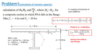
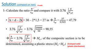
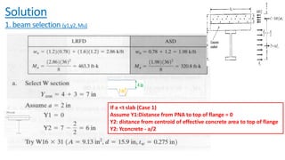
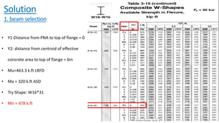
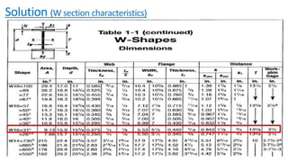
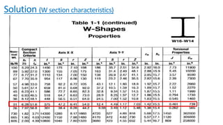
COMPOSITE CONSTRUCTION:
COMPOSITE BEAM SOLVED PROBLEMS
1
Presented By
Eng. ZEINAB AWADA
Email
Zeinabawada198@gmail.com
MASTER OF CIVIL ENGINEERING-LEBANON
ADVANCED STRUCTURAL SYSTEMS COURSE
Problem1(calculation of moment capacity)
K
E= modulus of elasticity of
steel 29000 Ksi
If Case 2: a > t slab then
Distance from PNA to
top of flange
Solution (compact or non) H web
(Compact web)
(plastic distribution)
Solution (position PNA)
Case 1: a < t slab so PNA in slab
Case 2: a > t slab so PNA in steel beam
If C>T PNA in steel flange
If C<T PNA in steel beam web
Solution
Distance from PNA to top of flange
Solution
• Beams 10 ft on center with 36 ft simple spans are to be selected to support a 4-in deep
lightweight concrete slab on a 3-in-deep formed steel deck with no shoring.
• The ribs for the steel deck, which are perpendicular to the beam center lines have average
widths of 6 in.
• The service dead load(including the beam weight) is 0,78 k/ft of length of the beams and the
service live load is 1.2 k/ft.
Fy=50Ksi, f’c=3Ksi
Problem 2 (beam design)
Solution
1. beam selection (y1,y2,Mu)
If a <t slab (Case 1)
Assume Y1:Distance from PNA to top of flange = 0
Y2: distance from centroid of effective concrete area to top of flange
Y2: Yconcrete - a/2
• Y1:Distance from PNA to top of flange = 0
• Y2: distance from centroid of effective
concrete area to top of flange = 6in
• Mu=463.3 k.ft LRFD
• Ma = 320 k.ft ASD
• Try Shape: W16*31
• Mn = 478 k.ft
Solution
1. beam selection
• Y1:Distance from PNA to top of flange = 0
• Y2: distance from centroid of effective
concrete area to top of flange = 6in
• Mu=463.3 k.ft LRFD
• Ma = 320 k.ft ASD
• Try Shape: W16*31
• Mn = 478 k.ft
Solution
1. beam selection
Solution (W section characteristics)
Solution
2.Check Mu <øMn
Ʃ 𝑄n = As.Fy
Or
Table
a < t slab then Y1= 0
Solution
3.Design of shear connectors
Given:
• Light weight concrete
• Fc’ = 3ksi
• Ribs of steel deck are perpendicular
to the beam center
• Stud diameter = ¾ in2
Solution
4. Check strength of W section before concrete hardens: øMn>Mu
= γ * t * tributary length
Beams 10 ft on center with 36 ft simple spans.
The ribs average widths of 6 in.
DEAD LOADS:
1. Deck weight (2psf)
2. Beam weight(31lb/ft)
LIVE LOADS
1. Slab weight
2. Rib weight
3. Construction live load(20psf)
W16*31
Solution
5.Check for service load deflection before concrete hardens
(Service load)
Solution
5.Check for service LL deflection after
composite section is available
∆L= ML.L2/C1*ILB
Given (Service live load) = 1.2k/ft
Solution
6.Check shear
DL = 0,78 k/ft
LL = 1.2 k/ft
Problem 3
Solution
Solution
Solution
THANK YOU
24
THANK YOU
Hope you enjoyed my presentation !
Contact me for any help
zeinabawada198@gmail.com
✓ Structural steel design,5th edition, jack C.Mc Cromac,S tephan F. Csernak
✓ American institude of steel construction, Steel construction manual, 14th edition
✓ Chapter 9
❖ References
25

composite beam problems.pdf

  • 1.
    COMPOSITE CONSTRUCTION: COMPOSITE BEAMSOLVED PROBLEMS 1 Presented By Eng. ZEINAB AWADA Email Zeinabawada198@gmail.com MASTER OF CIVIL ENGINEERING-LEBANON ADVANCED STRUCTURAL SYSTEMS COURSE
  • 2.
    Problem1(calculation of momentcapacity) K E= modulus of elasticity of steel 29000 Ksi If Case 2: a > t slab then Distance from PNA to top of flange
  • 3.
    Solution (compact ornon) H web (Compact web) (plastic distribution)
  • 4.
    Solution (position PNA) Case1: a < t slab so PNA in slab Case 2: a > t slab so PNA in steel beam If C>T PNA in steel flange If C<T PNA in steel beam web
  • 5.
  • 6.
  • 7.
    • Beams 10ft on center with 36 ft simple spans are to be selected to support a 4-in deep lightweight concrete slab on a 3-in-deep formed steel deck with no shoring. • The ribs for the steel deck, which are perpendicular to the beam center lines have average widths of 6 in. • The service dead load(including the beam weight) is 0,78 k/ft of length of the beams and the service live load is 1.2 k/ft. Fy=50Ksi, f’c=3Ksi Problem 2 (beam design)
  • 8.
    Solution 1. beam selection(y1,y2,Mu) If a <t slab (Case 1) Assume Y1:Distance from PNA to top of flange = 0 Y2: distance from centroid of effective concrete area to top of flange Y2: Yconcrete - a/2
  • 9.
    • Y1:Distance fromPNA to top of flange = 0 • Y2: distance from centroid of effective concrete area to top of flange = 6in • Mu=463.3 k.ft LRFD • Ma = 320 k.ft ASD • Try Shape: W16*31 • Mn = 478 k.ft Solution 1. beam selection
  • 10.
    • Y1:Distance fromPNA to top of flange = 0 • Y2: distance from centroid of effective concrete area to top of flange = 6in • Mu=463.3 k.ft LRFD • Ma = 320 k.ft ASD • Try Shape: W16*31 • Mn = 478 k.ft Solution 1. beam selection
  • 11.
    Solution (W sectioncharacteristics)
  • 12.
    Solution (W sectioncharacteristics)
  • 13.
    Solution 2.Check Mu <øMn Ʃ𝑄n = As.Fy Or Table a < t slab then Y1= 0
  • 14.
    Solution 3.Design of shearconnectors Given: • Light weight concrete • Fc’ = 3ksi • Ribs of steel deck are perpendicular to the beam center • Stud diameter = ¾ in2
  • 15.
    Solution 4. Check strengthof W section before concrete hardens: øMn>Mu = γ * t * tributary length Beams 10 ft on center with 36 ft simple spans. The ribs average widths of 6 in. DEAD LOADS: 1. Deck weight (2psf) 2. Beam weight(31lb/ft) LIVE LOADS 1. Slab weight 2. Rib weight 3. Construction live load(20psf) W16*31
  • 16.
    Solution 5.Check for serviceload deflection before concrete hardens (Service load)
  • 17.
    Solution 5.Check for serviceLL deflection after composite section is available ∆L= ML.L2/C1*ILB Given (Service live load) = 1.2k/ft
  • 18.
    Solution 6.Check shear DL =0,78 k/ft LL = 1.2 k/ft
  • 19.
  • 20.
  • 22.
  • 23.
  • 24.
    THANK YOU 24 THANK YOU Hopeyou enjoyed my presentation ! Contact me for any help zeinabawada198@gmail.com
  • 25.
    ✓ Structural steeldesign,5th edition, jack C.Mc Cromac,S tephan F. Csernak ✓ American institude of steel construction, Steel construction manual, 14th edition ✓ Chapter 9 ❖ References 25