1. The document describes the design of a simple shear connection between a beam and column using bolts. It provides equations to check the shear strength of the bolts and bearing strength of the plate.
2. An example is presented to determine the number and size of bolts needed to resist an ultimate shear force of 1000 kN between two beams. It is determined that 7 bolts with 18 mm diameter and 98.5 mm spacing will suffice.
3. The document also checks the strength of double angles used in the connection to transfer the force and confirms the chosen angles are adequate.
Design of Various Types of Industrial Buildings and Their ComparisonIRJESJOURNAL
ABSTRACT :- In this paper Industrial Steel truss Building of 14m x 31.50m, 20m x 50m, 28m x 70m and bay spacing of 5.25m, 6.25m and 7m respectively having column height of 6m is compared with Pre-engineering Buildings of same dimension. Design is based on IS 800-2007 (LSM) Load considered in modeling are Dead load, Live Load, Wind load along with the combinations as specified in IS. Analysis results are observed for column base as hinge base. Results of Industrial steel truss buildings are compared with the same dimensions of Pre-Engineering Building
Gantry girder
Gantry girder or crane girder hand operated or electrically operated overhead cranes in industrial building such as factories, workshops, steel works, etc. to lift heavy materials, equipment etc. and carry them from one location to other , within the building
The GANTRY GIRDER spans between brackets attached to columns, which may either be of steel or reinforced concrete. Thus the span of gantry girder is equal to centre to centre spacing of columns. The rails are mounted on gantry girders.
Loads acting on gantry girder
Gantry girder, having no lateral support in its length (laterally unsupported) has to withstand the following loads:
1. Vertical loads from crane :
Self weight of crane girder
Hook load
Weight of crab (trolley)
2. Impact load from crane :
As the load is lifted using the crane hook and moved from one place to another, and released at the required place, an impact is felt on the gantry girder.
3. Longitudinal horizontal force (Drag force) :
This is caused due to the starting and stopping of the crane girder moving over the crane rails, as the crane girder moves longitudinally, i.e. in the direction of gantry girder.
This force is also known as braking force, or drag force.
This force is taken equal to 5% of the static wheel loads for EOT or hand operated cranes.
4. Lateral load (Surge load) :
Lateral forces are caused due to sudden starting or stopping of the crab when moving over the crane girder.
Lateral forces are also caused when the crane is dragging weights across the' floor of the shop.
Types of gantry girders
Depending upon the span and crane capacity, there can be many forms of gantry girders. Some commonly used forms are shows in fig .
Rolled steel beams with or without plates, channels or angles are normally used for spans up to 8m and for cranes up to 50kN capacity.
Plate girder are suitable up to span 6 to 10 m.
Plate girder with channels, angles, etc. can be used for spans more than 10m
Box girder are used foe spans more than 12m.
Priliminary design of column
before going to give properties to the structure in the staad pro preliminary design have to be done to find out the dimensions of column
check it out: http://goo.gl/vqNk7m
CADmantra Technologies pvt. Ltd. is a CAD Training institute specilized in producing quality and high standard education and training. We are providing a perfact institute for the students intersted in CAD courses CADmantra is established by a group of engineers to devlop good training system in the field of CAD/CAM/CAE, these courses are widely accepted worldwide.
#catiatraining
#ANSYS #CRE-O
#hypermesh
#Automobileworkshops
#enginedevelopment
#autocad
#sketching
this slide will clear all the topics and problem related to singly reinforced beam by limit state method, things are explained with diagrams , easy to understand .
About
Indigenized remote control interface card suitable for MAFI system CCR equipment. Compatible for IDM8000 CCR. Backplane mounted serial and TCP/Ethernet communication module for CCR remote access. IDM 8000 CCR remote control on serial and TCP protocol.
• Remote control: Parallel or serial interface.
• Compatible with MAFI CCR system.
• Compatible with IDM8000 CCR.
• Compatible with Backplane mount serial communication.
• Compatible with commercial and Defence aviation CCR system.
• Remote control system for accessing CCR and allied system over serial or TCP.
• Indigenized local Support/presence in India.
• Easy in configuration using DIP switches.
Technical Specifications
Indigenized remote control interface card suitable for MAFI system CCR equipment. Compatible for IDM8000 CCR. Backplane mounted serial and TCP/Ethernet communication module for CCR remote access. IDM 8000 CCR remote control on serial and TCP protocol.
Key Features
Indigenized remote control interface card suitable for MAFI system CCR equipment. Compatible for IDM8000 CCR. Backplane mounted serial and TCP/Ethernet communication module for CCR remote access. IDM 8000 CCR remote control on serial and TCP protocol.
• Remote control: Parallel or serial interface
• Compatible with MAFI CCR system
• Copatiable with IDM8000 CCR
• Compatible with Backplane mount serial communication.
• Compatible with commercial and Defence aviation CCR system.
• Remote control system for accessing CCR and allied system over serial or TCP.
• Indigenized local Support/presence in India.
Application
• Remote control: Parallel or serial interface.
• Compatible with MAFI CCR system.
• Compatible with IDM8000 CCR.
• Compatible with Backplane mount serial communication.
• Compatible with commercial and Defence aviation CCR system.
• Remote control system for accessing CCR and allied system over serial or TCP.
• Indigenized local Support/presence in India.
• Easy in configuration using DIP switches.
Water scarcity is the lack of fresh water resources to meet the standard water demand. There are two type of water scarcity. One is physical. The other is economic water scarcity.
Forklift Classes Overview by Intella PartsIntella Parts
Discover the different forklift classes and their specific applications. Learn how to choose the right forklift for your needs to ensure safety, efficiency, and compliance in your operations.
For more technical information, visit our website https://intellaparts.com
Cosmetic shop management system project report.pdfKamal Acharya
Buying new cosmetic products is difficult. It can even be scary for those who have sensitive skin and are prone to skin trouble. The information needed to alleviate this problem is on the back of each product, but it's thought to interpret those ingredient lists unless you have a background in chemistry.
Instead of buying and hoping for the best, we can use data science to help us predict which products may be good fits for us. It includes various function programs to do the above mentioned tasks.
Data file handling has been effectively used in the program.
The automated cosmetic shop management system should deal with the automation of general workflow and administration process of the shop. The main processes of the system focus on customer's request where the system is able to search the most appropriate products and deliver it to the customers. It should help the employees to quickly identify the list of cosmetic product that have reached the minimum quantity and also keep a track of expired date for each cosmetic product. It should help the employees to find the rack number in which the product is placed.It is also Faster and more efficient way.
Saudi Arabia stands as a titan in the global energy landscape, renowned for its abundant oil and gas resources. It's the largest exporter of petroleum and holds some of the world's most significant reserves. Let's delve into the top 10 oil and gas projects shaping Saudi Arabia's energy future in 2024.
Final project report on grocery store management system..pdfKamal Acharya
In today’s fast-changing business environment, it’s extremely important to be able to respond to client needs in the most effective and timely manner. If your customers wish to see your business online and have instant access to your products or services.
Online Grocery Store is an e-commerce website, which retails various grocery products. This project allows viewing various products available enables registered users to purchase desired products instantly using Paytm, UPI payment processor (Instant Pay) and also can place order by using Cash on Delivery (Pay Later) option. This project provides an easy access to Administrators and Managers to view orders placed using Pay Later and Instant Pay options.
In order to develop an e-commerce website, a number of Technologies must be studied and understood. These include multi-tiered architecture, server and client-side scripting techniques, implementation technologies, programming language (such as PHP, HTML, CSS, JavaScript) and MySQL relational databases. This is a project with the objective to develop a basic website where a consumer is provided with a shopping cart website and also to know about the technologies used to develop such a website.
This document will discuss each of the underlying technologies to create and implement an e- commerce website.
Student information management system project report ii.pdfKamal Acharya
Our project explains about the student management. This project mainly explains the various actions related to student details. This project shows some ease in adding, editing and deleting the student details. It also provides a less time consuming process for viewing, adding, editing and deleting the marks of the students.
Welcome to WIPAC Monthly the magazine brought to you by the LinkedIn Group Water Industry Process Automation & Control.
In this month's edition, along with this month's industry news to celebrate the 13 years since the group was created we have articles including
A case study of the used of Advanced Process Control at the Wastewater Treatment works at Lleida in Spain
A look back on an article on smart wastewater networks in order to see how the industry has measured up in the interim around the adoption of Digital Transformation in the Water Industry.
CFD Simulation of By-pass Flow in a HRSG module by R&R Consult.pptxR&R Consult
CFD analysis is incredibly effective at solving mysteries and improving the performance of complex systems!
Here's a great example: At a large natural gas-fired power plant, where they use waste heat to generate steam and energy, they were puzzled that their boiler wasn't producing as much steam as expected.
R&R and Tetra Engineering Group Inc. were asked to solve the issue with reduced steam production.
An inspection had shown that a significant amount of hot flue gas was bypassing the boiler tubes, where the heat was supposed to be transferred.
R&R Consult conducted a CFD analysis, which revealed that 6.3% of the flue gas was bypassing the boiler tubes without transferring heat. The analysis also showed that the flue gas was instead being directed along the sides of the boiler and between the modules that were supposed to capture the heat. This was the cause of the reduced performance.
Based on our results, Tetra Engineering installed covering plates to reduce the bypass flow. This improved the boiler's performance and increased electricity production.
It is always satisfying when we can help solve complex challenges like this. Do your systems also need a check-up or optimization? Give us a call!
Work done in cooperation with James Malloy and David Moelling from Tetra Engineering.
More examples of our work https://www.r-r-consult.dk/en/cases-en/
CFD Simulation of By-pass Flow in a HRSG module by R&R Consult.pptx
21-Design of Simple Shear Connections (Steel Structural Design & Prof. Shehab Mourad)
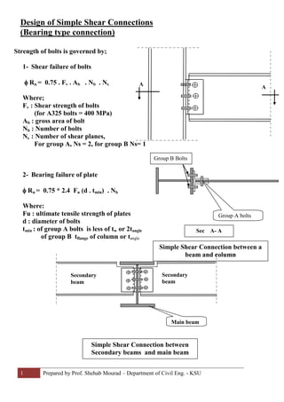
1. 1 Prepared by Prof. Shehab Mourad – Department of Civil Eng. - KSU
Design of Simple Shear Connections
(Bearing type connection)
Strength of bolts is governed by;
1- Shear failure of bolts
φ Rn = 0.75 . Fv . Ab . Nb . Ns
Where;
Fv : Shear strength of bolts
(for A325 bolts = 400 MPa)
Ab : gross area of bolt
Nb : Number of bolts
Ns : Number of shear planes,
For group A, Ns = 2, for group B Ns= 1
2- Bearing failure of plate
φ Rn = 0.75 * 2.4 Fu (d . tmin) . Nb
Where:
Fu : ultimate tensile strength of plates
d : diameter of bolts
tmin : of group A bolts is less of tw or 2tangle
of group B tflange of column or tangle
Group A bolts
Group B Bolts
Sec A- A
A
A
Simple Shear Connection between a
beam and column
Secondary
beam
Secondary
beam
Main beam
Simple Shear Connection between
Secondary beams and main beam
2. 2 Prepared by Prof. Shehab Mourad – Department of Civil Eng. - KSU
Example
Solution:
Check the shear strength at critical section
For W 480 x 473, h/tw = 756 / 26.4 = 28.6 < 2.45 2 x 105
= 69
250
∴ φVn = 0.9 x 0.6 Fy . Aw where Aw = (690 + 48 ) x 26.4 = 19483 mm2
φVn = 0.9 x 0.6 x 250 x 19483 x 10-3
= 2630 > Vu = 1000 kN ∴ OK
Strength of Bolts
a) Group (A) bolts (Double Shear)
1- Shear Failure, φ Rn = 0.75 x (πd2
/4) x 400 x Nb x 2 = Vu = 1000 x 103
∴ d2
Nb = 2122.07
Try , if
Nb d (mm) Spacing = 690/Nb
3 26.5 230mm = 8.67 d > 6d not OK
4 23 172 mm = 7.5 d > 6d not OK
5 20.6 138 mm = 6.7 d > 6d not OK
6 18.8 115 mm =6.1 d > 6d not OK
7 17.4 98.5mm = 5.6 d < 6d O.K
Determine the number of bolts
needed to support an ultimate
shear force = 1000 kN,
transformed from beam
W 840 x 473 to a main beam
W 920 x 653 with double
angles 65 x 65 with a length of
690 mm
F v for bolts = 400 MPa
Fu for steel = 400 MPa
Fy for steel = 250 MPa
For W 840 x 473
d= 893 mm
h = 756 mm
tw = 26.4 mm
tf = 48 mm
For W 920 x 653
d = 972 mm
tw = 34.5 mm
W 840 x 473
W 920 x 653
893 mm690 mm
155 mm
48 mm
Critical section
for shear
Group A bolts
Group B bolts
3. 3 Prepared by Prof. Shehab Mourad – Department of Civil Eng. - KSU
2- Check bearing strength for 7 M18 bolts
φ Rn = 0.75 x 2.4 Fu x d x tmin x Nb
= 0.75 x 2.4 x 400 x 18 x t min x 7 = 1000 x 103
∴ t min = 11.02 = 2 t angle
∴ tmin of angle = 5.5 mm
∴ Choose double angles 65 x 65 x 6.35 mm
b) Group (B) bolts (Single Shear)
1- Check Shear Failure,
φ Rn = 0.75 x (π 18 2
/4) x 400 x 14 x 1 x 10-3
= 1068.8 kN > Vu = 1000 kN
2- Check bearing strength
φ Rn = = 0.75 x 2.4 x 400 x 18 x 6.35 x 14 x 10-3
= 1152 kN > 1000 kN
Check shear block of double angles
D hole = 18 + 3 = 21 mm
Lv = 6.5 s = 6.5 x 98.5 = 640.25 mm
Av= 640.25 x 2 x 6.35 = 8131.2 mm2
Avn = 8131.2 – (6.5 x 21 x 6.35 x 2) = 6397.65 mm2
Gage distance g = 35 mm , Lt = 65 - 35 = 30 mm
Atg = 30 x 6.35 x 2 = 381 mm2
Atn = 381 – 0.5 x 21 x 6.35 x 2 = 247.65 mm2
0.6 Fu Avn = 0.6 x 400 x 6397.65 x 10-3
= 1535.44 kN
Fu Atn = 400 x 247.65 = 99.06 kN
0.6 Fu Avn > Fu Atn
φ Rn = 0.75 [0.6 Fu Avn + Fy Atg]
φ Rn = 0.75 [ 1535.4 + 250 x 381 x 10-3
] = 1223 kN > Vu = 1000 kN
∴ Choose 7 bolts with
diameter 18 mm with
spacing = 98.5 mm for
group A
∴ Use 14 M18 for group B bolts
∴ double angles 65 x 65 x 6.35 mm with 7 M 18 A325 bolts with spacing 98.5 mm
and gage distance g = 35 mm are sufficient to resist Vu = 1000 kN
s/2
690 mm
s
s
s
s
s
s
s/2
s = 98.5 mm
g
s/2
s
s
s
s
s
s
s/2
g Lt
Lv