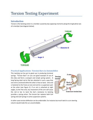
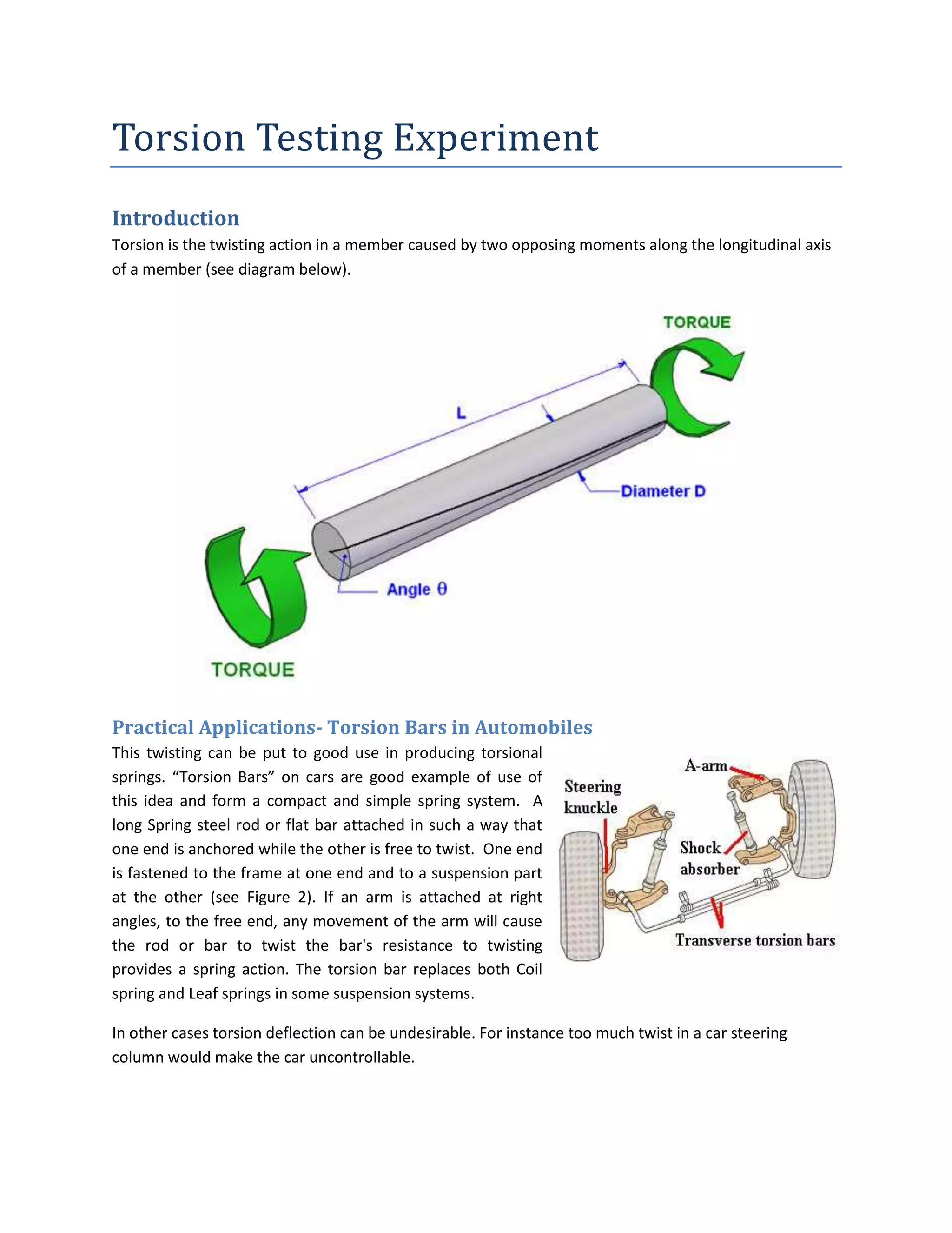
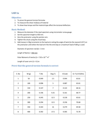
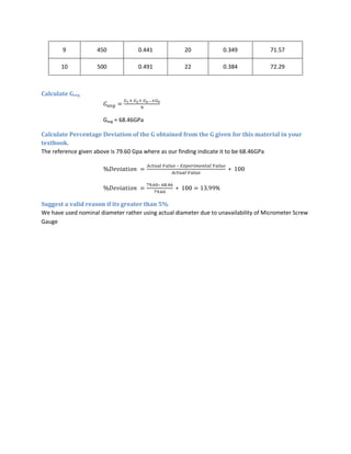
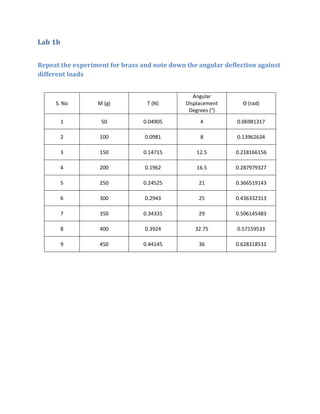
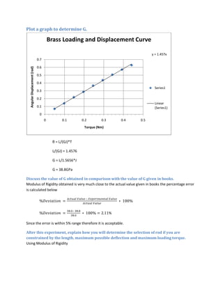
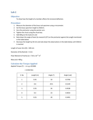
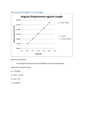
The document describes a torsion testing experiment. The objectives are to:
1. Determine the shear modulus (G) of different materials and the relationship between applied torque and angular twist.
2. Examine how material length affects angular twist.
The experiment involves twisting steel and brass rods of different lengths using known torques and measuring the angular deflection. Graphs of the data are used to calculate G, finding values of 68.46 GPa for steel and 38.8 GPa for brass, which are close to reference values. Testing another brass rod of varying lengths, a graph shows angular twist increases proportionally with length. G is recalculated from this graph as 43.50 GPa
1. Torsion Testing Experiment
Introduction
Torsion is the twisting action in a member caused by two opposing moments along the longitudinal axis
of a member (see diagram below).
Practical Applications- Torsion Bars in Automobiles
This twisting can be put to good use in producing torsional
springs. “Torsion Bars” on cars are good example of use of
this idea and form a compact and simple spring system. A
long Spring steel rod or flat bar attached in such a way that
one end is anchored while the other is free to twist. One end
is fastened to the frame at one end and to a suspension part
at the other (see Figure 2). If an arm is attached at right
angles, to the free end, any movement of the arm will cause
the rod or bar to twist the bar's resistance to twisting
provides a spring action. The torsion bar replaces both Coil
spring and Leaf springs in some suspension systems.
In other cases torsion deflection can be undesirable. For instance too much twist in a car steering
column would make the car uncontrollable.
2. Give any other application of studying torsion?
_____________________________________________________________________________________
_____________________________________________________________________________________
_____________________________________________________________________________________
3. The Torsion Test
The Torsion Test allows the student to investigate the relationships between the moment (torque)
applied to a member, the material, member length and torsional deflection. Theoretically it can be
proved that:
Where:
G = Shear Modulus (pa)
T = Applied Torque or moment (Nm)
J = Polar Moment of Inertia (m)
θ = Angle of twist (rads)
L = Effective length of member (m)
Lab Objectives
This Lab consists of two experiments. The objectives of each experiment is discussed below
1. To twist two different materials to find shear modulus “G”, and the relationship between the
applied moment and the angle of twist
2. To twist a material to see how the length affects the angle of twist.
Assumptions
In our experiments we take the following assumptions:
1. Material is homogenous
2. Circular section remains circular and do not deform.
3. A plane section of a material perpendicular to it's longitudinal axis remain plane and do not
deform after the torque is applied.
4. Shaft is loaded by a couple or torque in a plane perpendicular to the longitudinal axis of the
plane.
5. the torsion of the drill chucks or the cone shaped mandrels is negligible compared to the torsion
of the test bars.
6. There is negligible friction between the supporting rod and the chuck.
7. Shear stress is proportional to shear strain, it means Hook's Law is applicable.
8. In circular shafts subjected to torque shearing strain varies linearly.
Where τ, Shearing stress in MPa,
r = Radius of shaft in mm
T = Twisting Moment
J = Polar moment of inertia.
4. G = Modulus of rigidity.
θ = Angle of Twist
L = Length of the specimen
Safety Warning:
Ensure that the chucks are as tight as possible to avoid slipping.
The Equipment
The device allows the fundamental relationships of elastic deformation associated with torsion to be
measured and investigated. It is called torsion tester. In this experiment a load is applied to different
test bars and the resulting deformation measured..
The equipment consists of a loading arm with a protractor the is allowed to pivot freely and torsionally
fixed end, which can be moved up and down to give various effective lengths. Drill type chucks at each
end grip the specimen.
Accessories Provided
1. Measuring Tape
2. 2 Specimen Rods (Steel, Brass)
3. Micrometer Screw Guage
4. Weight Hanger
5. Total 50 weights of 10g each
6. Chuck key
5. Reference Material
Some Additional Information:
Shear Moduli:
Steel = 79.6 GPa
Brass = 38.0 GPa
Nominal specimen diameter = 3 mm
for a circular cross section
Where:
D = Diameter of a section
6. Demo for students
The stresses caused by the torsional forces in a material are complicated. Firstly, there are shear stresses
along the axis member and secondly, there are compressive and tensile stresses at 45° to the axis. We’ll
not calculate it but simply demonstrate to proof that they exist.
Procedure for Shear Stress
1. You are given two pieces of pipe one is solid where as the second have a slit along its length
2. Grip and twist both pieces and compare.
What do you observe?
theslatted piece will twist easily and show the shear forces created
Procedure for Compressive and Tensile Stresses
1. You are given a piece of ordinary circular section board chalk.
2. Twist it gently until it breaks.
What angle does it breaks?
The chalks breaks roughly 45 degrees to the axis (forming a helix) indicating the maximum stress plane
(in tension for chalk)
7. LAB 1a
Objective:
1. To prove the general torsion formulae
2. To measure the shear modulus of material
3. To show how torque and the material type affect the torsional deflection.
Basic Method:
1. Measure the diameter if the steel specimen using micrometer screw gauge.
2. Set the specimen length to 450 mm.
3. Zero the protractor using the pointer arm.
4. Tighten the chuck using the chuck keys.
5. Add masses in 50g increments to the load arm noting the angle of twist (to the nearest 0.25°) on
the protractor until either the load arm hits the end stop or a maximum load of 500 g is used.
Diameter of specimen rod (d) = 3 mm
Length of Rod (L) = 450 mm
Polar Moment of Inertia (J) = 7.95 x 10⁻¹² m4
Length of Lever arm (r) = 0.1m
Prove that the general torsion formula is correct
S. No M (g) T (N) Deg (°) Θ (rad) G= TL/J θ (GPa)
1 50 0.049 2.5 0.044 63.61
2 100 0.098 5 0.087 63.61
3 150 0.147 7 0.122 68.16
4 200 0.196 9.25 0.161 68.77
5 250 0.245 12.5 0.218 63.61
6 300 0.294 13.5 0.236 70.68
7 350 0.343 16 0.279 69.58
8 400 0.392 17.5 0.305 72.70
8. 9 450 0.441 20 0.349 71.57
10 500 0.491 22 0.384 72.29
Calculate Gavg
Gavg = 68.46GPa
Calculate Percentage Deviation of the G obtained from the G given for this material in your
textbook.
The reference given above is 79.60 Gpa where as our finding indicate it to be 68.46GPa
–
–
%
Suggest a valid reason if its greater than 5%
We have used nominal diameter rather using actual diameter due to unavailability of Micrometer Screw
Gauge
9. Lab 1b
Repeat the experiment for brass and note down the angular deflection against
different loads
Angular
S. No M (g) T (N) Displacement Θ (rad)
Degrees (°)
1 50 0.04905 4 0.06981317
2 100 0.0981 8 0.13962634
3 150 0.14715 12.5 0.218166156
4 200 0.1962 16.5 0.287979327
5 250 0.24525 21 0.366519143
6 300 0.2943 25 0.436332313
7 350 0.34335 29 0.506145483
8 400 0.3924 32.75 0.57159533
9 450 0.44145 36 0.628318531
10. Plot a graph to determine G.
Brass Loading and Displacement Curve
y = 1.457x
0.7
0.6
Angular Displacement (rad)
0.5
0.4
Series1
0.3
0.2
Linear
0.1 (Series1)
0
0 0.1 0.2 0.3 0.4 0.5
Torque (Nm)
θ = L/(GJ)*T
L/(GJ) = 1.4576
G = L/1.5656*J
G = 38.8GPa
Discuss the value of G obtained in comparison with the value of G given in books.
Modulus of Rigidity obtained is very much close to the actual value given in books the percentage error
is calculated below
–
–
%
Since the error is within 5% range therefore it is acceptable.
After this experiment, explain how you will determine the selection of rod if you are
constrained by the length, maximum possible deflection and maximum loading torque.
Using Modulus of Rigidity
11. Lab 2
Objective
To show how the length of a member affects the torsional deflection.
Procedure
1. Measure the diameter of the brass rod specimen using a micrometer.
2. Set the brass specimen length to 450mm.
3. Zero the protractor using the pointer arm.
4. Tighten the chuck using the chuck key.
5. Add 400 g to the load arm and
6. Note down the angle of twist (to nearest 0.25°) on the protractor against the Length mentioned
in the table below
7. Decrease the length by 50 mm and note down the observations in the table below until 250mm
is reached
Length of Lever Arm (R) = 100 mm
Diameter of the Rod (d) = 3 mm
Polar Moment of Inertia (J) = 7.95 x 10⁻¹² m4
Mass (m)= 400 g
Calculate the Torque Applied
Applied Torque (T) = m x g x R/1000
= 0.3924 Nm
S. No Length (m) Angle (°) Angle (rad)
1 0.45 33 0.5760
2 0.4 29.5 0.5149
3 0.35 26 0.4538
4 0.3 23 0.4014
5 0.25 20 0.3491
12. Plot a graph of Angle versus Length.
Angular Displacement against Length
0.6000
y = 1.134x + 0.062
0.5500
Angular Displacement (rad)
0.5000
0.4500
Series1
0.4000 Linear (Series1)
0.3500
0.3000
0.2 0.25 0.3 0.35 0.4 0.45 0.5
Length (m)
What do you observe?
As the length increases the angle of deflection increasesproportionally
Determine G using the Graph
Θ = L*(T/(GJ))
m = T/GJ = 1.1345
G = 1/m * T/J
G = 43.50 GPa